EP0484615A1 - Manually operated pump device for dispensing fluids - Google Patents
Manually operated pump device for dispensing fluids Download PDFInfo
- Publication number
- EP0484615A1 EP0484615A1 EP91105907A EP91105907A EP0484615A1 EP 0484615 A1 EP0484615 A1 EP 0484615A1 EP 91105907 A EP91105907 A EP 91105907A EP 91105907 A EP91105907 A EP 91105907A EP 0484615 A1 EP0484615 A1 EP 0484615A1
- Authority
- EP
- European Patent Office
- Prior art keywords
- pump device
- gasket
- stem
- cylinder
- delivery
- Prior art date
- Legal status (The legal status is an assumption and is not a legal conclusion. Google has not performed a legal analysis and makes no representation as to the accuracy of the status listed.)
- Granted
Links
Images

Classifications
-
- B—PERFORMING OPERATIONS; TRANSPORTING
- B05—SPRAYING OR ATOMISING IN GENERAL; APPLYING FLUENT MATERIALS TO SURFACES, IN GENERAL
- B05B—SPRAYING APPARATUS; ATOMISING APPARATUS; NOZZLES
- B05B11/00—Single-unit hand-held apparatus in which flow of contents is produced by the muscular force of the operator at the moment of use
- B05B11/01—Single-unit hand-held apparatus in which flow of contents is produced by the muscular force of the operator at the moment of use characterised by the means producing the flow
- B05B11/10—Pump arrangements for transferring the contents from the container to a pump chamber by a sucking effect and forcing the contents out through the dispensing nozzle
- B05B11/1001—Piston pumps
- B05B11/1004—Piston pumps comprising a movable cylinder and a stationary piston
-
- B—PERFORMING OPERATIONS; TRANSPORTING
- B05—SPRAYING OR ATOMISING IN GENERAL; APPLYING FLUENT MATERIALS TO SURFACES, IN GENERAL
- B05B—SPRAYING APPARATUS; ATOMISING APPARATUS; NOZZLES
- B05B11/00—Single-unit hand-held apparatus in which flow of contents is produced by the muscular force of the operator at the moment of use
- B05B11/01—Single-unit hand-held apparatus in which flow of contents is produced by the muscular force of the operator at the moment of use characterised by the means producing the flow
- B05B11/10—Pump arrangements for transferring the contents from the container to a pump chamber by a sucking effect and forcing the contents out through the dispensing nozzle
- B05B11/1001—Piston pumps
- B05B11/1009—Piston pumps actuated by a lever
- B05B11/1011—Piston pumps actuated by a lever without substantial movement of the nozzle in the direction of the pressure stroke
-
- B—PERFORMING OPERATIONS; TRANSPORTING
- B05—SPRAYING OR ATOMISING IN GENERAL; APPLYING FLUENT MATERIALS TO SURFACES, IN GENERAL
- B05B—SPRAYING APPARATUS; ATOMISING APPARATUS; NOZZLES
- B05B11/00—Single-unit hand-held apparatus in which flow of contents is produced by the muscular force of the operator at the moment of use
- B05B11/01—Single-unit hand-held apparatus in which flow of contents is produced by the muscular force of the operator at the moment of use characterised by the means producing the flow
- B05B11/10—Pump arrangements for transferring the contents from the container to a pump chamber by a sucking effect and forcing the contents out through the dispensing nozzle
- B05B11/1095—Pump arrangements for transferring the contents from the container to a pump chamber by a sucking effect and forcing the contents out through the dispensing nozzle with movable suction side
-
- B—PERFORMING OPERATIONS; TRANSPORTING
- B05—SPRAYING OR ATOMISING IN GENERAL; APPLYING FLUENT MATERIALS TO SURFACES, IN GENERAL
- B05B—SPRAYING APPARATUS; ATOMISING APPARATUS; NOZZLES
- B05B11/00—Single-unit hand-held apparatus in which flow of contents is produced by the muscular force of the operator at the moment of use
- B05B11/01—Single-unit hand-held apparatus in which flow of contents is produced by the muscular force of the operator at the moment of use characterised by the means producing the flow
- B05B11/10—Pump arrangements for transferring the contents from the container to a pump chamber by a sucking effect and forcing the contents out through the dispensing nozzle
- B05B11/1097—Pump arrangements for transferring the contents from the container to a pump chamber by a sucking effect and forcing the contents out through the dispensing nozzle with means for sucking back the liquid or other fluent material in the nozzle after a dispensing stroke
Definitions
- This invention relates to a manually operated pump device for dispensing fluids from containers, particularly of the portable type for connection to said containers, for example by threaded ring nuts or capsules.
- Fluid dispensing pumps consisting substantially of a trigger lever, a delivery channel and a handgrip containing in its interior a pumping system formed from a cylinder-piston assembly operationally connected to the lever, suction and delivery valves, and elastic return means.
- the unidirectional valves provided in known pumps consist of shutoff valves of conventional type, for example of gravity or spring-loaded type.
- the object of the invention is to provide a reliable manually operated pump device for dispensing fluids, which does not give rise to the aforesaid drawbacks, and in particular which can be used inclined at any angle to its axis or even inverted, and can also dispense highly viscous or gluey fluids, while being composed of only a small number of relatively simple components which can be obtained by moulding plastics material, and are easily assembled.
- the pump according to the invention is characterised by comprising a mobile cylinder operationally connected to an operating trigger lever, a suction valve comprising a stem-like member and a valve seat at one end of said cylinder, said stem-like member being axially mobile within the cylinder and passing through an elastically deformable stationary gasket which during the delivery stage separates from the stem-like member to thus allow passage of the fluid, whereas during the suction stage it adheres to said member to provide a seal.
- the pump device shown in Figure 1 comprises a body A with a hollow cylindrical handgrip 1.
- the lower part of the handgrip 1 is connected to a screw cap 3 for connecting the device to the container containing the fluid to be delivered.
- the upper part is provided with a preferably diverging delivery channel 4 and two parallel spaced-apart shoulders 5 acting as lateral guides for a trigger lever 2.
- the delivery channel 4 terminates with a delivery head 6 which is rotatable to allow adjustment of the shape of the emitted flow, as described hereinafter.
- the trigger lever 2 is pivoted on the supports 7 provided on the inner walls of the shoulders 5, and can move from the rest position 2 in which one end of the lever is in contact with the delivery channel, to the maximum operation position 2'.
- the trigger lever 2 also comprises two arms 32 which pass through a suitable aperture provided in the cylindrical wall of the handgrip 1 to cooperate with a collar 8 of a mobile cylinder 9 Provided within said handgrip 1.
- the cylinder 9 slides along the walls of a fixed piston 10 and contracts lowerly into bottle-neck shape with a frusto-conical part 13 which when the trigger lever 2 is not operated rests on the lower collar of a ring 11.
- the end 12' of the neck engages with a dip-tube 12 which dips into the fluid to be dispensed.
- the outer wall of the cylinder 9 comprises an axial cavity 20 extending for a short distance prior to the bottle-neck.
- the ring 11 is shaped at one end in such a manner as to form a usual snap-fit with the handgrip 1, which is shaped correspondingly thereat.
- the handgrip and ring 11 On the vertical line through the cavity 20 in the cylinder 9, the handgrip and ring 11 comprise a channel 21 connected to the outside.
- the ring 11 comprises a collar 15 which together with the terminal part of the handgrip 1 forms an annular recess in which the screw cap 3 engages.
- a stem-like member 14 Within the mobile cylinder 9 and piston 10, in a chamber defined by these latter, there are provided a stem-like member 14, a gasket 16 and a loading or return spring 17.
- the stem-like member 14 is arranged axially to the cylinder and has its bottom end 23 of frusto-conical shape with its base diameter greater than the rest of the member 14 and its inclination equal to the inclination of the frusto-conical part 13 of the mobile cylinder 9.
- Said stem-like member 14 also comprises a rib 19, and ribs 25 which extend for a certain distance from the base of the conical portion 23.
- Said stem-like member also passes through the gasket 16 to cooperate with ribs 24 which act as a guide and are positioned radially in the inner wall of the fixed piston 10 above said gasket 16.
- the gasket 16 is substantially of frusto-conical cap shape comprising a lower diverging toroidal band 16A in contact with the lateral walls of the mobile cylinder 9, a central step 16B externally in contact with the lower end of the fixed piston 10 and internally in contact with the end of the spring 17, and a conical terminal lip 34 which is thinner than the other portions and has its end in contact with the stem-like member 14.
- the toroidal band and the lip provide the seal against the cylinder 9 and against the stem-like member 14 respectively, during the operation of the pump.
- the spring 17 is retained upperly in the inner stepped part of the gasket 16 and lowerly in suitable ribs 18 provided within the conical part of the cylinder 9, but without acting directly on the conical portion 23 of the stem-like member 14.
- the delivery head 6 is snap-fitted to an annular portion 26 at the end of the variable-section delivery channel 4, and according to its position it either connects said channel 4, via a groove 32 and a fixed channel 40 in said annular portion 26, to one of the different-shaped orifices 31, 30 and 29, or prevents the fluid from leaving.
- the operation is as follows.
- the lever On operating the trigger lever 2 the lever engages under the collar 8 of the mobile cylinder to raise it and, with the delivery head 6 set in the required position, allow the fluid to escape. More specifically, on operating the trigger lever 2 the cylinder 9 begins to rise but the conical part 13 of the cylinder acts on the conical portion 23 of the stem-like member 14 to hermetically seal the passage to the dip-tube 12. As the cylinder 9 continues to rise, the fluid present in the chamber 22 is compressed and on reaching a given pressure causes the lip 34 of the gasket 16 to diverge so that the fluid flows into the delivery channel 4 and from this through the delivery head to the outside.
- one end of the cavity 20 reaches the opening of the channel 21 to balance the pressure between the fluid container and the outside.
- the mobile cylinder 9 On releasing the trigger lever 2 the mobile cylinder 9, urged by the spring 17, moves downwards whereas the stem-like member 14 is retained by friction by the lip 34 of the gasket 16.
- the conical part 23 of said stem-like member separates from the conical restriction 13 of the cylinder 14 to thus open a passageway through which the fluid present in the suction channel 12 is drawn in.
- the stem-like member 14 sucks fluid back from the delivery channel 4, so preventing any possibility of dripping from the orifices of the delivery head 6.
- the member halts and seals against the comical restriction 13 of the cylinder 9.
Abstract
Description
- This invention relates to a manually operated pump device for dispensing fluids from containers, particularly of the portable type for connection to said containers, for example by threaded ring nuts or capsules.
- Fluid dispensing pumps are known, consisting substantially of a trigger lever, a delivery channel and a handgrip containing in its interior a pumping system formed from a cylinder-piston assembly operationally connected to the lever, suction and delivery valves, and elastic return means.
- The unidirectional valves provided in known pumps consist of shutoff valves of conventional type, for example of gravity or spring-loaded type.
- Known pumps with a gravity valve on the delivery side operate properly only if used vertically or slightly inclined to their axis, otherwise the necessary force for their closure is not available. This is not the case with spring-loaded valves. However these latter also have drawbacks, in that during the suction stage, as the elastic force of the spring also has to be overcome a greater pressure difference is required between the pumping chamber and the container, which makes it very difficult to draw in dense liquids. In any event the use of springs increases the number of pump components and complicates their shape and assembly.
- In addition, conventional pumps cannot be used with resinous or gluey liquids, in that if they dry in the pumping part they permanently block the pump.
- Known pumps also generally drip annoyingly from the orifice of the delivery channel after operation.
- Again in known pumps, it is not usual to provide a delivery head which enables the fluid to be delivered in different forms, for example in jet, spray, foam or atomized form.
- The object of the invention is to provide a reliable manually operated pump device for dispensing fluids, which does not give rise to the aforesaid drawbacks, and in particular which can be used inclined at any angle to its axis or even inverted, and can also dispense highly viscous or gluey fluids, while being composed of only a small number of relatively simple components which can be obtained by moulding plastics material, and are easily assembled.
- The pump according to the invention is characterised by comprising a mobile cylinder operationally connected to an operating trigger lever, a suction valve comprising a stem-like member and a valve seat at one end of said cylinder, said stem-like member being axially mobile within the cylinder and passing through an elastically deformable stationary gasket which during the delivery stage separates from the stem-like member to thus allow passage of the fluid, whereas during the suction stage it adheres to said member to provide a seal.
- The invention will be more apparent from the detailed description of a preferred embodiment thereof given hereinafter by way of non-limiting example with reference to the accompanying drawings in which:
- Figure 1 is a perspective view of the pump device;
- Figure 2 is a section through the pump device ready for use, taken on the plane containing the axes 2 - 2 ; and
- Figure 3 is an enlarged section through a detail of the device as shown in Figure 2, when the trigger lever has been partially operated.
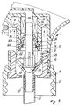
- The pump device shown in Figure 1 comprises a body A with a hollow
cylindrical handgrip 1. The lower part of thehandgrip 1 is connected to ascrew cap 3 for connecting the device to the container containing the fluid to be delivered. The upper part is provided with a preferably divergingdelivery channel 4 and two parallel spaced-apart shoulders 5 acting as lateral guides for atrigger lever 2. - The
delivery channel 4 terminates with adelivery head 6 which is rotatable to allow adjustment of the shape of the emitted flow, as described hereinafter. - With reference to Figures 2 and 3, the
trigger lever 2 is pivoted on thesupports 7 provided on the inner walls of theshoulders 5, and can move from therest position 2 in which one end of the lever is in contact with the delivery channel, to the maximum operation position 2'. Thetrigger lever 2 also comprises twoarms 32 which pass through a suitable aperture provided in the cylindrical wall of thehandgrip 1 to cooperate with acollar 8 of a mobile cylinder 9 Provided within saidhandgrip 1. - The cylinder 9 slides along the walls of a
fixed piston 10 and contracts lowerly into bottle-neck shape with a frusto-conical part 13 which when thetrigger lever 2 is not operated rests on the lower collar of a ring 11. The end 12' of the neck engages with a dip-tube 12 which dips into the fluid to be dispensed. The outer wall of the cylinder 9 comprises anaxial cavity 20 extending for a short distance prior to the bottle-neck. The ring 11 is shaped at one end in such a manner as to form a usual snap-fit with thehandgrip 1, which is shaped correspondingly thereat. On the vertical line through thecavity 20 in the cylinder 9, the handgrip and ring 11 comprise achannel 21 connected to the outside. At its other end the ring 11 comprises acollar 15 which together with the terminal part of thehandgrip 1 forms an annular recess in which thescrew cap 3 engages. - Within the mobile cylinder 9 and
piston 10, in a chamber defined by these latter, there are provided a stem-like member 14, agasket 16 and a loading orreturn spring 17. The stem-like member 14 is arranged axially to the cylinder and has itsbottom end 23 of frusto-conical shape with its base diameter greater than the rest of themember 14 and its inclination equal to the inclination of the frusto-conical part 13 of the mobile cylinder 9. - Said stem-
like member 14 also comprises arib 19, andribs 25 which extend for a certain distance from the base of theconical portion 23. - Said stem-like member also passes through the
gasket 16 to cooperate withribs 24 which act as a guide and are positioned radially in the inner wall of the fixedpiston 10 above saidgasket 16. - The
gasket 16 is substantially of frusto-conical cap shape comprising a lower divergingtoroidal band 16A in contact with the lateral walls of the mobile cylinder 9, a central step 16B externally in contact with the lower end of thefixed piston 10 and internally in contact with the end of thespring 17, and aconical terminal lip 34 which is thinner than the other portions and has its end in contact with the stem-like member 14. The toroidal band and the lip provide the seal against the cylinder 9 and against the stem-like member 14 respectively, during the operation of the pump. - The
spring 17 is retained upperly in the inner stepped part of thegasket 16 and lowerly insuitable ribs 18 provided within the conical part of the cylinder 9, but without acting directly on theconical portion 23 of the stem-like member 14. - The
delivery head 6 is snap-fitted to anannular portion 26 at the end of the variable-section delivery channel 4, and according to its position it either connects saidchannel 4, via agroove 32 and afixed channel 40 in saidannular portion 26, to one of the different-shaped orifices 31, 30 and 29, or prevents the fluid from leaving. - The operation is as follows.
- On operating the
trigger lever 2 the lever engages under thecollar 8 of the mobile cylinder to raise it and, with thedelivery head 6 set in the required position, allow the fluid to escape. More specifically, on operating thetrigger lever 2 the cylinder 9 begins to rise but theconical part 13 of the cylinder acts on theconical portion 23 of the stem-like member 14 to hermetically seal the passage to the dip-tube 12. As the cylinder 9 continues to rise, the fluid present in thechamber 22 is compressed and on reaching a given pressure causes thelip 34 of thegasket 16 to diverge so that the fluid flows into thedelivery channel 4 and from this through the delivery head to the outside. - During this stage the discharge of any air bubbles present in the
chamber 22 is facilitated by therib 19 on the stem-like member 14 which, during the last part of the stroke, diverges thelip 34 to enlarge the passage channel and balance the pressure in thechamber 22 with the pressure of the external environment. - At the end of the pumping stroke of the cylinder 9 one end of the
cavity 20 reaches the opening of thechannel 21 to balance the pressure between the fluid container and the outside. - On releasing the
trigger lever 2 the mobile cylinder 9, urged by thespring 17, moves downwards whereas the stem-like member 14 is retained by friction by thelip 34 of thegasket 16. Theconical part 23 of said stem-like member separates from theconical restriction 13 of thecylinder 14 to thus open a passageway through which the fluid present in thesuction channel 12 is drawn in. - The passageway which is created has however only a small section because, as can be seen from Figure 3, the
comical part 23 can only rise through a small distance, as saidpart 23 is restricted in its upward movement by the turns of thespring 17. - During its downward stroke, the stem-
like member 14 sucks fluid back from thedelivery channel 4, so preventing any possibility of dripping from the orifices of thedelivery head 6. At the end of its stroke the member halts and seals against thecomical restriction 13 of the cylinder 9.
Claims (15)
- A manually operated pump device for dispensing fluids from containers, particularly of the portable type for connection to said containers, for example by threaded ring nuts or capsules, characterised by comprising a mobile cylinder (9), a trigger lever (2) for operating the mobile cylinder (9), a fixed piston (10) cooperating with said cylinder (9), a delivery valve comprising a gasket (16), a suction valve comprising a stem-like member (14), said stem-like member (14) passing through said gasket (16) and cooperating with it for sealing purposes, and elastic return means (17).
- A pump device as claimed in claim 1, characterised in that said gasket (16) cooperates with the inner wall of the mobile cylinder (9) to provide the seal.
- A pump device as claimed in claim 1, characterised in that during the delivery stage of the device an end part (34) of said gasket (16) separates from the stem-like member (14) with which it cooperates.
- A pump device as claimed in claim 1, characterised in that said gasket (16) exerts a braking action on the stem-like member (14) during the return stage of the device.
- A pump device as claimed in claim 1, characterised in that a step-like portion of the gasket (16) abuts against the fixed piston (10).
- A pump device as claimed in claim 1, characterised in that said mobile cylinder (9) has an end (13) which contracts preferably to bottle-neck shape.
- A pump device as claimed in claim 1, characterised in that said stem-like member (14) has a conical end (23) arranged to cooperate with the contracting end (13) of the mobile cylinder (9).
- A pump device as claimed in claim 1, characterised in that said elastic return means (17) act between said cylinder (9) and said piston (10).
- A pump device as claimed in claims 5 and 8, characterised in that said elastic return means (17) are retained by ribs (18) provided on the inner wall of the cylinder (9) and by the inner stepped portion of the gasket (16).
- A pump device as claimed in claim 1, characterised in that the return movement of the stem-like member (14) has the effect of sucking back the liquid present in a delivery channel (4) and/or in a delivery head (6).
- A pump device as claimed in claim 1, characterised in that the mobile cylinder (9) comprises a cavity (20) in its outer lateral wall, said cavity (20) connecting the fluid container to the outside via a channel (21) at the end of the delivery stroke of said cylinder (9).
- A pump device as claimed in claim 1, characterised in that a rib (19) is provided along a certain axial portion of the stem-like member (14) to diverge the gasket (34) after a certain distance of travel.
- A pump device as claimed in claims 1 and 10, characterised in that said delivery head (6) can be positioned in different positions.
- A pump device as claimed in claim 13, characterised in that said positions of the delivery head (6) comprise a safety closure position plus further positions which enable the fluid to emerge in different forms, and in particular in jet form, in atomized form and in spray form, depending on the chosen position.
- A pump device as claimed in claims 1 and 14, characterised in that said delivery head (6) is provided with a removable security lever which locks it in the safety closure position.
Applications Claiming Priority (2)
| Application Number | Priority Date | Filing Date | Title |
|---|---|---|---|
| IT02197990A IT1243896B (en) | 1990-11-06 | 1990-11-06 | PUMP DEVICE FOR DOSING OR DISPENSING HAND-OPERATED FLUIDS. |
| IT2197990 | 1990-11-06 |
Publications (2)
| Publication Number | Publication Date |
|---|---|
| EP0484615A1 true EP0484615A1 (en) | 1992-05-13 |
| EP0484615B1 EP0484615B1 (en) | 1994-12-21 |
Family
ID=11189697
Family Applications (1)
| Application Number | Title | Priority Date | Filing Date |
|---|---|---|---|
| EP91105907A Expired - Lifetime EP0484615B1 (en) | 1990-11-06 | 1991-04-13 | Manually operated pump device for dispensing fluids |
Country Status (5)
| Country | Link |
|---|---|
| US (1) | US5222637A (en) |
| EP (1) | EP0484615B1 (en) |
| DE (1) | DE69106111T2 (en) |
| ES (1) | ES2066252T3 (en) |
| IT (1) | IT1243896B (en) |
Cited By (3)
| Publication number | Priority date | Publication date | Assignee | Title |
|---|---|---|---|---|
| EP0849000A1 (en) * | 1996-12-18 | 1998-06-24 | Monturas, S.A. | Dispenser |
| EP1188487A1 (en) * | 2000-09-12 | 2002-03-20 | Saint-Gobain Calmar Inc. | Ergonomic trigger sprayer having side saddle supports |
| WO2004099029A2 (en) * | 2003-05-05 | 2004-11-18 | The Procter & Gamble Company | Sprayer actuator, sprayer, and method of making the same |
Families Citing this family (17)
| Publication number | Priority date | Publication date | Assignee | Title |
|---|---|---|---|---|
| US5385302A (en) * | 1990-10-25 | 1995-01-31 | Contico | Low cost trigger sprayer |
| US5335858A (en) * | 1993-04-14 | 1994-08-09 | Dunning Walter B | Pump sprayer having leak preventing seals and closures |
| GB9405891D0 (en) * | 1994-03-24 | 1994-05-11 | English Glass Company The Limi | Dispenser pumps |
| US5425477A (en) * | 1994-06-29 | 1995-06-20 | Monturas, S.A. | Pump sprayer with stationary discharge |
| US5590834A (en) * | 1994-07-22 | 1997-01-07 | Contico International, Inc. | One-piece trigger sprayer housing |
| US5755384A (en) * | 1995-08-01 | 1998-05-26 | Contico International, Inc. | Dispenser with selectable discharge nozzle |
| US5664732A (en) * | 1995-08-16 | 1997-09-09 | Owens-Illinois Closure Inc. | Nozzle for pump dispensers |
| US5752629A (en) * | 1996-04-12 | 1998-05-19 | The Procter & Gamble Company | Passive venting for pump dispensing device |
| US6186366B1 (en) * | 1999-05-11 | 2001-02-13 | Calmar Inc. | Fluid dispenser with child-resistant nozzle assembly |
| US6382527B1 (en) | 2001-01-03 | 2002-05-07 | Owens-Illinois Closure Inc. | Hand-activated dispensing pump having sprayer/foamer selector wheel |
| US6446882B1 (en) | 2001-02-02 | 2002-09-10 | Owens-Illinois Closure Inc. | Trigger sprayer having sprayer/foamer selector nozzle cap |
| DE102005009294A1 (en) * | 2004-07-13 | 2006-02-16 | Ing. Erich Pfeiffer Gmbh | Donor for media |
| US20110180100A1 (en) * | 2010-01-25 | 2011-07-28 | The Dial Corporation | Multi-surface kitchen cleaning system |
| US20110180101A1 (en) * | 2010-01-25 | 2011-07-28 | The Dial Corporation | Multi-surface acidic bathroom cleaning system |
| ES2774439T3 (en) * | 2014-11-27 | 2020-07-21 | Guala Dispensing Spa | Trigger Dispensing Device with an Immovable Threaded Ring Nut |
| CN113306890B (en) * | 2016-07-08 | 2022-12-23 | 阿斯制药株式会社 | Trigger type aerosol device and aerosol cap |
| JP7292142B2 (en) * | 2019-07-31 | 2023-06-16 | 株式会社吉野工業所 | ejector |
Citations (2)
| Publication number | Priority date | Publication date | Assignee | Title |
|---|---|---|---|---|
| US4227650A (en) * | 1978-11-17 | 1980-10-14 | Ethyl Products Company | Fluid dispenser and nozzle structure |
| EP0184686A1 (en) * | 1984-12-14 | 1986-06-18 | Ing. Erich Pfeiffer GmbH & Co. KG | Piston pump for an active-substance dispenser |
Family Cites Families (13)
| Publication number | Priority date | Publication date | Assignee | Title |
|---|---|---|---|---|
| US4061247A (en) * | 1973-03-08 | 1977-12-06 | Philip Meshberg | Method of and apparatus for controlling of travel of the plunger in a dispensing pump chamber |
| US4071172A (en) * | 1976-04-07 | 1978-01-31 | Balogh Stephen M | Manually operated liquid dispenser |
| US4161288A (en) * | 1976-10-05 | 1979-07-17 | Creative Dispensing Systems, Inc. | Fluid dispenser method and apparatus |
| US4169546A (en) * | 1977-02-11 | 1979-10-02 | Vertico Industries, Inc. | Friction drag pump assembly |
| US4247048A (en) * | 1979-03-29 | 1981-01-27 | Ethyl Corporation | Dispensing nozzle |
| ES273524Y (en) * | 1983-07-14 | 1985-04-16 | Monturas Y Fornituras S.A. | LIQUID PROJECTOR GUN |
| US4591077A (en) * | 1985-01-28 | 1986-05-27 | Corsette Douglas Frank | Continuous discharge dispenser |
| AU581041B2 (en) * | 1985-12-03 | 1989-02-09 | Atsushi Tada | A manually operated trigger type dispenser |
| US4953791A (en) * | 1987-04-24 | 1990-09-04 | Atsushi Tada | Manually operated trigger type dispenser, method of assembling the same, and a spinner for use in the dispenser |
| US4898306A (en) * | 1988-01-13 | 1990-02-06 | Reseal International Limited Partnership | Collapsible container for flowable substances |
| US4982900B1 (en) * | 1988-05-16 | 1998-05-05 | William S Blake | Trigger sprayer |
| US4971227A (en) * | 1989-06-02 | 1990-11-20 | Calmar, Inc. | Manually actuated dispensing pump sprayer having a removable nozzle locking element |
| US5050779A (en) * | 1990-07-13 | 1991-09-24 | Calmar Inc. | Dispenser having child-resistant nozzle assembly |
-
1990
- 1990-11-06 IT IT02197990A patent/IT1243896B/en active IP Right Grant
-
1991
- 1991-04-13 EP EP91105907A patent/EP0484615B1/en not_active Expired - Lifetime
- 1991-04-13 DE DE69106111T patent/DE69106111T2/en not_active Expired - Lifetime
- 1991-04-13 ES ES91105907T patent/ES2066252T3/en not_active Expired - Lifetime
- 1991-04-19 US US07/687,680 patent/US5222637A/en not_active Expired - Lifetime
Patent Citations (2)
| Publication number | Priority date | Publication date | Assignee | Title |
|---|---|---|---|---|
| US4227650A (en) * | 1978-11-17 | 1980-10-14 | Ethyl Products Company | Fluid dispenser and nozzle structure |
| EP0184686A1 (en) * | 1984-12-14 | 1986-06-18 | Ing. Erich Pfeiffer GmbH & Co. KG | Piston pump for an active-substance dispenser |
Cited By (7)
| Publication number | Priority date | Publication date | Assignee | Title |
|---|---|---|---|---|
| EP0849000A1 (en) * | 1996-12-18 | 1998-06-24 | Monturas, S.A. | Dispenser |
| ES2143904A1 (en) * | 1996-12-18 | 2000-05-16 | Calmar Monturas Sa | Dispenser |
| EP1188487A1 (en) * | 2000-09-12 | 2002-03-20 | Saint-Gobain Calmar Inc. | Ergonomic trigger sprayer having side saddle supports |
| AU777805B2 (en) * | 2000-09-12 | 2004-10-28 | Saint-Gobain Calmar Inc. | Ergonomic trigger sprayer having side saddle supports |
| WO2004099029A2 (en) * | 2003-05-05 | 2004-11-18 | The Procter & Gamble Company | Sprayer actuator, sprayer, and method of making the same |
| WO2004099029A3 (en) * | 2003-05-05 | 2005-04-14 | Procter & Gamble | Sprayer actuator, sprayer, and method of making the same |
| KR100775776B1 (en) * | 2003-05-05 | 2007-11-12 | 더 프록터 앤드 갬블 캄파니 | An aerosol ergonomic sprayer |
Also Published As
| Publication number | Publication date |
|---|---|
| DE69106111D1 (en) | 1995-02-02 |
| IT9021979A0 (en) | 1990-11-06 |
| IT1243896B (en) | 1994-06-28 |
| EP0484615B1 (en) | 1994-12-21 |
| ES2066252T3 (en) | 1995-03-01 |
| IT9021979A1 (en) | 1992-05-06 |
| DE69106111T2 (en) | 1995-05-11 |
| US5222637A (en) | 1993-06-29 |
Similar Documents
| Publication | Publication Date | Title |
|---|---|---|
| EP0484615B1 (en) | Manually operated pump device for dispensing fluids | |
| US4434916A (en) | Manually operated liquid dispensing pump | |
| US5401148A (en) | Manually operated reciprocating liquid pump | |
| KR870001170B1 (en) | Liquid dispensing pump | |
| EP0309001B1 (en) | A sealing assembly and sealing collar for use in a liquid dispensing device | |
| US6021924A (en) | Manually controlled metering pump for bottles with deformable sheaths | |
| US5649649A (en) | Pump for delivering atomized liquids | |
| US4071172A (en) | Manually operated liquid dispenser | |
| CZ288430B6 (en) | Precompression pump sprayer | |
| US5794821A (en) | Reciprocating liquid pump with disc check valve for dispensing lotion and the like | |
| US4056216A (en) | Liquid dispensing pump automatically sealable against leakage | |
| US5715973A (en) | Manually operated fluid pump for dispensing lotion and the like | |
| US5850948A (en) | Finger-operable pump with piston biasing post | |
| US4503997A (en) | Dispensing pump adapted for pressure filling | |
| EP0374348A2 (en) | Improved precompression pump, for dispensing liquid products from vessels | |
| EP0342651B1 (en) | Dosing pump | |
| US5405060A (en) | Liquid spray device | |
| US5775547A (en) | Lotion dispensing pump with sealing plug for sealing pump chamber | |
| CN110650809B (en) | Spraying device and manufacturing method thereof | |
| US20080179350A1 (en) | Adapter For a Selective Inverted Actuation of Pump Dispensers | |
| US20230092170A1 (en) | All Plastic High Pressure Pump | |
| CA2268877A1 (en) | Trigger sprayer having central vent cylinder | |
| EP0484616A1 (en) | Manually operated pump device for dispensing fluids |
Legal Events
| Date | Code | Title | Description |
|---|---|---|---|
| PUAI | Public reference made under article 153(3) epc to a published international application that has entered the european phase |
Free format text: ORIGINAL CODE: 0009012 |
|
| AK | Designated contracting states |
Kind code of ref document: A1 Designated state(s): DE ES FR GB IT |
|
| 17P | Request for examination filed |
Effective date: 19920709 |
|
| 17Q | First examination report despatched |
Effective date: 19931108 |
|
| GRAA | (expected) grant |
Free format text: ORIGINAL CODE: 0009210 |
|
| AK | Designated contracting states |
Kind code of ref document: B1 Designated state(s): DE ES FR GB IT |
|
| REF | Corresponds to: |
Ref document number: 69106111 Country of ref document: DE Date of ref document: 19950202 |
|
| ET | Fr: translation filed | ||
| ITF | It: translation for a ep patent filed |
Owner name: ING. A. GIAMBROCONO & C. S.R.L. |
|
| REG | Reference to a national code |
Ref country code: ES Ref legal event code: FG2A Ref document number: 2066252 Country of ref document: ES Kind code of ref document: T3 |
|
| PLBE | No opposition filed within time limit |
Free format text: ORIGINAL CODE: 0009261 |
|
| STAA | Information on the status of an ep patent application or granted ep patent |
Free format text: STATUS: NO OPPOSITION FILED WITHIN TIME LIMIT |
|
| 26N | No opposition filed | ||
| REG | Reference to a national code |
Ref country code: GB Ref legal event code: IF02 |
|
| PGFP | Annual fee paid to national office [announced via postgrant information from national office to epo] |
Ref country code: IT Payment date: 20100326 Year of fee payment: 20 |
|
| PGFP | Annual fee paid to national office [announced via postgrant information from national office to epo] |
Ref country code: GB Payment date: 20100327 Year of fee payment: 20 |
|
| PGFP | Annual fee paid to national office [announced via postgrant information from national office to epo] |
Ref country code: FR Payment date: 20100519 Year of fee payment: 20 Ref country code: ES Payment date: 20100405 Year of fee payment: 20 |
|
| PGFP | Annual fee paid to national office [announced via postgrant information from national office to epo] |
Ref country code: DE Payment date: 20100414 Year of fee payment: 20 |
|
| REG | Reference to a national code |
Ref country code: DE Ref legal event code: R071 Ref document number: 69106111 Country of ref document: DE |
|
| REG | Reference to a national code |
Ref country code: GB Ref legal event code: PE20 Expiry date: 20110412 |
|
| PG25 | Lapsed in a contracting state [announced via postgrant information from national office to epo] |
Ref country code: GB Free format text: LAPSE BECAUSE OF EXPIRATION OF PROTECTION Effective date: 20110412 |
|
| PG25 | Lapsed in a contracting state [announced via postgrant information from national office to epo] |
Ref country code: DE Free format text: LAPSE BECAUSE OF EXPIRATION OF PROTECTION Effective date: 20110413 |
|
| REG | Reference to a national code |
Ref country code: ES Ref legal event code: FD2A Effective date: 20140826 |
|
| PG25 | Lapsed in a contracting state [announced via postgrant information from national office to epo] |
Ref country code: ES Free format text: LAPSE BECAUSE OF EXPIRATION OF PROTECTION Effective date: 20110414 |