US6186366B1 - Fluid dispenser with child-resistant nozzle assembly - Google Patents
Fluid dispenser with child-resistant nozzle assembly Download PDFInfo
- Publication number
- US6186366B1 US6186366B1 US09/309,582 US30958299A US6186366B1 US 6186366 B1 US6186366 B1 US 6186366B1 US 30958299 A US30958299 A US 30958299A US 6186366 B1 US6186366 B1 US 6186366B1
- Authority
- US
- United States
- Prior art keywords
- dispenser
- nozzle cap
- nozzle
- cap
- locking member
- Prior art date
- Legal status (The legal status is an assumption and is not a legal conclusion. Google has not performed a legal analysis and makes no representation as to the accuracy of the status listed.)
- Expired - Lifetime
Links
Images

Classifications
-
- B—PERFORMING OPERATIONS; TRANSPORTING
- B05—SPRAYING OR ATOMISING IN GENERAL; APPLYING FLUENT MATERIALS TO SURFACES, IN GENERAL
- B05B—SPRAYING APPARATUS; ATOMISING APPARATUS; NOZZLES
- B05B11/00—Single-unit hand-held apparatus in which flow of contents is produced by the muscular force of the operator at the moment of use
- B05B11/0005—Components or details
- B05B11/0027—Means for neutralising the actuation of the sprayer ; Means for preventing access to the sprayer actuation means
- B05B11/0029—Valves not actuated by pressure
-
- B—PERFORMING OPERATIONS; TRANSPORTING
- B05—SPRAYING OR ATOMISING IN GENERAL; APPLYING FLUENT MATERIALS TO SURFACES, IN GENERAL
- B05B—SPRAYING APPARATUS; ATOMISING APPARATUS; NOZZLES
- B05B11/00—Single-unit hand-held apparatus in which flow of contents is produced by the muscular force of the operator at the moment of use
- B05B11/01—Single-unit hand-held apparatus in which flow of contents is produced by the muscular force of the operator at the moment of use characterised by the means producing the flow
- B05B11/10—Pump arrangements for transferring the contents from the container to a pump chamber by a sucking effect and forcing the contents out through the dispensing nozzle
- B05B11/1042—Components or details
- B05B11/1052—Actuation means
- B05B11/1056—Actuation means comprising rotatable or articulated levers
- B05B11/1057—Triggers, i.e. actuation means consisting of a single lever having one end rotating or pivoting around an axis or a hinge fixedly attached to the container, and another end directly actuated by the user
Definitions
- the present invention relates to a fluid dispenser with a child-resistant nozzle assembly, and more particularly to a fluid dispenser having a dispenser body which rotatably supports a nozzle cap rotatable relative to the body into various ON positions such as a spray position, a stream position and an OFF position.
- the child-resistant nozzle assembly is designed to prevent children from using the dispenser in an unintended manner.
- Such dispensers present certain problems when children have access thereto.
- One such problem arises when children attempt to turn the nozzle cap from the OFF position to one of the other operative ON positions of the nozzle cap. It is therefore desirable to provide an arrangement wherein the nozzle cap can be locked against rotation relative to the dispenser body when in the OFF position, and further wherein the locking action will occur automatically when the nozzle cap is turned to such position. Additionally, unlocking of the nozzle cap should be easy for an adult to accomplish, yet very difficult if not virtually impossible for a child.
- U.S. Pat. No. 4,516,695 discloses a construction wherein a locking member automatically moves into locking position when the nozzle cap is rotated into an OFF position.
- a flex arm member extends downwardly beneath the lower or underside of the nozzle cap and nozzle end of the dispenser body.
- the flex arm is adapted to be pulled rearwardly of the device by the trigger finger of a user to move the locking member into a release position when the device is held in its normal position within the user's hand.
- the nozzle cap can then be rotated into the desired position.
- the disadvantage of such structure is that the flex arm cannot be readily seen by the user, and access to the flex arm is not convenient. Therefore, this prior art device is difficult even for an adult to use.
- the flex arm can be easily moved rearwardly by the tip of a finger from a point in front of the nozzle cap so that accidental release of the locking mechanism is possible.
- a further problem encountered with nozzle caps of the type discussed above is that children have a tendency to suck on the outer end of the nozzle. This may result in some of the fluid in the dispenser entering into the child's mouth. This can be a dangerous situation since many of the fluids contained in such dispensers could if ingested make a child ill. It is noted that even if the nozzle is in OFF position and the dispenser has been previously used, there may be some residual dispenser fluid in the dispenser downstream of its shut-off valve. It is therefore an object of the invention to provide means for preventing children from sucking any significant amount of dispenser fluid from the discharge opening of the nozzle cap.
- the present invention provides an improved dispenser wherein at least one locking member is movably supported by the dispenser body and extends laterally from one side portion of the body so as to be in full view when the dispenser is held in the hand of a user.
- the locking member engages a flat surface or recess in the nozzle cap to positively lock the nozzle cap against rotation relative to the dispenser body.
- the locking member is integral with the body to form a flexible connector hinge which permits rocking movement of the locking member relative to the body and further ensures that the locking member will automatically move into its locking position when the nozzle is rotated to its OFF position.
- the “dispenser body” as described and claimed refers to the pump body with or without an outer shroud connected thereto.
- the locking member(s) may be integrally connected with the pump body or with the shroud, in accordance with the invention.
- the locking member is integrally connected with the pump body.
- the shroud is provided with slot means therein adjacent the nozzle end of the body for receiving a portion of the locking member and allowing it to rock back and forth between its locking and unlocked positions.
- the locking member may be integrally connected with the shroud in accordance with another embodiment.
- the dispenser may also have a pair of locking members mounted at opposite sides of the dispenser to provide a more positive locking action. These opposing locking members may be simultaneously moved into release or unlocking position by squeezing the two locking members between two fingers of the user's hand.
- the nozzle cap may be provided with passage means in addition to the discharge passage means formed therein.
- This additional passage means may take the form of a plurality of passages or may be a single passage, as so desired.
- the additional passage means which provides communication between a portion of the nozzle cap near the discharge opening thereof and ambient air, may be located within the confines of the outer periphery of the nozzle cap or may be located externally so as to lie on an outer wall of the cap.
- the locking member arrangement for preventing the nozzle cap from rotating from its OFF position and the additional passage means provided in the nozzle cap for preventing undesired sucking of fluid from the dispenser form two different features which can be employed individually in nozzle caps, or the two features may be employed in the same nozzle cap to provide both forms of child resistance.
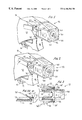
- FIG. 1 is a top perspective view of a first form of the invention shown in one operative position;
- FIG. 2 is a view similar to FIG. 1 showing a second operative position
- FIG. 3 is a top view, partly broken away, of the device shown in FIG. 1;
- FIG. 3A is a view similar to FIG. 3 showing the locking member alternatively on the pump shroud
- FIG. 4 is a side view of another form of the invention.
- FIG. 5 is a front view of a portion of the device shown in FIG. 4;
- FIG. 6 is a view of the rear face of the nozzle cap shown in FIG. 4;
- FIG. 7 is a sectional view, partly broken away, of the nozzle cap, taken on line 7 — 7 of FIG. 6, and illustrating the nozzle cap mounted on the associated pump body;
- FIG. 8 is a view similar to FIG. 4 of another embodiment.
- FIG. 9 is a front view of the device of FIG. 8 .
- FIGS. 1-3 Part of a fluid dispenser 10 is shown in FIGS. 1 and 2 in the form of a manually operated trigger dispenser including a conventional pump body having a nozzle end 11 as seen in FIG. 3, and a pair of side portions 12 and 14 which are joined by a top portion (not shown).
- the pump body has a pump cylinder 16 containing a reciprocable pump piston 17 which is manually reciprocated in known manner by a trigger actuator 18 hingedly mounted on the pump body.
- a conventional shroud 20 may be supported in overlying relationship and connected to the pump body in some normal manner, although the invention can also be utilized with a dispenser which does not have a shroud.
- a nozzle cap 22 is rotatably supported at the nozzle end 11 of the pump body.
- the nozzle cap may have a rectangular external configuration as seen in FIGS. 1 and 2 to facilitate manual rotation of the cap.
- the cap has markings on two sides thereof such as OFF on a pair of opposed walls. The other two opposed walls are illustrated as having ON markings for the purpose of describing the invention, but in actuality will have markings thereon such as “STREAM ” and “SPRAY”.
- the internal mechanism of the nozzle cap and the manner in which the nozzle is mounted on the pump body may be similar to that shown in U.S. Pat. No. 4,706,888, the disclosure of which is incorporated by reference.
- the internal details of the nozzle cap 22 as well as the manner in which the nozzle cap is rotatably mounted are shown in FIG. 7 where a similar nozzle cap is illustrated.
- the nozzle cap includes a front face 30 having a discharge opening 32 located at the center as in the normal manner. Four passages 34 are respectively formed at the four corners of the front face for a purpose which will be described hereinafter.
- the nozzle cap has a laterally extending peripheral flange 36 formed at the end of the nozzle cap adjacent the nozzle end of the pump body. The flange is provided with a pair of notches 38 and 40 as seen in FIG. 3, only notch 38 being visible in FIGS. 1 and 2.
- a pair of locking members 50 and 52 are molded integral with the pump body side portions 12 and 14 to form flexible connectors 54 and 56 respectively which permit rocking movement of the two locking members relative to the pump body.
- the flexible connectors are formed at intermediate points along the locking members 50 and 52 to define first ends 50 ′ and 52 ′ respectively which are received with the recesses in the flange on the nozzle cap and second ends 50 ′′ and 52 ′′ respectively which extend rearwardly of the nozzle end of the pump body so that they can be manually engaged to release the locking members from the notches.
- the pump body is formed of plastic material, and the flexible connectors provide resilient connections between the pump body and the locking members which normally bias the locking members into the locking position shown in FIGS. 1 and 3.
- the locking ends 50 ′ and 52 ′ snugly fit within the notches 38 and 40 with the flat sides thereof facing one another so as to provide a positive locking action preventing rotation of the nozzle cap with respect to the pump body.
- the locking members are in full view when the dispenser is held in the hand of a user and are readily accessible when the locking members are in the position shown in FIGS. 1 and 3.
- the locking members may alternatively be integrally molded with side portions of shroud 20 which overlies the pump body which is connected thereto in a manner known in the art.
- the ends 50 ′′ and 52 ′′ of the locking members can be squeezed between two fingers to move the opposite ends 50 ′ and 52 ′ of the locking members out of the notches, whereupon the nozzle cap can be rotated to an ON position where the ON marking faces upwardly.
- the locking members will be automatically moved back into the position shown in FIGS. 1 and 3.
- Such may be provided as by chamfers 37 leading into notches 38 and 40 , as shown in FIGS. 1 and 2.
- a dispenser 60 is provided with a trigger actuator 62 which operates in the usual manner.
- a nozzle cap 64 has a front face 66 and a rear face 68 which is slightly spaced from the nozzle end face 70 of the pump body.
- the nozzle cap is rotatably supported on a tubular outlet member 72 of the dispenser by a snap fit produced between an external rib 74 formed on member 72 and an internal rib 76 formed within cap skirt 78 .
- An integral cylindrical sleeve 82 formed on the nozzle cap has discharge passage means formed therein in the form of three equally spaced passages 84 which are in communication with a discharge opening 86 formed at the center of front face 66 . Additional passage means is provided within the nozzle cap for providing communication between a portion of the nozzle cap near the discharge opening and ambient air.
- One or more passages may be provided, and as illustrated in FIG. 5, four passages 90 are provided. These passages correspond to the passages 34 described in connection with FIGS. 1 and 2 of the drawings.
- one end 92 of each passage opens at front face 76 at a position which is near the discharge opening 86 , and the other end 94 of each passage is in communication with the rear face 68 of the nozzle cap. It is noted that since the rear face of the nozzle cap is spaced from the outer end face of the pump body, air can freely flow between these faces and thence forwardly through passages 90 to the front face of the nozzle cap.
- the child's mouth will surround the nozzle cap so that when suction is applied to the nozzle cap, air will be drawn through the additional passage means 90 , thereby preventing any significant amount of fluid from being drawn into the mouth of the child through the discharge opening 86 .
- the air passage or passages 90 may be formed within the outer periphery of the nozzle cap as described with reference to FIGS. 4 to 7 , or may be formed externally of the nozzle cap periphery as shown in FIGS. 8 and 9.
- a conduit 100 is provided on one or more of the outer faces of cap 64 , the conduit extending between front and rear faces 66 , 68 , and defining an air passage 102 extending between faces 66 , 68 .
- the conduit 100 is shown in triangular in FIGS. 8 and 9, it can be of any alternate shape such a rectangular, circular, oval etc., without departing from the invention.
- Air passage or passages 102 function in the same manner as described with reference to FIGS. 4 to 7 .
- the dispenser shown in FIGS. 1-3 may be employed without passages 34 to provide only the single child-resistant feature of means for locking the nozzle cap against rotation with respect to the pump body.
- the dispenser shown in FIGS. 1-3 can also employ the passages 34 which are similar to passages 90 as discussed in connection with FIGS. 4-7 in which case passages 34 open through the rear face of nozzle cap 22 to provide communication between the ends of passages 34 at the front face 30 of the nozzle cap and ambient air.
- the additional passage means is employed with the construction shown in FIGS. 1 and 2
- the rear face of the nozzle cap will be spaced from the outer end face of the pump body.
- the device shown in FIGS. 1-3 may incorporate two child-resistant features into one structure.
- FIGS. 4-7 and 8 and 9 can be utilized with the single child resistant feature of preventing a child from sucking fluid from the dispenser when sucking on the nozzle cap.
Abstract
Description
Claims (22)
Priority Applications (1)
| Application Number | Priority Date | Filing Date | Title |
|---|---|---|---|
| US09/309,582 US6186366B1 (en) | 1999-05-11 | 1999-05-11 | Fluid dispenser with child-resistant nozzle assembly |
Applications Claiming Priority (1)
| Application Number | Priority Date | Filing Date | Title |
|---|---|---|---|
| US09/309,582 US6186366B1 (en) | 1999-05-11 | 1999-05-11 | Fluid dispenser with child-resistant nozzle assembly |
Publications (1)
| Publication Number | Publication Date |
|---|---|
| US6186366B1 true US6186366B1 (en) | 2001-02-13 |
Family
ID=23198807
Family Applications (1)
| Application Number | Title | Priority Date | Filing Date |
|---|---|---|---|
| US09/309,582 Expired - Lifetime US6186366B1 (en) | 1999-05-11 | 1999-05-11 | Fluid dispenser with child-resistant nozzle assembly |
Country Status (1)
| Country | Link |
|---|---|
| US (1) | US6186366B1 (en) |
Cited By (20)
| Publication number | Priority date | Publication date | Assignee | Title |
|---|---|---|---|---|
| US6669058B1 (en) * | 2002-10-29 | 2003-12-30 | Saint-Gobain Calmar Inc. | Trigger sprayer with nozzle trigger lock |
| US6752296B1 (en) * | 2003-03-10 | 2004-06-22 | Saint-Gobain Calmar Inc. | Bi-injection trigger sprayer nozzle cap |
| US20040251316A1 (en) * | 2003-06-10 | 2004-12-16 | Stark Jeffrey P. | Child resistant indexing nozzle for a trigger sprayer |
| US20050082311A1 (en) * | 2003-10-16 | 2005-04-21 | Good Robert J. | Child-resistant trigger sprayer |
| US7036689B1 (en) | 2002-04-22 | 2006-05-02 | Continental Afa Dispensing Company | Child-resistant trigger sprayer |
| US20070056991A1 (en) * | 2005-09-13 | 2007-03-15 | Saint-Gobain Calmar, Inc. | Child resistant manually actuated dispensing device |
| US20070228187A1 (en) * | 2006-03-07 | 2007-10-04 | Continentalafa Dispensing Company | Trigger Sprayer With Child Resistant Indexing Nozzle |
| US20080308655A1 (en) * | 2007-06-13 | 2008-12-18 | Jian Jun Yuan | Trigger Sprayer Structure with Children Protection Functions |
| US20100320237A1 (en) * | 2009-06-17 | 2010-12-23 | Accredit Innovations Limited | Fluid dispensing apparatus with lockable actuator |
| USD650046S1 (en) | 2011-03-01 | 2011-12-06 | Smg Brands, Inc. | Sprayer |
| USD670982S1 (en) | 2011-03-01 | 2012-11-20 | Smg Brands, Inc. | Applicator |
| USD681470S1 (en) | 2010-01-08 | 2013-05-07 | Oms Investments, Inc. | Dispensing container |
| US20130341362A1 (en) * | 2011-06-16 | 2013-12-26 | Obrist Closures Switzerland Gmbh | Trigger Pump Dispenser |
| US20140076935A1 (en) * | 2012-03-27 | 2014-03-20 | Young Joon Kim | Pump safety device for various containers |
| USD708301S1 (en) | 2013-03-15 | 2014-07-01 | Oms Investments, Inc. | Liquid sprayer |
| US20150165454A1 (en) * | 2012-07-11 | 2015-06-18 | Canyon Europe Ltd. | Trigger sprayer |
| EP3097983A4 (en) * | 2014-01-22 | 2018-01-17 | Canyon Corporation | Trigger-type sprayer |
| US9980430B2 (en) | 2011-03-01 | 2018-05-29 | Oms Investments, Inc. | Ready-to-use hose end sprayer |
| US10022742B2 (en) | 2011-03-01 | 2018-07-17 | Oms Investments, Inc. | Applicator with collapsible wand |
| USD980069S1 (en) | 2020-07-14 | 2023-03-07 | Ball Corporation | Metallic dispensing lid |
Citations (10)
| Publication number | Priority date | Publication date | Assignee | Title |
|---|---|---|---|---|
| US4204614A (en) * | 1978-09-28 | 1980-05-27 | Diamond International Corporation | Fluid dispenser having a spring biased locking mechanism for a safety nozzle cap |
| US4516695A (en) | 1981-02-09 | 1985-05-14 | The Afa Corporation | Child-resistant liquid dispenser sprayer or like apparatus |
| US4706888A (en) | 1986-07-11 | 1987-11-17 | Calmar, Inc. | Multi-purpose nozzle assembly |
| US5050779A (en) * | 1990-07-13 | 1991-09-24 | Calmar Inc. | Dispenser having child-resistant nozzle assembly |
| US5088628A (en) * | 1990-07-13 | 1992-02-18 | Calmar Inc. | Dispenser having child-resistant nozzle assembly |
| US5222637A (en) * | 1990-11-06 | 1993-06-29 | Coster Tecnologie Speciali S.P.A. | Manually operated pump device for dispensing fluids |
| US5535952A (en) * | 1993-08-11 | 1996-07-16 | Tada; Tetsuya | Safety mechanism for a manually operated trigger activated dispenser |
| US5662246A (en) | 1995-10-03 | 1997-09-02 | Owens-Illinois Closure Inc. | Tamper-deterrent nozzle for pump dispensers |
| US5687880A (en) | 1996-04-24 | 1997-11-18 | Afa Products, Inc. | Child lock nozzle cap assembly |
| US5848733A (en) * | 1996-11-12 | 1998-12-15 | Continental Sprayers International, Inc. | Manually operated pump dispenser having child-resistant nozzle |
-
1999
- 1999-05-11 US US09/309,582 patent/US6186366B1/en not_active Expired - Lifetime
Patent Citations (10)
| Publication number | Priority date | Publication date | Assignee | Title |
|---|---|---|---|---|
| US4204614A (en) * | 1978-09-28 | 1980-05-27 | Diamond International Corporation | Fluid dispenser having a spring biased locking mechanism for a safety nozzle cap |
| US4516695A (en) | 1981-02-09 | 1985-05-14 | The Afa Corporation | Child-resistant liquid dispenser sprayer or like apparatus |
| US4706888A (en) | 1986-07-11 | 1987-11-17 | Calmar, Inc. | Multi-purpose nozzle assembly |
| US5050779A (en) * | 1990-07-13 | 1991-09-24 | Calmar Inc. | Dispenser having child-resistant nozzle assembly |
| US5088628A (en) * | 1990-07-13 | 1992-02-18 | Calmar Inc. | Dispenser having child-resistant nozzle assembly |
| US5222637A (en) * | 1990-11-06 | 1993-06-29 | Coster Tecnologie Speciali S.P.A. | Manually operated pump device for dispensing fluids |
| US5535952A (en) * | 1993-08-11 | 1996-07-16 | Tada; Tetsuya | Safety mechanism for a manually operated trigger activated dispenser |
| US5662246A (en) | 1995-10-03 | 1997-09-02 | Owens-Illinois Closure Inc. | Tamper-deterrent nozzle for pump dispensers |
| US5687880A (en) | 1996-04-24 | 1997-11-18 | Afa Products, Inc. | Child lock nozzle cap assembly |
| US5848733A (en) * | 1996-11-12 | 1998-12-15 | Continental Sprayers International, Inc. | Manually operated pump dispenser having child-resistant nozzle |
Cited By (44)
| Publication number | Priority date | Publication date | Assignee | Title |
|---|---|---|---|---|
| US7036689B1 (en) | 2002-04-22 | 2006-05-02 | Continental Afa Dispensing Company | Child-resistant trigger sprayer |
| US6669058B1 (en) * | 2002-10-29 | 2003-12-30 | Saint-Gobain Calmar Inc. | Trigger sprayer with nozzle trigger lock |
| US6752296B1 (en) * | 2003-03-10 | 2004-06-22 | Saint-Gobain Calmar Inc. | Bi-injection trigger sprayer nozzle cap |
| CN100368095C (en) * | 2003-03-10 | 2008-02-13 | 圣-戈宾卡尔玛公司 | Nozzle cover of trigger atomizer with double injection mould |
| KR100744871B1 (en) | 2003-06-10 | 2007-08-01 | 콘티넨탈 에이에프에이 디스펜싱 컴퍼니 | Child resistant indexing nozzle for a trigger sprayer |
| US20040251316A1 (en) * | 2003-06-10 | 2004-12-16 | Stark Jeffrey P. | Child resistant indexing nozzle for a trigger sprayer |
| US6845922B2 (en) * | 2003-06-10 | 2005-01-25 | Continental Afa Dispensing Company | Child resistant indexing nozzle for a trigger sprayer |
| WO2005003020A3 (en) * | 2003-06-10 | 2005-11-03 | Continental Afa Dispensing Co | Child resistant indexing nozzle for a trigger sprayer |
| EP1631483A2 (en) * | 2003-06-10 | 2006-03-08 | Continental Afa Dispensing Company | Child resistant indexing nozzle for a trigger sprayer |
| EP1631483A4 (en) * | 2003-06-10 | 2008-08-20 | Continental Afa Dispensing Co | Child resistant indexing nozzle for a trigger sprayer |
| US20050082311A1 (en) * | 2003-10-16 | 2005-04-21 | Good Robert J. | Child-resistant trigger sprayer |
| US7032777B2 (en) | 2003-10-16 | 2006-04-25 | Saint-Gobain Calmar, Inc. | Child-resistant trigger sprayer |
| WO2007032952A2 (en) * | 2005-09-13 | 2007-03-22 | Meadwestvaco Corporation | Child resistant manually actuated dispensing device |
| WO2007032952A3 (en) * | 2005-09-13 | 2007-05-03 | Meadwestvaco Corp | Child resistant manually actuated dispensing device |
| US20070056991A1 (en) * | 2005-09-13 | 2007-03-15 | Saint-Gobain Calmar, Inc. | Child resistant manually actuated dispensing device |
| US7472806B2 (en) | 2005-09-13 | 2009-01-06 | Meadwestvaco Calmar, Inc. | Child resistant manually actuated dispensing device |
| US20070228187A1 (en) * | 2006-03-07 | 2007-10-04 | Continentalafa Dispensing Company | Trigger Sprayer With Child Resistant Indexing Nozzle |
| WO2007103922A3 (en) * | 2006-03-07 | 2008-06-26 | Continentalafa Dispensing Co | Trigger sprayer with child resistant indexing nozzle |
| US20080308655A1 (en) * | 2007-06-13 | 2008-12-18 | Jian Jun Yuan | Trigger Sprayer Structure with Children Protection Functions |
| US20100320237A1 (en) * | 2009-06-17 | 2010-12-23 | Accredit Innovations Limited | Fluid dispensing apparatus with lockable actuator |
| USD681470S1 (en) | 2010-01-08 | 2013-05-07 | Oms Investments, Inc. | Dispensing container |
| US11338313B2 (en) | 2011-03-01 | 2022-05-24 | Oms Investments, Inc. | Applicator with collapsible wand |
| USD999033S1 (en) | 2011-03-01 | 2023-09-19 | Oms Investments, Inc. | Applicator |
| USD852593S1 (en) | 2011-03-01 | 2019-07-02 | Oms Investments, Inc. | Applicator |
| US10022742B2 (en) | 2011-03-01 | 2018-07-17 | Oms Investments, Inc. | Applicator with collapsible wand |
| USD779898S1 (en) | 2011-03-01 | 2017-02-28 | Oms Investments, Inc. | Applicator |
| USD670982S1 (en) | 2011-03-01 | 2012-11-20 | Smg Brands, Inc. | Applicator |
| USD736577S1 (en) | 2011-03-01 | 2015-08-18 | Oms Investments, Inc. | Applicator |
| US11744171B2 (en) | 2011-03-01 | 2023-09-05 | Oms Investments, Inc. | Ready-to-use hose end sprayer |
| US9980430B2 (en) | 2011-03-01 | 2018-05-29 | Oms Investments, Inc. | Ready-to-use hose end sprayer |
| USD650046S1 (en) | 2011-03-01 | 2011-12-06 | Smg Brands, Inc. | Sprayer |
| USD864679S1 (en) | 2011-03-01 | 2019-10-29 | Oms Investments, Inc. | Applicator |
| USD797529S1 (en) | 2011-03-01 | 2017-09-19 | Oms Investments, Inc. | Applicator |
| US9132441B2 (en) * | 2011-06-16 | 2015-09-15 | Obrist Closures Switzerland Gmbh | Trigger pump dispenser with on/off indicator |
| US20130341362A1 (en) * | 2011-06-16 | 2013-12-26 | Obrist Closures Switzerland Gmbh | Trigger Pump Dispenser |
| US10173234B2 (en) | 2011-06-16 | 2019-01-08 | Obrist Closures Switzerland Gmbh | Trigger pump dispenser with interchangeable piston |
| US20140076935A1 (en) * | 2012-03-27 | 2014-03-20 | Young Joon Kim | Pump safety device for various containers |
| US9237830B2 (en) * | 2012-03-27 | 2016-01-19 | Yong Jun Kim | Pump safety device for various containers |
| US20150165454A1 (en) * | 2012-07-11 | 2015-06-18 | Canyon Europe Ltd. | Trigger sprayer |
| US9707576B2 (en) * | 2012-07-11 | 2017-07-18 | Syngenta Participations Ag | Trigger sprayer |
| USD708301S1 (en) | 2013-03-15 | 2014-07-01 | Oms Investments, Inc. | Liquid sprayer |
| US10549296B2 (en) | 2014-01-22 | 2020-02-04 | Canyon Corporation | Trigger-type sprayer |
| EP3097983A4 (en) * | 2014-01-22 | 2018-01-17 | Canyon Corporation | Trigger-type sprayer |
| USD980069S1 (en) | 2020-07-14 | 2023-03-07 | Ball Corporation | Metallic dispensing lid |
Similar Documents
| Publication | Publication Date | Title |
|---|---|---|
| US6186366B1 (en) | Fluid dispenser with child-resistant nozzle assembly | |
| US5228600A (en) | Child resistant nozzle for trigger sprayer | |
| US7249692B2 (en) | Dispenser with lock | |
| US4838460A (en) | Product dispenser having actuator locking collar and shroud | |
| EP0256854B1 (en) | Dispenser | |
| US5169032A (en) | Tamper evident sprayer/nozzle assembly | |
| US4441633A (en) | Child resistant trigger pump | |
| US20060113329A1 (en) | Dispenser with lock | |
| US6003738A (en) | Child-resistant rotating lock for manually operated pump dispenser | |
| US20070228187A1 (en) | Trigger Sprayer With Child Resistant Indexing Nozzle | |
| JP2857032B2 (en) | Manual trigger type dispenser and its nozzle | |
| US5161716A (en) | Dispenser having child-resistant nozzle assembly | |
| CA1094254A (en) | Portable toilets | |
| US7032777B2 (en) | Child-resistant trigger sprayer | |
| EP0767007B1 (en) | Tamper-deterrent nozzle for pump dispensers | |
| US5649646A (en) | Child resistant nozzle | |
| JP4198272B2 (en) | Trigger type liquid ejector | |
| US7036689B1 (en) | Child-resistant trigger sprayer | |
| JP3770441B2 (en) | Trigger type liquid ejector | |
| JPH0513420Y2 (en) | ||
| JP3730018B2 (en) | Trigger type liquid jet pump | |
| JP3780440B2 (en) | Trigger type liquid jet pump | |
| JP2011178433A (en) | Trigger spray | |
| JP2529236Y2 (en) | pump | |
| JP3780443B2 (en) | Trigger type liquid jet pump |
Legal Events
| Date | Code | Title | Description |
|---|---|---|---|
| AS | Assignment |
Owner name: CALMAR INC., CALIFORNIA Free format text: ASSIGNMENT OF ASSIGNORS INTEREST;ASSIGNORS:GOOD, ROBERT J.;DIMAGGIO, PHILLIP J.;REEL/FRAME:009965/0851 Effective date: 19990426 |
|
| STCF | Information on status: patent grant |
Free format text: PATENTED CASE |
|
| FPAY | Fee payment |
Year of fee payment: 4 |
|
| FPAY | Fee payment |
Year of fee payment: 8 |
|
| FPAY | Fee payment |
Year of fee payment: 12 |
|
| AS | Assignment |
Owner name: MEADWESTVACO CALMAR, INC., VIRGINIA Free format text: CHANGE OF NAME;ASSIGNOR:SAINT-GOBAIN CALMAR INC.;REEL/FRAME:041391/0564 Effective date: 20060705 Owner name: WESTROCK DISPENSING SYSTEMS, INC., GEORGIA Free format text: CHANGE OF NAME;ASSIGNOR:MEADWESTVACO CALMAR, INC.;REEL/FRAME:041391/0567 Effective date: 20150818 Owner name: SAINT-GOBAIN CALMAR INC., VIRGINIA Free format text: CHANGE OF NAME;ASSIGNOR:CALMAR INC.;REEL/FRAME:041391/0557 Effective date: 20001110 |