US5697556A - Liquid dispenser having discharge valve assembly - Google Patents
Liquid dispenser having discharge valve assembly Download PDFInfo
- Publication number
- US5697556A US5697556A US08/575,722 US57572295A US5697556A US 5697556 A US5697556 A US 5697556A US 57572295 A US57572295 A US 57572295A US 5697556 A US5697556 A US 5697556A
- Authority
- US
- United States
- Prior art keywords
- valve
- valve housing
- liquid
- moveable
- fluid
- Prior art date
- Legal status (The legal status is an assumption and is not a legal conclusion. Google has not performed a legal analysis and makes no representation as to the accuracy of the status listed.)
- Expired - Fee Related
Links
Images

Classifications
-
- B—PERFORMING OPERATIONS; TRANSPORTING
- B05—SPRAYING OR ATOMISING IN GENERAL; APPLYING FLUENT MATERIALS TO SURFACES, IN GENERAL
- B05B—SPRAYING APPARATUS; ATOMISING APPARATUS; NOZZLES
- B05B11/00—Single-unit hand-held apparatus in which flow of contents is produced by the muscular force of the operator at the moment of use
- B05B11/0005—Components or details
- B05B11/0062—Outlet valves actuated by the pressure of the fluid to be sprayed
- B05B11/0075—Two outlet valves being placed in a delivery conduit, one downstream the other
-
- B—PERFORMING OPERATIONS; TRANSPORTING
- B05—SPRAYING OR ATOMISING IN GENERAL; APPLYING FLUENT MATERIALS TO SURFACES, IN GENERAL
- B05B—SPRAYING APPARATUS; ATOMISING APPARATUS; NOZZLES
- B05B11/00—Single-unit hand-held apparatus in which flow of contents is produced by the muscular force of the operator at the moment of use
- B05B11/0005—Components or details
- B05B11/0062—Outlet valves actuated by the pressure of the fluid to be sprayed
- B05B11/0064—Lift valves
-
- B—PERFORMING OPERATIONS; TRANSPORTING
- B05—SPRAYING OR ATOMISING IN GENERAL; APPLYING FLUENT MATERIALS TO SURFACES, IN GENERAL
- B05B—SPRAYING APPARATUS; ATOMISING APPARATUS; NOZZLES
- B05B11/00—Single-unit hand-held apparatus in which flow of contents is produced by the muscular force of the operator at the moment of use
- B05B11/01—Single-unit hand-held apparatus in which flow of contents is produced by the muscular force of the operator at the moment of use characterised by the means producing the flow
- B05B11/10—Pump arrangements for transferring the contents from the container to a pump chamber by a sucking effect and forcing the contents out through the dispensing nozzle
- B05B11/1001—Piston pumps
- B05B11/1009—Piston pumps actuated by a lever
- B05B11/1011—Piston pumps actuated by a lever without substantial movement of the nozzle in the direction of the pressure stroke
-
- B—PERFORMING OPERATIONS; TRANSPORTING
- B05—SPRAYING OR ATOMISING IN GENERAL; APPLYING FLUENT MATERIALS TO SURFACES, IN GENERAL
- B05B—SPRAYING APPARATUS; ATOMISING APPARATUS; NOZZLES
- B05B11/00—Single-unit hand-held apparatus in which flow of contents is produced by the muscular force of the operator at the moment of use
- B05B11/01—Single-unit hand-held apparatus in which flow of contents is produced by the muscular force of the operator at the moment of use characterised by the means producing the flow
- B05B11/10—Pump arrangements for transferring the contents from the container to a pump chamber by a sucking effect and forcing the contents out through the dispensing nozzle
- B05B11/1038—Pressure accumulation pumps, i.e. pumps comprising a pressure accumulation chamber
- B05B11/104—Pressure accumulation pumps, i.e. pumps comprising a pressure accumulation chamber the outlet valve being opened by pressure after a defined accumulation stroke
Definitions
- This invention relates to a liquid dispenser and more particularly to a pump-type dispenser.
- a pressure buildup sprayer is a general type of sprayer in which liquid dispensed from the sprayer is raised to a certain pressure level before it is dispensed from the sprayer.
- a sprayer includes a dispenser body having a manually operated pump which draws liquid from a source of liquid (e.g., a container) and dispenses it through a nozzle via a liquid flow path in the dispenser body.
- a pressure regulating valve e.g., a pressure buildup valve
- the pressure regulating valve When the fluid pressure reaches the minimum level, the pressure regulating valve opens to permit liquid to be dispensed through the pressure regulating valve and out the nozzle.
- the pressure regulating valve typically has a moveable member within the dispenser body which is moveable in and out of seating engagement with a valve seat formed in the dispenser body. Such pressure regulating valve also has a spring for urging the moveable member toward the valve seat.
- a disadvantage of such a sprayer is that the dispenser body must be shaped to accommodate the pressure regulating valve and generally must be formed with components of the valve, such as a valve seat. Forming a valve body to have some of the parts of the valve is often difficult and expensive and requires the use of complex molding techniques. It is also difficult to assemble the various parts of the valve in the dispenser body.
- the dispenser body is either configured for accommodating only a pressure buildup check valve or a regular check valve.
- different dispenser body types must be made to accommodate both types of sprayers.
- an improved dispenser the provision of such a dispenser having a dispenser body of relatively simple construction; the provision of such a dispenser having a dispenser body configured for accommodating different types of check valves; the provision of such a dispenser having a dispenser body of a shape which may be manufactured relatively easily; the provision of such a dispenser which is relatively easy to assemble; the provision of such a dispenser having a check valve in which all of the parts of the check valve are separate from the dispenser body; and the provision of such a dispenser having a valve housing separate from the dispenser body.
- a liquid dispenser of the present invention comprises a dispenser body and a valve housing.
- the dispenser body has a pump mechanism, an intake port adapted for fluid communication with a source of liquid, an intake liquid flow path providing fluid communication between the intake port and the pump mechanism, and a first check valve in the intake liquid flow path.
- the first check valve is configured for permitting fluid flow from the intake port to the pump mechanism and for checking fluid flow from the pump mechanism to the intake port.
- the dispenser body further comprises a discharge conduit and a discharge liquid flow path providing fluid communication between the pump mechanism and discharge conduit.
- the discharge conduit has a downstream end through which dispensed liquid exits the discharge conduit.
- the valve housing has first and second portions, a fluid passageway within the first and second portions, and a discharge port in the second portion and in fluid communication with the fluid passageway.
- the first portion of the valve housing is attached to the dispenser body adjacent the downstream end of the discharge conduit so that the passageway of the valve housing is in fluid communication with the discharge conduit.
- the liquid dispenser further includes a second check valve positioned in the passageway of the valve housing.
- the second check valve is moveable between a closed position for blocking fluid flow between the pump mechanism and discharge port and an open position for permitting fluid to flow from the pump chamber through the discharge port via the discharge liquid flow path and the fluid passageway of the valve housing.
- the liquid dispenser is a trigger sprayer.
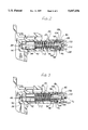
- FIG. 1 is a side elevational view, in section, of a liquid dispenser of the present invention having a dispenser body and a valve housing inserted in the dispenser body;
- FIG. 2 is an enlarged side elevational view, in section, of the valve housing of FIG. 1 separated from the dispenser body and showing a moveable valve member of a pressure buildup valve in a closed (seated) position;
- FIG. 3 is an enlarged side elevational view similar to the view of FIG. 2 except showing the valve member in an open (unseated) position.
- a spray-type dispenser of the present invention is indicated in its entirety by the reference numeral 20.
- the dispenser 20 comprises a dispenser body, generally indicated at 22, a valve housing, generally indicated at 26, and a pressure regulating valve (i.e., pressure buildup valve), generally indicated at 28.
- the dispenser body 22 comprises an upper housing member, generally indicated at 30, a lower housing member, generally indicated at 32, and a ball-type check valve, generally indicated at 34.
- each of these components is of a polymeric material. However, it is to be understood that some or all of the components may be of other materials without departing from the scope of this invention.
- the upper housing member 30 of the dispenser body 22 includes a cylindric formation (wall) 36, a disc-shaped back wall 38 substantially closing one end (i.e., the right end as viewed in FIG. 1) of the cylindric wall, a generally cylindric vertical formation 40 adjacent the disc-shaped back wall, and a horizontal tubular portion 42 extending forward from the vertical formation.
- the cylindric wall 36 includes a generally cylindric inner surface 44.
- the inner surface 44 of the cylindric wall 36 and the disc-shaped back wall 38 define a pump chamber 46 open at one end (i.e., its left end as viewed in FIG. 1) for slidably receiving a pump piston 48.
- the pump chamber 46 and pump piston 48 constitute a pump mechanism 50 of the dispenser body 22.
- the vertical formation 40 of the upper housing member 30 has a vertical bore 52 extending upward from the bottom of the vertical formation 40.
- a lower end of the vertical bore 52 receives the lower housing member 32 of the dispenser body 22.
- the lower housing member 32 has a generally cylindric column 54 extending upward into the vertical bore 52 in sealing engagement with the vertical formation 40.
- an upper end portion 56 of the cylindric column 54 is of reduced diameter to define a cylindric gap 58 between the cylindric column and the surface of the vertical bore 52.
- the cylindric gap 58 is in fluid communication with the pump chamber 46 via a lateral opening 60 through the disc-shaped back wall 38 of the upper housing member 30.
- the lower housing member 32 also has an annular flange 62.
- a threaded collar 64 (or cap) is retained on the lower housing member 32 via the annular flange 62 for receiving a threaded neck of a liquid bottle (not shown).
- a dip tube 66 is sealingly press fit into a cylindric inner surface 68 of the cylindric column 54 and depends therefrom.
- the dip tube 66 is adapted to extend downward into liquid (not shown) within the bottle.
- the dip tube 66 constitutes a conduit for transporting liquid from the bottle upward into the dispenser body 22.
- the dispenser 20 preferably has a generally straight dip tube extending down into a bottle, it is to be understood that a long flexible tube could alternatively extend from the lower housing member 32 to a source of liquid remote from the sprayer.
- the check valve 34 comprises a ball 70, an annular valve seat 72 formed at the upper end of the cylindric column 54, and an opening 74 defined by the valve seat.
- the ball 70 of the check valve 34 is moveable between an open position (shown in phantom in FIG. 1) and a closed position (shown in solid in FIG. 1). In its open position, the ball 70 is spaced above the valve seat 72 to permit liquid to flow upward through the dip tube 66 and around the ball, and then downward into the pump chamber 46 via the cylindric gap 58 and lateral opening 60.
- the cylindric gap 58 and lateral opening 60 constitute an intake liquid flow path and the opening 74 constitutes an intake port (also indicated at 74) for the intake liquid flow path.
- the ball 70 seals against the valve seat 72 to plug the intake port 74 and thereby check fluid flow from the pump chamber 46 to the intake port 74.
- the horizontal tubular portion 42 of the upper housing member 30 includes a horizontal discharge conduit 76 extending axially therethrough and in fluid communication with the cylindric gap 58.
- liquid is pumped by the pump piston 48 out of the pump chamber 46 and through the discharge conduit 76 (from right to left as viewed in FIG. 1) via the lateral opening 60 and cylindric gap 58.
- the lateral opening 60 and cylindric gap 58 constitute a discharge liquid flow path providing fluid communication between the pump mechanism 50 and discharge conduit 76.
- the discharge conduit 76 includes an upstream portion 78 and a downstream portion (or end) 80 which is downstream of (i.e., forward of) the upstream portion.
- the diameter of the downstream portion 80 is larger than that of the upstream portion 78 for receiving the valve housing 26.
- the valve housing 26 (FIGS. 2 and 3) has a rearward (first) portion 82, a forward (second) portion 84, a fluid passageway 86 within the rearward and forward portions, and a discharge port (nozzle orifice) 88 in the forward portion and in fluid communication with the fluid passageway.
- the forward portion 84 of the valve housing 26 is cylindrical and is sized and configured for a snug friction fit within the downstream portion 80 of the discharge conduit 76 and for preventing leakage between the valve housing and the horizontal tubular portion 42. Liquid flowing forward through the discharge conduit 76 flows through the fluid passageway 86 and is dispensed through the discharge port 88.
- the valve housing 26 houses a spinner member 90 and the pressure buildup valve 28.
- the spinner member 90 is positioned in a forward region of the fluid passageway 86 to impart a swirl to liquid flowing forward through the fluid passageway 86 to dispense the liquid from the discharge port 88 in a spray pattern. It includes two channels 92 extending generally axially along its outer surface, and a swirl chamber (not shown) which may be configured and arranged in any conventional manner for spinning the liquid before it is dispensed.
- the pressure buildup valve 28 comprises a shaft 94 extending rearwardly from the spinner member 90 along an axis X 1 , and a generally annular valve member 96 slidably mounted on the shaft.
- the shaft 94 is X-shaped in vertical cross section (i.e., in a cross-section taken through a plane perpendicular to the axis X 1 ) to define four liquid-transporting channels 98 (only two of which are shown in FIGS. 1 and 2).
- a disc-shaped valve seat 102 is at the rearward end of the shaft 94.
- the annular valve member 96 has a generally cylindric inner surface 104 that slides over the shaft 94.
- An exterior surface 106 of the annular valve member 96 is in sliding engagement with the cylindrical inner surface of the fluid passageway 86 and is configured for preventing leakage between the exterior surface of the valve member and the valve housing 26.
- a stop 108 is press fit into the rear end of the valve housing for preventing axial movement of the shaft 94 and the spinner member 90 relative to the valve housing 26 and for limiting rearward movement of the annular valve member 96.
- the stop 108 is generally X-shaped in vertical cross-section to define four openings 110 (only two of which are shown in FIGS. 1 and 2) for providing fluid communication between the discharge conduit 76 and the pressure buildup valve 28.
- the annular valve member 96 is moveable between a closed position (FIG. 2) and an open position (FIG. 3). In the closed position, inner surface 104 of the valve member 96 engages the stop 108 and seats around the valve seat 102 to prevent liquid from flowing through the fluid passageway 86.
- valve member 96 sealingly engages the valve seat 102 to block liquid flow between the pump chamber 46 and discharge port 88.
- the annular valve member 96 In the open (unseated) position, the annular valve member 96 is forward of and spaced from the valve seat 102 to permit liquid to flow along the liquid-transporting channels 98 and through the inner surface 104 of the valve member 96.
- the pressure buildup valve 28 also includes a biasing spring 112 for urging the valve member 96 to its closed position.
- the biasing spring 112 is preferably a compressed coil spring surrounding the shaft 94 and extending between the spinner member 90 and a forward end of the valve member 96.
- other types of resilient members and/or arrangements could be employed without departing from the scope of this invention.
- valve housing 26 and the upper housing member 30 of the dispenser body 22 are separate pieces which are connected together.
- the upper housing member 30 does not form any component of the pressure buildup valve 28 (e.g., it does not have a formation which acts as a valve seat).
- a mold for making the upper housing member 30 can be of a relatively simple construction, and the manufacturing process need not employ complex molding techniques.
- the components of the pressure buildup valve 28 and the spinner member 90 are preferably assembled in the valve housing 26 before the rearward portion 82 of the valve housing is inserted into the downstream portion 80 of the discharge conduit 76. Thus, assembly of the dispenser is simplified.
- the upper housing member 30 may be formed independent of any spinner considerations, pressure buildup considerations, or spray pattern considerations, various types of dispensers and sprayers may be made from a single upper housing member design. In other words, different sizes of nozzle orifices, and different types of spinner members and pressure buildup valves may be assembled and then inserted into a single type of upper housing member.
- the liquid in the discharge liquid flow path be pressurized to at least a minimum fluid pressure level P.
- This minimum pressure level will vary depending on the viscosity of the liquid and the discharge pattern of spray or stream desired. If the liquid is not so pressurized, the liquid will exit the discharge port 86 only as a thin stream, if it is discharged at all. Because of this, the biasing spring 112 of the pressure buildup valve 28 preferably has a spring constant sufficient to maintain the valve member 96 of the pressure buildup valve in its closed position when fluid pressure in the fluid receiving cavity 116 is below the minimum fluid pressure level P.
- the pump piston 48 has a piston head 114 preferably formed of a suitable resilient material such as low density polyethylene.
- the piston head 114 comprises the rearward end (the right most end as viewed in FIG. 1) of the pump piston 48.
- the piston head 114 is slidable within the pump chamber 46 and configured for sealing engagement with the cylindric inner surface 44 of the pump chamber 46 all around the piston head 114 to seal against leakage of fluid between the pump piston 48 and cylindric inner surface 44.
- the piston head 114 and pump chamber 46 define a variable volume fluid receiving cavity 116.
- the pump piston 48 is reciprocally slidable in the pump chamber 46 generally along an axis X 2 between a first (extended) position and a second (compressed) position.
- the fluid receiving cavity 116 When the pump piston 48 is in its extended position (shown in FIG. 1), the fluid receiving cavity 116 has a first (extended) volume. When the pump piston 48 is in its compressed position (not shown), the fluid receiving cavity 116 has a second (compressed) volume which is smaller than the extended volume.
- the inner surface 44 of the pump chamber 46 is configured for venting air between the pump chamber and pump piston 48 in the manner disclosed in commonly-assigned U.S. patent application Ser. No. 08/534,720 (filed Sep. 27, 1995), incorporated herein by reference.
- the pump piston 48 is moved from its extended position to its compressed position by a trigger 118.
- the trigger 118 is connected at its upper end (not shown) to the upper housing member 30 for pivotal movement relative to the upper housing member (i.e., clockwise and counterclockwise movement as viewed in FIG. 1).
- the trigger 118 has a camming surface 120 engageable with a forward end 122 (i.e., the left most end as viewed in FIG. 1) of the pump piston 48. Counterclockwise movement of the trigger 118 causes the camming surface 120 to push against the pump piston 48 and thereby move the pump piston rearwardly (i.e., from left to right as viewed in FIG. 1).
- a helical piston spring is positioned between the disc-shaped back wall 38 of the pump chamber 46 and the pump piston 48 for urging the pump piston forward to its extended position.
- the pump piston 48 is rearwardly moved from its extended position to its compressed position by manually squeezing the trigger 118, and is automatically returned to its extended position via the piston spring when the operator releases the trigger.
- forward movement of the pump piston 48 along its axis X 2 creates vacuum pressure (i.e., negative pressure) in the fluid receiving cavity 116. This vacuum pressure causes liquid to be drawn from the bottle into the fluid receiving cavity 116 via the dip tube 66, intake port 74, and intake liquid flow path.
- Rearward movement of the pump piston 48 increases the pressure in the fluid receiving cavity 116. This increase in fluid pressure closes the check valve 34, opens the pressure buildup valve 28, and forces liquid out the discharge port 86 via the discharge liquid flow path, discharge conduit 76, and fluid passageway 86.
- a bottle vent opening 124 is in the lower housing member 32 for opening the top of the bottle to atmosphere.
- a plug 126 (FIG. 1) is integrally connected to the pump piston 48 and moveable therewith. The plug 126 is adapted for closing the bottle vent opening 124 when the dispenser 20 is not in use to prevent liquid from spilling out of the bottle via the opening.
- the operator squeezes the trigger 118 to move the pump piston 48 rearward to its compressed position (not shown), and then releases the trigger to allow the piston spring to move the pump piston 48 forward to its extended position.
- This forward movement of the pump piston 48 creates a vacuum pressure in the fluid receiving cavity 116 which moves the ball 70 of the check valve 34 up away from the valve seat 72 and draws liquid from the bottle into the fluid receiving cavity via the dip tube 66 and intake liquid flow path.
- Subsequent rearward movement of the pump piston 48 pressurizes the liquid.
- the pressurized liquid unseats the valve member 96 of the pressure buildup valve 28 to open the pressure buildup valve and permit pressurized delivery of the liquid through the discharge port 86. Because the liquid is dispensed through the discharge port 86 at a pressure of at least the minimum fluid pressure level P, the liquid will be dispensed in a desired spray pattern.
- pump mechanism 50 of the dispenser 20 is described as having a reciprocating pump piston, it is to be understood that other types of pump mechanisms may be employed without departing from the scope of this invention.
Landscapes
- Reciprocating Pumps (AREA)
- Containers And Packaging Bodies Having A Special Means To Remove Contents (AREA)
Abstract
Description
Claims (29)
Priority Applications (5)
| Application Number | Priority Date | Filing Date | Title |
|---|---|---|---|
| US08/575,722 US5697556A (en) | 1995-12-18 | 1995-12-18 | Liquid dispenser having discharge valve assembly |
| EP96941375A EP0866733A4 (en) | 1995-12-18 | 1996-11-12 | Liquid dispenser |
| PCT/US1996/018429 WO1997022417A1 (en) | 1995-12-18 | 1996-11-12 | Liquid dispenser |
| AU10537/97A AU1053797A (en) | 1995-12-18 | 1996-11-12 | Liquid dispenser |
| CA002240900A CA2240900A1 (en) | 1995-12-18 | 1996-11-12 | Liquid dispenser |
Applications Claiming Priority (1)
| Application Number | Priority Date | Filing Date | Title |
|---|---|---|---|
| US08/575,722 US5697556A (en) | 1995-12-18 | 1995-12-18 | Liquid dispenser having discharge valve assembly |
Publications (1)
| Publication Number | Publication Date |
|---|---|
| US5697556A true US5697556A (en) | 1997-12-16 |
Family
ID=24301441
Family Applications (1)
| Application Number | Title | Priority Date | Filing Date |
|---|---|---|---|
| US08/575,722 Expired - Fee Related US5697556A (en) | 1995-12-18 | 1995-12-18 | Liquid dispenser having discharge valve assembly |
Country Status (5)
| Country | Link |
|---|---|
| US (1) | US5697556A (en) |
| EP (1) | EP0866733A4 (en) |
| AU (1) | AU1053797A (en) |
| CA (1) | CA2240900A1 (en) |
| WO (1) | WO1997022417A1 (en) |
Cited By (3)
| Publication number | Priority date | Publication date | Assignee | Title |
|---|---|---|---|---|
| JP2017114551A (en) * | 2015-12-25 | 2017-06-29 | 株式会社吉野工業所 | Trigger type liquid sprayer |
| US11219910B2 (en) * | 2019-09-10 | 2022-01-11 | Silgan Dispensing Systems Corporation | Trigger sprayer with improved venting system and methods of using the same |
| US20230062722A1 (en) * | 2019-06-25 | 2023-03-02 | The Procter & Gamble Company | Buffered pump system |
Citations (10)
| Publication number | Priority date | Publication date | Assignee | Title |
|---|---|---|---|---|
| EP0117898A2 (en) * | 1983-03-03 | 1984-09-12 | Canyon Corporation | Trigger-type sprayer |
| US4519527A (en) * | 1982-07-21 | 1985-05-28 | Karlheinz Klaeger | Hand powered liquid atomizer |
| EP0202380A1 (en) * | 1985-03-09 | 1986-11-26 | Canyon Corporation | Manually operated trigger type dispenser |
| US4678123A (en) * | 1984-11-29 | 1987-07-07 | Karlheinz Klaeger | Spray nozzle for a liquid atomizer |
| US4826052A (en) * | 1987-07-06 | 1989-05-02 | Leeds And Micallef | Trigger pump |
| WO1992004128A1 (en) * | 1990-09-06 | 1992-03-19 | Frimec Fritz Meckenstock Gmbh & Co. | Spray gun |
| US5114052A (en) * | 1988-08-25 | 1992-05-19 | Goody Products, Inc. | Manually actuated trigger sprayer |
| WO1994013408A1 (en) * | 1992-12-15 | 1994-06-23 | Canyon Europe Ltd. | Relief valve |
| WO1996012671A1 (en) * | 1994-10-19 | 1996-05-02 | Aptargroup, Inc. | Valve arrangement for manual pump |
| US5522547A (en) * | 1994-10-31 | 1996-06-04 | Calmar Inc. | Sprayer having pressure build-up discharge |
Family Cites Families (1)
| Publication number | Priority date | Publication date | Assignee | Title |
|---|---|---|---|---|
| CA2184849A1 (en) | 1995-09-27 | 1997-03-28 | Donald D. Foster | Liquid dispenser with trigger sprayer |
-
1995
- 1995-12-18 US US08/575,722 patent/US5697556A/en not_active Expired - Fee Related
-
1996
- 1996-11-12 WO PCT/US1996/018429 patent/WO1997022417A1/en not_active Application Discontinuation
- 1996-11-12 CA CA002240900A patent/CA2240900A1/en not_active Abandoned
- 1996-11-12 AU AU10537/97A patent/AU1053797A/en not_active Abandoned
- 1996-11-12 EP EP96941375A patent/EP0866733A4/en not_active Withdrawn
Patent Citations (10)
| Publication number | Priority date | Publication date | Assignee | Title |
|---|---|---|---|---|
| US4519527A (en) * | 1982-07-21 | 1985-05-28 | Karlheinz Klaeger | Hand powered liquid atomizer |
| EP0117898A2 (en) * | 1983-03-03 | 1984-09-12 | Canyon Corporation | Trigger-type sprayer |
| US4678123A (en) * | 1984-11-29 | 1987-07-07 | Karlheinz Klaeger | Spray nozzle for a liquid atomizer |
| EP0202380A1 (en) * | 1985-03-09 | 1986-11-26 | Canyon Corporation | Manually operated trigger type dispenser |
| US4826052A (en) * | 1987-07-06 | 1989-05-02 | Leeds And Micallef | Trigger pump |
| US5114052A (en) * | 1988-08-25 | 1992-05-19 | Goody Products, Inc. | Manually actuated trigger sprayer |
| WO1992004128A1 (en) * | 1990-09-06 | 1992-03-19 | Frimec Fritz Meckenstock Gmbh & Co. | Spray gun |
| WO1994013408A1 (en) * | 1992-12-15 | 1994-06-23 | Canyon Europe Ltd. | Relief valve |
| WO1996012671A1 (en) * | 1994-10-19 | 1996-05-02 | Aptargroup, Inc. | Valve arrangement for manual pump |
| US5522547A (en) * | 1994-10-31 | 1996-06-04 | Calmar Inc. | Sprayer having pressure build-up discharge |
Cited By (3)
| Publication number | Priority date | Publication date | Assignee | Title |
|---|---|---|---|---|
| JP2017114551A (en) * | 2015-12-25 | 2017-06-29 | 株式会社吉野工業所 | Trigger type liquid sprayer |
| US20230062722A1 (en) * | 2019-06-25 | 2023-03-02 | The Procter & Gamble Company | Buffered pump system |
| US11219910B2 (en) * | 2019-09-10 | 2022-01-11 | Silgan Dispensing Systems Corporation | Trigger sprayer with improved venting system and methods of using the same |
Also Published As
| Publication number | Publication date |
|---|---|
| AU1053797A (en) | 1997-07-14 |
| EP0866733A1 (en) | 1998-09-30 |
| WO1997022417A1 (en) | 1997-06-26 |
| EP0866733A4 (en) | 2000-11-29 |
| CA2240900A1 (en) | 1997-06-26 |
Similar Documents
| Publication | Publication Date | Title |
|---|---|---|
| US5645221A (en) | Trigger sprayer having air vent sleeve with integral check valve | |
| AU709898B2 (en) | Liquid dispenser with trigger sprayer | |
| US4735347A (en) | Single puff atomizing pump dispenser | |
| US4230242A (en) | Triple seal valve member for an atomizing pump dispenser | |
| EP1057537B1 (en) | Discharge valve assembly for trigger sprayer | |
| HU217500B (en) | Fingertip actuated ventless pump sprayer | |
| US5906301A (en) | Radially expanding tube valve in a liquid dispenser | |
| WO2004054722A1 (en) | Pump-action nozzle arrangements | |
| US5697556A (en) | Liquid dispenser having discharge valve assembly | |
| AU715287B2 (en) | Trigger sprayer having central vent cylinder | |
| US5722569A (en) | Trigger sprayer with discharge port blocking mechanism | |
| US5887763A (en) | Reciprocating fluid pump with bottle closure having inner and outer rim seals | |
| US10618072B2 (en) | Inline vacuum spring sustained duration sprayer | |
| EP0828683A1 (en) | Trigger sprayer air vent sleeve with integral check valve | |
| AU5425401A (en) | Reciprocating fluid pump with improved bottle seal |
Legal Events
| Date | Code | Title | Description |
|---|---|---|---|
| AS | Assignment |
Owner name: NATIONSCREDIT COMMERICAL CORPORATION, CONNECTICUT Free format text: SECURITY INTEREST;ASSIGNORS:APC HOLDINGS, INC., A DELAWARE CORPORATION;AFA HOLDINGS CO., A DELAWARE CORPORATION;AFA PRODUCTS, INC., A DELAWARE CORPORATION;AND OTHERS;REEL/FRAME:008967/0777 Effective date: 19980204 |
|
| AS | Assignment |
Owner name: CONTINENTAL ACQUISITION CORPORATION, MISSOURI Free format text: ASSIGNMENT OF ASSIGNORS INTEREST;ASSIGNOR:CONTICO INTERNATIONAL, INC.;REEL/FRAME:009064/0750 Effective date: 19980204 |
|
| AS | Assignment |
Owner name: CONTINENTAL ACQUISITION CORP., MISSOURI Free format text: ASSIGNMENT OF ASSIGNORS INTEREST;ASSIGNOR:CONTICO INTERNATIONAL, INC.;REEL/FRAME:009748/0106 Effective date: 19980204 |
|
| AS | Assignment |
Owner name: CONTINENTAL SPRAYERS INTERNATIONAL, INC., MISSOURI Free format text: RELEASE OF SECURITY;ASSIGNOR:NATIONSCREDIT COMMERCIAL CORPORATION;REEL/FRAME:009580/0870 Effective date: 19980929 |
|
| AS | Assignment |
Owner name: CONTINENTAL ACQUISITION CORP., MISSOURI Free format text: ASSIGNMENT OF ASSIGNORS INTEREST;ASSIGNOR:CONTICO INTERNATIONAL, INC.;REEL/FRAME:010288/0051 Effective date: 19990716 |
|
| AS | Assignment |
Owner name: FIRST UNION NATIONAL BANK, NORTH CAROLINA Free format text: NOTICE OF GRANT OF SECURITY INTEREST;ASSIGNOR:CONTINENTAL SPRAYERS INTERNATIONAL, INC.;REEL/FRAME:011064/0220 Effective date: 19980929 |
|
| AS | Assignment |
Owner name: THE CIT GROUP BUSINESS CREDIT INC., NEW YORK Free format text: ASSIGNMENT OF ASSIGNORS INTEREST;ASSIGNOR:CONTINENTAL SPARYERS INTERNATIONAL, INC.;REEL/FRAME:011369/0771 Effective date: 20001016 |
|
| REMI | Maintenance fee reminder mailed | ||
| FPAY | Fee payment |
Year of fee payment: 4 |
|
| SULP | Surcharge for late payment | ||
| FP | Lapsed due to failure to pay maintenance fee |
Effective date: 20011216 |
|
| REMI | Maintenance fee reminder mailed | ||
| AS | Assignment |
Owner name: CONTINENTALAFA DISPENSING COMPANY, MISSOURI Free format text: RELEASE BY SECURED PARTY;ASSIGNOR:WACHOVIA BANK, N.A.;REEL/FRAME:016686/0004 Effective date: 20051021 |
|
| AS | Assignment |
Owner name: THE CIT GROUP/BUSINESS CREDIT, INC. AS COLLATERAL Free format text: SECURITY AGREEMENT;ASSIGNOR:CONTINENTAL SPRAYERS INTERNATIONAL, INC.;REEL/FRAME:016712/0968 Effective date: 20050715 |
|
| AS | Assignment |
Owner name: THE CIT GROUP/BUSINESS CREDIT, INC. AS COLLATERAL Free format text: SECURITY AGREEMENT;ASSIGNOR:CONTINENTAL SPRAYERS INTERNATIONAL, INC.;REEL/FRAME:016722/0330 Effective date: 20050715 |
|
| LAPS | Lapse for failure to pay maintenance fees | ||
| AS | Assignment |
Owner name: CONTINENTAL SPRAYERS INTERNATIONAL, INC., MISSOURI Free format text: CHANGE OF NAME;ASSIGNOR:CONTINENTAL ACQUISITION CORP.;REEL/FRAME:016926/0174 Effective date: 19980202 |
|
| AS | Assignment |
Owner name: CONTINENTALAFA DISPENSING COMPANY, MISSOURI Free format text: ASSIGNMENT OF ASSIGNORS INTEREST;ASSIGNOR:CONTINENTAL SPRAYERS INTERNATIONAL, INC.;REEL/FRAME:016926/0798 Effective date: 20051115 |
|
| STCH | Information on status: patent discontinuation |
Free format text: PATENT EXPIRED DUE TO NONPAYMENT OF MAINTENANCE FEES UNDER 37 CFR 1.362 |
|
| FP | Lapsed due to failure to pay maintenance fee |
Effective date: 20051216 |
|
| AS | Assignment |
Owner name: CONTINENTAL SPRAYERS INTERNATIONAL, INC., MISSOURI Free format text: RELEASE OF SECURITY INTEREST IN PATENTS AS RECORDED ON 11/2/2005 AT REEL 016712, FRAME 0968 AND ON 11/3/2005 REEL 016722, FRAME 0330;ASSIGNOR:THE CIT GROUP/BUSINESS CREDIT, INC.;REEL/FRAME:019355/0425 Effective date: 20070517 |