EP0701701B1 - Verfahren zur bestimmung der genauen position eines frei beweglichen mobilen fahrzeuges und gerat zur anwendung dieses verfahrens fur die fahrzeugfernsteuerung - Google Patents
Verfahren zur bestimmung der genauen position eines frei beweglichen mobilen fahrzeuges und gerat zur anwendung dieses verfahrens fur die fahrzeugfernsteuerung Download PDFInfo
- Publication number
- EP0701701B1 EP0701701B1 EP94918507A EP94918507A EP0701701B1 EP 0701701 B1 EP0701701 B1 EP 0701701B1 EP 94918507 A EP94918507 A EP 94918507A EP 94918507 A EP94918507 A EP 94918507A EP 0701701 B1 EP0701701 B1 EP 0701701B1
- Authority
- EP
- European Patent Office
- Prior art keywords
- receiver
- transmitters
- vehicle
- bits
- angular
- Prior art date
- Legal status (The legal status is an assumption and is not a legal conclusion. Google has not performed a legal analysis and makes no representation as to the accuracy of the status listed.)
- Expired - Lifetime
Links
- 238000000034 method Methods 0.000 title claims abstract description 26
- 230000000875 corresponding effect Effects 0.000 claims abstract description 13
- 108091026890 Coding region Proteins 0.000 claims abstract description 8
- 238000004891 communication Methods 0.000 claims abstract description 3
- 230000002596 correlated effect Effects 0.000 claims abstract description 3
- 230000005540 biological transmission Effects 0.000 claims description 10
- 230000000717 retained effect Effects 0.000 claims 1
- 238000009434 installation Methods 0.000 description 4
- 230000008901 benefit Effects 0.000 description 2
- 230000007423 decrease Effects 0.000 description 2
- 230000001133 acceleration Effects 0.000 description 1
- 230000009471 action Effects 0.000 description 1
- 230000000903 blocking effect Effects 0.000 description 1
- 230000008859 change Effects 0.000 description 1
- 230000010355 oscillation Effects 0.000 description 1
- 230000009467 reduction Effects 0.000 description 1
- 238000010408 sweeping Methods 0.000 description 1
Images
Classifications
-
- G—PHYSICS
- G05—CONTROLLING; REGULATING
- G05D—SYSTEMS FOR CONTROLLING OR REGULATING NON-ELECTRIC VARIABLES
- G05D1/00—Control of position, course, altitude or attitude of land, water, air or space vehicles, e.g. using automatic pilots
- G05D1/02—Control of position or course in two dimensions
- G05D1/021—Control of position or course in two dimensions specially adapted to land vehicles
- G05D1/0276—Control of position or course in two dimensions specially adapted to land vehicles using signals provided by a source external to the vehicle
- G05D1/028—Control of position or course in two dimensions specially adapted to land vehicles using signals provided by a source external to the vehicle using a RF signal
-
- G—PHYSICS
- G01—MEASURING; TESTING
- G01S—RADIO DIRECTION-FINDING; RADIO NAVIGATION; DETERMINING DISTANCE OR VELOCITY BY USE OF RADIO WAVES; LOCATING OR PRESENCE-DETECTING BY USE OF THE REFLECTION OR RERADIATION OF RADIO WAVES; ANALOGOUS ARRANGEMENTS USING OTHER WAVES
- G01S5/00—Position-fixing by co-ordinating two or more direction or position line determinations; Position-fixing by co-ordinating two or more distance determinations
- G01S5/16—Position-fixing by co-ordinating two or more direction or position line determinations; Position-fixing by co-ordinating two or more distance determinations using electromagnetic waves other than radio waves
-
- G—PHYSICS
- G05—CONTROLLING; REGULATING
- G05D—SYSTEMS FOR CONTROLLING OR REGULATING NON-ELECTRIC VARIABLES
- G05D1/00—Control of position, course, altitude or attitude of land, water, air or space vehicles, e.g. using automatic pilots
- G05D1/02—Control of position or course in two dimensions
- G05D1/021—Control of position or course in two dimensions specially adapted to land vehicles
- G05D1/0212—Control of position or course in two dimensions specially adapted to land vehicles with means for defining a desired trajectory
- G05D1/0221—Control of position or course in two dimensions specially adapted to land vehicles with means for defining a desired trajectory involving a learning process
-
- G—PHYSICS
- G05—CONTROLLING; REGULATING
- G05D—SYSTEMS FOR CONTROLLING OR REGULATING NON-ELECTRIC VARIABLES
- G05D1/00—Control of position, course, altitude or attitude of land, water, air or space vehicles, e.g. using automatic pilots
- G05D1/02—Control of position or course in two dimensions
- G05D1/021—Control of position or course in two dimensions specially adapted to land vehicles
- G05D1/0231—Control of position or course in two dimensions specially adapted to land vehicles using optical position detecting means
- G05D1/0242—Control of position or course in two dimensions specially adapted to land vehicles using optical position detecting means using non-visible light signals, e.g. IR or UV signals
-
- G—PHYSICS
- G05—CONTROLLING; REGULATING
- G05D—SYSTEMS FOR CONTROLLING OR REGULATING NON-ELECTRIC VARIABLES
- G05D1/00—Control of position, course, altitude or attitude of land, water, air or space vehicles, e.g. using automatic pilots
- G05D1/02—Control of position or course in two dimensions
- G05D1/021—Control of position or course in two dimensions specially adapted to land vehicles
- G05D1/0231—Control of position or course in two dimensions specially adapted to land vehicles using optical position detecting means
- G05D1/0246—Control of position or course in two dimensions specially adapted to land vehicles using optical position detecting means using a video camera in combination with image processing means
Definitions
- This invention concerns methods and apparatuses for determining the position of a mobile vehicle and for the vehicle remote control, in particular a method suitable to be applied in open spaces free from obstacles and capable of a very high precision over distances up to thousands of meters.
- the drawback of the known methods stems from the insufficient precision in determining the exact angle of emission of the electromagnetic waves, which in turn leads to an insufficient precision in obtaining the vehicle position.
- the precision achieved is not sufficient for a safe and precise remote control of vehicles over distances ranging from tens to thousands of meters.
- the highest precision is obtained by transmitting two or more directional beams to a receiver positioned on the vehicle, each beam containing the continuously changing information of its direction of emission.
- the precision of the position calculated from these angular data is directly proportional to the "resolution” thereof, i.e. to the frequency with which the information on the direction of emission is upgraded.
- the angular resolution ( ⁇ ) is as rough as 1° the resulting calculated position can not be acceptably precise.
- this type of signal is more easily subject to interference problems.
- the object of the present invention is to provide a method and apparatus capable of overcoming the above-mentioned drawbacks.
- the apparent advantage of the present method and apparatus is that a very high precision is achieved, amply sufficient for the vehicle remote control over considerable distances, yet without posing excessive requirements on the transmission and processing systems of the apparatus. This results in a cheaper, lighter and more reliable apparatus which can be easily made portable since it does not require an extreme care in the handling thereof.
- the method according to the present invention includes the emission of two directive electromagnetic beams by two rotating transmitters E1 and E2, said beams being periodically detected by a 360° detector positioned on the mobile vehicle.
- the rotations of E1 and E2 e.g. clockwise
- the rotations of E1 and E2 are at a constant speed and correlated so as to avoid the receiver from being “illuminated” simultaneously by both beams.
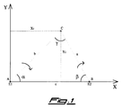
- the two transmitters E1, E2 and the receiver are the vertices A, B and C, respectively, of a triangle whose inner angles are ⁇ , ⁇ and ⁇ , respectively, and the sides opposite to said angles are a, b and c, respectively.
- the beam transmitted by E1 carries a continuously changing code indicating the value of the a angle, and similarly the beam transmitted by E2 carries the value of the ⁇ angle.
- the information transmitted are not the values of the ⁇ and ⁇ angles shown in fig.1, but the angle of emission with respect to an arbitrary reference direction from which the ⁇ and ⁇ angles are easily calculated.
- the vehicle operates, for example, in the area defined by vertex C being included between vertices A and B and above them ( ⁇ and ⁇ ⁇ 90°), taking the Y-axis, for example, as 0° the value transmitted by E1 is 90°- ⁇ and the value transmitted by E2 is 270°+ ⁇ . Therefore, it is clear that the information transmitted need not contain also the "name" of the source since the receiver knows that values ranging from 0° to 90° come from E1 and values ranging from 270° to 360° come from E2, according to the example above.
- the fixed distance between the transmitters i.e. the length of side c
- the base Since the base and the two angles ⁇ and ⁇ adjacent thereto are known, all the other elements of the triangle are easily obtained, as well as the receiver Cartesian coordinates X c , Y c in a frame of reference wherein A is in the origin and B on the X-axis.
- the base can be positioned in any way with respect to the operation area, even diagonally or in the middle thereof, and a same pair of transmitters can be used for the positioning of various vehicles operating in the different quadrants with respect to the base taken into consideration.
- the value code is transmitted by modulating the carrier wave of the electromagnetic transmission which is preferably a beam of laser light, but could also consist in microwaves or other types of waves, provided that they are sufficiently directive.
- the coding of the angle value is performed through a binary n-bits code by generating a sequence of 2 n binary configurations of n bits.
- the Applicant devised the method according to the present invention in which the sequence of the 2 n binary configurations of n bits is made up of codes successively "overlapping" for n-1 bits.
- the n bits of each of the 2 n configurations in the sequence are the n-1 last bits of the preceding configuration plus 1 more bit.
- the coding sequence instead of consisting in n*2 n bits read as 2 n codes of n bits each, is made up of 2 n +(n-1) bits only which are still read as 2 n codes of n bits but each code overlaps the following one for the first n-1 bits of the latter.
- the reading is performed by shifting along the sequence by 1 bit at a time instead of n bits at a time.
- no error check bits are needed because the additional bit transmitted (just 1 or 0) is used, in practice, as a "clock signal" to scan the coding sequence.
- the receiver automatically discards the values not compatible with the previously calculated position and the vehicle speed. Therefore, the frequency modulation required is 1/(n+n') of that required with independent configurations, i.e. just 0.5 MHz instead of 11.5 MHz, referring to the above-cited example. Since the cost and the delicacy of the laser modulators are proportional to the frequency they reach, it is clear that such a method allows a considerable saving and a significant increase in reliability. The following example will make the present method still clearer.
- each transmitter E1, E2 must modulate just 1 bit at a time (after the 1st reading) since the receiver uses the 2 preceding bits in the sequence to obtain the complete 3-bits code containing the binary value corresponding to the coded value.
- the transmitters and the receiver are provided with the same coding pattern, which is used by the modulator in the transmitters and by the demodulator in the receiver.
- a plurality of coding patterns may be provided corresponding to increasing values of n so as to use the most suitable angular resolution for each application of the present method.
- the modulating capacities of the relevant apparatus may be differently allocated according, for example, to the speed of the vehicle to be remotely controlled. While the control with a very high precision of slowly moving vehicles implies higher values of n and t (more precise but less frequent position calculation), the control of vehicles moving faster but not requiring great precision implies lower values of n and t (less precise but more frequent position calculation), yet maintaining in both instances the modulating frequency 2 n /t within the limits of the apparatus.
- E1 Since the directive beam emitted by E1, E2 has a finite width in the horizontal plane (e.g. 1 minute), it will sweep the receiver detector for a finite time during which, in general, a plurality of coded angular values will be transmitted thereto. Obviously, the actual value utilized in the position calculation will be the mean value.
- a tyred lifting truck moving pallets over an asphalted area of 100 x 100 meters requires a ⁇ 5 cm precision. Since the ground vibrational disturbances are very small, a fixed installation of the two transmitters allows for a high mechanical precision.
- the VTS is the portion of the apparatus actually embodying the method according to the present invention. As mentioned above, it includes a pair of transmitters E1, E2 emitting directive electromagnetic waves, preferably laser beams.
- the carrier wave is modulated by a modulator in order to contain a binary code produced by a coder as explained before.
- the transmitters are usually mounted on stands or the like at 2-3 m above the ground, and they rotate at a constant speed in a plane parallel to the surface on which the mobile vehicle operates.
- the laser modulator included in the transmitters may be of the double-exit type, i.e. the laser beam is simultaneously emitted in two opposite directions, for example the a and ⁇ +180° directions, by means of a mirror device. Since the transmitted value is a in both directions, the beam emitted along ⁇ +180° will be slightly modified so that the receiver can distinguish it and add 180° to its value for the correct calculation.
- the receiver is obviously mounted on top of the vehicle and includes a 360° detector so as to detect the transmissions from E1 and E2 regardless of the orientation of the vehicle.
- the detector may also be made up of a plurality of detectors (e.g. 4 detectors covering 90° each) electrically coupled to form a 360° detector.
- the receiver also includes a demodulator to demodulate the transmissions, a decoder to obtain the coded values from the binary values, and a processing unit to perform the triangulation.
- the position calculated by the VTS is transmitted to the DCS which includes a plurality of processing units and interfaces for performing the following functions:
- Each function is specifically controlled via software according to the operations to be performed.
- the operating software contains the intervention priorities for allocating the processing capacities of the DCS, so that a proper quick stopping and/or correcting action can be taken upon occurrence of any specific event.
- Typical examples of events requiring a quick intervention are another vehicle or a person crossing the path a short distance ahead of the vehicle, or a fixed underground obstacle (e.g. a root) blocking the vehicle.
- the DCS must therefore operate in real-time mode with "interrupt" features, and includes a plurality of sensors for gathering the data on pressure, temperature, speed, etc. required to perform the checks and controls, as well as TV cameras, image processors, infrared or proximity sensors and the like to recognize objects, edge posts, etc.
- the route to be followed by the vehicle is defined prior to the beginning of the work by putting together the perimeter of the operation area. This can be done either through conventional measuring by means of other separate instruments, or by having the vehicle, driven by an operator, travel along the perimeter with the VTS in "acquisition" mode. Once the perimeter has been acquired, the DCS calculates the trajectories according to the programmed operations to be performed.
- the DCS is connected through a serial line to the TCS, which is capable of transmitting and receiving messages to and from an operator.
- This link between the DCS and the TCS allows the former to transmit an alarm signal in case it is unable to cope with a particular situation.
- the operator can understand the nature of the problem and transmit the proper controls to resume the vehicle operations, or at least he can intervene to stop the vehicle if something goes wrong in the DCS.
- the TCS also allows the recording of all the data concerning the operations performed and the anomalies occurred. It is substantially made up of a pair of transceivers coupled to a modem, so as to transmit and receive digitalized messages, one of said transceivers making part of an operator-controlled ground station.
- the use of frequencies in the VHF, UHF and SHF bands allows for a range of some kilometers even with little power.
Landscapes
- Engineering & Computer Science (AREA)
- Physics & Mathematics (AREA)
- General Physics & Mathematics (AREA)
- Radar, Positioning & Navigation (AREA)
- Remote Sensing (AREA)
- Aviation & Aerospace Engineering (AREA)
- Automation & Control Theory (AREA)
- Electromagnetism (AREA)
- Control Of Position, Course, Altitude, Or Attitude Of Moving Bodies (AREA)
- Electric Propulsion And Braking For Vehicles (AREA)
- Control Of Position Or Direction (AREA)
- Selective Calling Equipment (AREA)
- Position Fixing By Use Of Radio Waves (AREA)
- Traffic Control Systems (AREA)
- Radar Systems Or Details Thereof (AREA)
- Apparatus Associated With Microorganisms And Enzymes (AREA)
- Sampling And Sample Adjustment (AREA)
- Pressure Vessels And Lids Thereof (AREA)
Claims (3)
- Verfahren zum Bestimmen der Position eines beweglichen Fahrzeuges, ausgerüstet mit einem Empfänger, mittels durch den Empfänger durchgeführter Triangulierung auf der Grundlage von Winkeldaten, welche erhalten werden durch Verarbeiten der modulierten direktiv-elektromagnetischen Signale, welche von zumindest zwei festgelegten sich drehenden Transmittern (E1, E2) emittiert werden, dadurch gekennzeichnet, daß das Verfahren die folgenden Betriebsschritte umfaßt:Aufteilen der 360° der Drehung in 2n-Winkelwerte, wobei n eine ganze Zahl ist;Erzeugen einer Kodierfolge von 2n-Binärkonfigurationen von n Bits, welche sukzessive um n-1 Bits überlappen, wodurch die n Bits von jeder der 2n-Konfigurationen in der Folge die n-1 letzten Bits der vorangegangenen Konfiguration sind, zuzüglich einem weiteren Bit, wobei die Kodierfolge oder -Sequenz gebildet ist aus 2n+(n-1) Bits;Erzeugen eines Kodiermusters, wobei die Winkelwerte kodiert werden durch sukzessives Zuordnen dieser jeweils einem der 2n-Binärwerte, entsprechend den sukzessiven 2n-Konfigurationen von n Bits, welche die Kodierfolge bilden;Speichern des Kodiermustes in den Transmittern (E1, E2) und in dem Empfänger;Beginnen der Rotationen der zwei Transmitter (E1, E2) bei einer konstanten Geschwindigkeit, wobei sie derart korreliert sind, daß es vermieden wird, daß der Empfänger gleichzeitig von beiden Direktivübertragungen überstrichen wird, welche von den zwei Transmittern emittiert werden;Übertragen der Winkeldaten entsprechend der Emissionsrichtung der Strahlen durch Bit-weises Lesen der Kodierfolge oder -Sequenz nach den ersten n Bits, wobei das Trägerwellensignal gemäß dem Lesen moduliert wird;Demodulieren der durch den Empfänger erfaßten Signale und Erhalten der kodierten Winkelwerte durch Addieren des letzten vom jeweiligen Transmitter (E1, E2) empfangenen Bits zu den n-1 letzten Bits, welche vorangehend von dem Transmitter empfangen wurden; undBerechnen der Fahrzeugposition mittels Triangulierung unter Verwendung der letzten Mittelwinkelwerte, erhalten aus den Signalen.
- Vorrichtung zur Fernsteuerung eines beweglichen Fahrzeuges, ausgerüstet mit einem Empfänger, und zur Bestimmung der Position eines Fahrzeuges mittels einer Triangulierung, durchgeführt durch den Empfänger auf der Grundlage der Winkeldaten, erhalten durch Verarbeitung der modulierten direktiv-elektromagnetischen Signale, welche von zumindest zwei festgelegten, sich drehenden Transmittern emittiert werden, wobei die Vorrichtung zumindest zwei feste oder festgelegte sich drehende Transmitter (E1, E2), welche modulierte direktiv-elektromagnetische Signale emittieren, und einen an dem Fahrzeug montierten Empfänger, welcher mit einem 360° Signaldetektor ausgerüstet ist, einen Demodulator und eine Verarbeitungseinheit enthält, dadurch gekennzeichnet, daß die Vorrichtung des weiteren aufweist eine Verarbeitungseinheit, welche zum Erzeugen eines Kodiermusters der Winkelwerte der Emission der Signale gemäß dem Verfahren von Anspruch 1 geeignet ist, eine Speichereinrichtung, welche einen Teil der Transmitter (E1, E2) und des Empfängers bildet und geeignet ist zum Rückhalten des Kodiermusters, eine Korrelationseinrichtung, geeignet zum Synchronisieren der Drehungen der zwei Transmitter (E1, E2), eine Verarbeitungseinheit in jedem Transmitter (E1, E2), geeignet zum Modulieren des Trägerwellensignales gemäß den Daten, welche in dem Kodiermuster enthalten sind, welches zurückgehalten oder gespeichert ist in der Speichereinrichtung, eine Vielzahl von Verarbeitungseinheiten und Schnittstellen, montiert an dem Fahrzeug und geeignet zum Durchführen der Antriebs- und Steuerfunktionen davon, wie auch ein Transceiver-oder Empfänger/Sender-Kommunikationssystem, verbunden mit dem Antriebs- und Steuersystem und gebildet aus einem ersten Transceiver, welcher mit einem Modem an dem Fahrzeug gekoppelt ist, und einem zweiten Transceiver, welcher mit einem Modem gekoppelt ist und einen Teil der benutzergesteuerten Bodenstation bildet, aufweist.
- Vorrichtung nach Anspruch 2, dadurch gekennzeichnet, daß Laserstrahlen als direktiv-elektromagnetische Signale verwendet werden , und daß die Lasermodulatoren, die in den Transmittern (E1, E2) enthalten sind, von dem Doppelausgangstyp sind, wodurch der Laserstrahl gleichzeitig in zwei entgegengesetzten Richtungen emittiert wird, wobei der in der einen Richtung emittierte Strahl leicht modifiziert ist, so daß der Empfänger ihn von dem anderen Strahl unterscheiden kann.
Applications Claiming Priority (3)
| Application Number | Priority Date | Filing Date | Title |
|---|---|---|---|
| IT93PV000005A ITPV930005A1 (it) | 1993-05-25 | 1993-05-25 | Sistema "arianna" |
| ITPV930005 | 1993-05-25 | ||
| PCT/IT1994/000067 WO1994028436A1 (en) | 1993-05-25 | 1994-05-24 | Method for determining the precise position of a mobile vehicle moving in an open space and apparatus employing said method for the vehicle remote control |
Publications (2)
| Publication Number | Publication Date |
|---|---|
| EP0701701A1 EP0701701A1 (de) | 1996-03-20 |
| EP0701701B1 true EP0701701B1 (de) | 1998-01-14 |
Family
ID=11397292
Family Applications (1)
| Application Number | Title | Priority Date | Filing Date |
|---|---|---|---|
| EP94918507A Expired - Lifetime EP0701701B1 (de) | 1993-05-25 | 1994-05-24 | Verfahren zur bestimmung der genauen position eines frei beweglichen mobilen fahrzeuges und gerat zur anwendung dieses verfahrens fur die fahrzeugfernsteuerung |
Country Status (11)
| Country | Link |
|---|---|
| US (1) | US5715042A (de) |
| EP (1) | EP0701701B1 (de) |
| JP (1) | JPH08510552A (de) |
| AT (1) | ATE162313T1 (de) |
| CA (1) | CA2163440A1 (de) |
| DE (1) | DE69407967T2 (de) |
| DK (1) | DK0701701T3 (de) |
| ES (1) | ES2112548T3 (de) |
| GR (1) | GR3025906T3 (de) |
| IT (1) | ITPV930005A1 (de) |
| WO (1) | WO1994028436A1 (de) |
Families Citing this family (17)
| Publication number | Priority date | Publication date | Assignee | Title |
|---|---|---|---|---|
| ATE274719T1 (de) * | 1999-06-28 | 2004-09-15 | Siemens Ag | Verfahren und vorrichtung zur erfassung der bewegungsrichtung eines mobilen datenspeichers insbesondere bei einem identifikationssystem |
| US6853445B2 (en) * | 2002-01-07 | 2005-02-08 | Motorola, Inc. | Two-dimensional angle of arrival detection device |
| KR100520078B1 (ko) | 2003-08-04 | 2005-10-12 | 삼성전자주식회사 | 로봇시스템 및 비콘 |
| US7015859B2 (en) * | 2003-11-14 | 2006-03-21 | General Electric Company | Electromagnetic tracking system and method using a three-coil wireless transmitter |
| EP1815267B1 (de) | 2004-11-15 | 2015-06-10 | Nanotron Technologies GmbH | Symmetrisches mehrwegverfahren zur bestimmung des abstandes zweier senderempfänger |
| US7256736B2 (en) * | 2005-08-11 | 2007-08-14 | International Business Machines Corporation | Location system with swept digital beacon |
| DE202005017113U1 (de) * | 2005-10-28 | 2006-03-30 | Leibniz-Institut für Agrartechnik Bornim e.V. | Vorrichtung zur Erfassung und Online-Übertragung von Bewegungsdaten empfindlicher Güter in logistischen Prozessen |
| US20070167744A1 (en) * | 2005-11-23 | 2007-07-19 | General Electric Company | System and method for surgical navigation cross-reference to related applications |
| US7471202B2 (en) | 2006-03-29 | 2008-12-30 | General Electric Co. | Conformal coil array for a medical tracking system |
| US7532997B2 (en) | 2006-04-17 | 2009-05-12 | General Electric Company | Electromagnetic tracking using a discretized numerical field model |
| US20080154120A1 (en) * | 2006-12-22 | 2008-06-26 | General Electric Company | Systems and methods for intraoperative measurements on navigated placements of implants |
| US20080177203A1 (en) * | 2006-12-22 | 2008-07-24 | General Electric Company | Surgical navigation planning system and method for placement of percutaneous instrumentation and implants |
| US8873026B2 (en) * | 2011-08-05 | 2014-10-28 | Qualcomm Incorporated | Proximity sensor distance detection ambiguity removal |
| US9788481B2 (en) * | 2014-10-28 | 2017-10-17 | Deere & Company | Robotic mower navigation system |
| DE102019002516B4 (de) * | 2019-04-07 | 2025-01-30 | Androtec Gmbh | Messanordnung und Verfahren zur optischen oder quasioptischen Positionsbestimmung |
| US11069142B2 (en) * | 2019-05-31 | 2021-07-20 | Wormhole Labs, Inc. | Using live feeds to produce 1st person, spatial, and real life views |
| US11496989B2 (en) | 2020-03-03 | 2022-11-08 | Daegu Gyeongbuk Institute Of Science And Technology | Positioning network system, apparatus and method using a mobile object |
Family Cites Families (6)
| Publication number | Priority date | Publication date | Assignee | Title |
|---|---|---|---|---|
| US3818478A (en) * | 1972-08-14 | 1974-06-18 | Raytheon Co | Coded navigation system |
| US4007991A (en) * | 1973-07-02 | 1977-02-15 | Saab-Scania Aktiebolag | System for transmitting position information |
| US4564841A (en) * | 1981-01-15 | 1986-01-14 | Neidell Norman S | Navigational systems using phase encoded angular coordinates |
| DE3107674A1 (de) * | 1981-02-28 | 1982-09-16 | M.A.N. Maschinenfabrik Augsburg-Nürnberg AG, 8000 München | Verfahren zur bewegungssteuerung mit laserstrahlen |
| GB2152320A (en) * | 1983-12-07 | 1985-07-31 | Robert James Siddall | Position location system |
| DE3526564A1 (de) * | 1985-07-25 | 1987-02-05 | Krupp Gmbh | Containerumschlaganlage |
-
1993
- 1993-05-25 IT IT93PV000005A patent/ITPV930005A1/it not_active Application Discontinuation
-
1994
- 1994-05-24 EP EP94918507A patent/EP0701701B1/de not_active Expired - Lifetime
- 1994-05-24 JP JP7500461A patent/JPH08510552A/ja active Pending
- 1994-05-24 WO PCT/IT1994/000067 patent/WO1994028436A1/en not_active Ceased
- 1994-05-24 DK DK94918507.8T patent/DK0701701T3/da active
- 1994-05-24 CA CA002163440A patent/CA2163440A1/en not_active Abandoned
- 1994-05-24 AT AT94918507T patent/ATE162313T1/de not_active IP Right Cessation
- 1994-05-24 US US08/549,855 patent/US5715042A/en not_active Expired - Fee Related
- 1994-05-24 DE DE69407967T patent/DE69407967T2/de not_active Expired - Fee Related
- 1994-05-24 ES ES94918507T patent/ES2112548T3/es not_active Expired - Lifetime
-
1998
- 1998-01-15 GR GR970402937T patent/GR3025906T3/el unknown
Also Published As
| Publication number | Publication date |
|---|---|
| ATE162313T1 (de) | 1998-01-15 |
| GR3025906T3 (en) | 1998-04-30 |
| JPH08510552A (ja) | 1996-11-05 |
| DE69407967D1 (de) | 1998-02-19 |
| ITPV930005A1 (it) | 1994-11-25 |
| CA2163440A1 (en) | 1994-12-08 |
| US5715042A (en) | 1998-02-03 |
| WO1994028436A1 (en) | 1994-12-08 |
| DE69407967T2 (de) | 1998-07-30 |
| ES2112548T3 (es) | 1998-04-01 |
| ITPV930005A0 (it) | 1993-05-25 |
| EP0701701A1 (de) | 1996-03-20 |
| DK0701701T3 (da) | 1998-02-09 |
Similar Documents
| Publication | Publication Date | Title |
|---|---|---|
| EP0701701B1 (de) | Verfahren zur bestimmung der genauen position eines frei beweglichen mobilen fahrzeuges und gerat zur anwendung dieses verfahrens fur die fahrzeugfernsteuerung | |
| EP0936519B1 (de) | Integriertes Fahrzeugpositionier- und -navigationssystem, dessen Vorrichtung und Verfahren | |
| US4647784A (en) | Vehicle guidance and control system | |
| EP0341890B1 (de) | Automatische Fahrzeugsteuerung | |
| US20050104736A1 (en) | Work site tracking system and method | |
| EP3913328A1 (de) | Fahrzeugpositionierungsvorrichtung, -system und -verfahren und fahrzeug | |
| DE102013104239B3 (de) | Laserscanner für die Navigation eines Fahrzeugs | |
| US5117301A (en) | System for transmitting information to moving object | |
| US9689963B2 (en) | Navigation system and method | |
| EP1505465B1 (de) | Einrichtung zur Ortung eines Roboters | |
| EP0522829A2 (de) | Steuerungs- und Überwachungssystem für bewegte Körper | |
| US4939522A (en) | Method and system for monitoring vehicle location | |
| US3046681A (en) | Control apparatus | |
| JPH09120313A (ja) | 作業車の誘導制御装置 | |
| EP0363072A1 (de) | Automatisierte Fahrzeugsteuerung | |
| DE4409760A1 (de) | Multifunktionsgerät für fahrerlose Transportfahrzeuge | |
| JPS58102177A (ja) | 移動物体の現在位置および方位測定装置 | |
| JPH05250033A (ja) | 自動誘導システム | |
| JP3390545B2 (ja) | 移動体からの画像伝送方法 | |
| EP0636902B1 (de) | Verfahren zum Bestimmen des Ortes eines sich bewegenden Fahrzeuges in einem begrenzten Raum und Vorrichtung zur Durchführung dieses Verfahrens | |
| US20220159897A1 (en) | Safe autonomous agricultural machine | |
| JPS5916017A (ja) | 移動体の無人移動システム | |
| JP2941103B2 (ja) | 移動体の位置検知装置 | |
| Finlay et al. | Pattern Recognition Techniques for Long-range Vehicle Position Tracking | |
| WO2004021072A2 (en) | Electro-optic platform |
Legal Events
| Date | Code | Title | Description |
|---|---|---|---|
| PUAI | Public reference made under article 153(3) epc to a published international application that has entered the european phase |
Free format text: ORIGINAL CODE: 0009012 |
|
| 17P | Request for examination filed |
Effective date: 19951205 |
|
| AK | Designated contracting states |
Kind code of ref document: A1 Designated state(s): AT BE CH DE DK ES FR GB GR IE IT LI LU NL PT SE |
|
| 17Q | First examination report despatched |
Effective date: 19960604 |
|
| GRAG | Despatch of communication of intention to grant |
Free format text: ORIGINAL CODE: EPIDOS AGRA |
|
| GRAG | Despatch of communication of intention to grant |
Free format text: ORIGINAL CODE: EPIDOS AGRA |
|
| GRAH | Despatch of communication of intention to grant a patent |
Free format text: ORIGINAL CODE: EPIDOS IGRA |
|
| GRAH | Despatch of communication of intention to grant a patent |
Free format text: ORIGINAL CODE: EPIDOS IGRA |
|
| GRAA | (expected) grant |
Free format text: ORIGINAL CODE: 0009210 |
|
| AK | Designated contracting states |
Kind code of ref document: B1 Designated state(s): AT BE CH DE DK ES FR GB GR IE IT LI LU NL PT SE |
|
| REF | Corresponds to: |
Ref document number: 162313 Country of ref document: AT Date of ref document: 19980115 Kind code of ref document: T |
|
| REG | Reference to a national code |
Ref country code: CH Ref legal event code: NV Representative=s name: ABATRON-PATENTBUERO AG Ref country code: CH Ref legal event code: EP |
|
| REG | Reference to a national code |
Ref country code: DK Ref legal event code: T3 |
|
| REF | Corresponds to: |
Ref document number: 69407967 Country of ref document: DE Date of ref document: 19980219 |
|
| ET | Fr: translation filed | ||
| ITF | It: translation for a ep patent filed | ||
| REG | Reference to a national code |
Ref country code: ES Ref legal event code: FG2A Ref document number: 2112548 Country of ref document: ES Kind code of ref document: T3 |
|
| PGFP | Annual fee paid to national office [announced via postgrant information from national office to epo] |
Ref country code: FR Payment date: 19980520 Year of fee payment: 5 |
|
| REG | Reference to a national code |
Ref country code: IE Ref legal event code: FG4D Free format text: 78406 |
|
| REG | Reference to a national code |
Ref country code: PT Ref legal event code: SC4A Free format text: AVAILABILITY OF NATIONAL TRANSLATION Effective date: 19980408 |
|
| PLBE | No opposition filed within time limit |
Free format text: ORIGINAL CODE: 0009261 |
|
| STAA | Information on the status of an ep patent application or granted ep patent |
Free format text: STATUS: NO OPPOSITION FILED WITHIN TIME LIMIT |
|
| 26N | No opposition filed | ||
| PGFP | Annual fee paid to national office [announced via postgrant information from national office to epo] |
Ref country code: SE Payment date: 19991130 Year of fee payment: 6 Ref country code: CH Payment date: 19991130 Year of fee payment: 6 |
|
| PGFP | Annual fee paid to national office [announced via postgrant information from national office to epo] |
Ref country code: LU Payment date: 19991201 Year of fee payment: 6 |
|
| PGFP | Annual fee paid to national office [announced via postgrant information from national office to epo] |
Ref country code: PT Payment date: 19991217 Year of fee payment: 7 |
|
| PG25 | Lapsed in a contracting state [announced via postgrant information from national office to epo] |
Ref country code: FR Free format text: LAPSE BECAUSE OF NON-PAYMENT OF DUE FEES Effective date: 20000131 |
|
| REG | Reference to a national code |
Ref country code: FR Ref legal event code: ST |
|
| REG | Reference to a national code |
Ref country code: PT Ref legal event code: NF4A Free format text: 'RESTITUTIO IN INTEGRUM' Effective date: 19991217 |
|
| PG25 | Lapsed in a contracting state [announced via postgrant information from national office to epo] |
Ref country code: LU Free format text: LAPSE BECAUSE OF NON-PAYMENT OF DUE FEES Effective date: 20000524 |
|
| PG25 | Lapsed in a contracting state [announced via postgrant information from national office to epo] |
Ref country code: SE Free format text: LAPSE BECAUSE OF NON-PAYMENT OF DUE FEES Effective date: 20000525 |
|
| PG25 | Lapsed in a contracting state [announced via postgrant information from national office to epo] |
Ref country code: LI Free format text: LAPSE BECAUSE OF NON-PAYMENT OF DUE FEES Effective date: 20000531 Ref country code: CH Free format text: LAPSE BECAUSE OF NON-PAYMENT OF DUE FEES Effective date: 20000531 |
|
| PGFP | Annual fee paid to national office [announced via postgrant information from national office to epo] |
Ref country code: IE Payment date: 20001127 Year of fee payment: 7 Ref country code: GR Payment date: 20001127 Year of fee payment: 7 |
|
| PGFP | Annual fee paid to national office [announced via postgrant information from national office to epo] |
Ref country code: AT Payment date: 20001128 Year of fee payment: 7 |
|
| PGFP | Annual fee paid to national office [announced via postgrant information from national office to epo] |
Ref country code: DK Payment date: 20001129 Year of fee payment: 7 |
|
| PGFP | Annual fee paid to national office [announced via postgrant information from national office to epo] |
Ref country code: NL Payment date: 20001130 Year of fee payment: 7 Ref country code: BE Payment date: 20001130 Year of fee payment: 7 |
|
| REG | Reference to a national code |
Ref country code: CH Ref legal event code: PL |
|
| GBPC | Gb: european patent ceased through non-payment of renewal fee |
Effective date: 20000524 |
|
| EUG | Se: european patent has lapsed |
Ref document number: 94918507.8 |
|
| REG | Reference to a national code |
Ref country code: GB Ref legal event code: 728V |
|
| PGFP | Annual fee paid to national office [announced via postgrant information from national office to epo] |
Ref country code: GB Payment date: 20010504 Year of fee payment: 8 |
|
| PG25 | Lapsed in a contracting state [announced via postgrant information from national office to epo] |
Ref country code: IE Free format text: LAPSE BECAUSE OF NON-PAYMENT OF DUE FEES Effective date: 20010524 Ref country code: AT Free format text: LAPSE BECAUSE OF NON-PAYMENT OF DUE FEES Effective date: 20010524 |
|
| PG25 | Lapsed in a contracting state [announced via postgrant information from national office to epo] |
Ref country code: GR Free format text: LAPSE BECAUSE OF NON-PAYMENT OF DUE FEES Effective date: 20010531 Ref country code: DK Free format text: LAPSE BECAUSE OF NON-PAYMENT OF DUE FEES Effective date: 20010531 Ref country code: BE Free format text: LAPSE BECAUSE OF NON-PAYMENT OF DUE FEES Effective date: 20010531 |
|
| REG | Reference to a national code |
Ref country code: GB Ref legal event code: 728Y |
|
| BERE | Be: lapsed |
Owner name: MILANI CARLO Effective date: 20010531 |
|
| PG25 | Lapsed in a contracting state [announced via postgrant information from national office to epo] |
Ref country code: PT Free format text: LAPSE BECAUSE OF NON-PAYMENT OF DUE FEES Effective date: 20011130 |
|
| PG25 | Lapsed in a contracting state [announced via postgrant information from national office to epo] |
Ref country code: NL Free format text: LAPSE BECAUSE OF NON-PAYMENT OF DUE FEES Effective date: 20011201 |
|
| PGFP | Annual fee paid to national office [announced via postgrant information from national office to epo] |
Ref country code: ES Payment date: 20011224 Year of fee payment: 8 |
|
| REG | Reference to a national code |
Ref country code: GB Ref legal event code: IF02 |
|
| REG | Reference to a national code |
Ref country code: DK Ref legal event code: EBP |
|
| NLV4 | Nl: lapsed or anulled due to non-payment of the annual fee |
Effective date: 20011201 |
|
| PGFP | Annual fee paid to national office [announced via postgrant information from national office to epo] |
Ref country code: DE Payment date: 20020228 Year of fee payment: 8 |
|
| REG | Reference to a national code |
Ref country code: IE Ref legal event code: MM4A |
|
| REG | Reference to a national code |
Ref country code: PT Ref legal event code: MM4A Free format text: LAPSE DUE TO NON-PAYMENT OF FEES Effective date: 20011130 |
|
| PG25 | Lapsed in a contracting state [announced via postgrant information from national office to epo] |
Ref country code: GB Free format text: LAPSE BECAUSE OF NON-PAYMENT OF DUE FEES Effective date: 20020524 |
|
| PG25 | Lapsed in a contracting state [announced via postgrant information from national office to epo] |
Ref country code: ES Free format text: LAPSE BECAUSE OF NON-PAYMENT OF DUE FEES Effective date: 20020525 |
|
| PG25 | Lapsed in a contracting state [announced via postgrant information from national office to epo] |
Ref country code: DE Free format text: LAPSE BECAUSE OF NON-PAYMENT OF DUE FEES Effective date: 20021203 |
|
| GBPC | Gb: european patent ceased through non-payment of renewal fee |
Effective date: 20020524 |
|
| REG | Reference to a national code |
Ref country code: ES Ref legal event code: FD2A Effective date: 20030611 |
|
| PG25 | Lapsed in a contracting state [announced via postgrant information from national office to epo] |
Ref country code: IT Free format text: LAPSE BECAUSE OF NON-PAYMENT OF DUE FEES Effective date: 20050524 |