EP0700526B1 - Systeme de navigation et de poursuite pour des espaces blindes - Google Patents
Systeme de navigation et de poursuite pour des espaces blindes Download PDFInfo
- Publication number
- EP0700526B1 EP0700526B1 EP94916305A EP94916305A EP0700526B1 EP 0700526 B1 EP0700526 B1 EP 0700526B1 EP 94916305 A EP94916305 A EP 94916305A EP 94916305 A EP94916305 A EP 94916305A EP 0700526 B1 EP0700526 B1 EP 0700526B1
- Authority
- EP
- European Patent Office
- Prior art keywords
- signals
- base station
- roving receiver
- signal
- roving
- Prior art date
- Legal status (The legal status is an assumption and is not a legal conclusion. Google has not performed a legal analysis and makes no representation as to the accuracy of the status listed.)
- Expired - Lifetime
Links
- 230000005540 biological transmission Effects 0.000 claims abstract description 35
- 241001061260 Emmelichthys struhsakeri Species 0.000 claims description 52
- 230000001902 propagating effect Effects 0.000 claims description 6
- 238000005314 correlation function Methods 0.000 claims description 2
- 230000001934 delay Effects 0.000 claims description 2
- 238000005259 measurement Methods 0.000 description 7
- 230000000644 propagated effect Effects 0.000 description 5
- 238000004364 calculation method Methods 0.000 description 4
- 238000010586 diagram Methods 0.000 description 3
- 230000007704 transition Effects 0.000 description 3
- 230000010354 integration Effects 0.000 description 2
- 101100350613 Arabidopsis thaliana PLL1 gene Proteins 0.000 description 1
- 101100082028 Arabidopsis thaliana PLL2 gene Proteins 0.000 description 1
- 238000012935 Averaging Methods 0.000 description 1
- 238000004590 computer program Methods 0.000 description 1
- 238000010276 construction Methods 0.000 description 1
- 239000013078 crystal Substances 0.000 description 1
- 238000000034 method Methods 0.000 description 1
- 238000012544 monitoring process Methods 0.000 description 1
- 230000005855 radiation Effects 0.000 description 1
- 238000011084 recovery Methods 0.000 description 1
- 230000008054 signal transmission Effects 0.000 description 1
Images


Classifications
-
- G—PHYSICS
- G01—MEASURING; TESTING
- G01S—RADIO DIRECTION-FINDING; RADIO NAVIGATION; DETERMINING DISTANCE OR VELOCITY BY USE OF RADIO WAVES; LOCATING OR PRESENCE-DETECTING BY USE OF THE REFLECTION OR RERADIATION OF RADIO WAVES; ANALOGOUS ARRANGEMENTS USING OTHER WAVES
- G01S5/00—Position-fixing by co-ordinating two or more direction or position line determinations; Position-fixing by co-ordinating two or more distance determinations
- G01S5/02—Position-fixing by co-ordinating two or more direction or position line determinations; Position-fixing by co-ordinating two or more distance determinations using radio waves
- G01S5/10—Position of receiver fixed by co-ordinating a plurality of position lines defined by path-difference measurements, e.g. omega or decca systems
-
- G—PHYSICS
- G01—MEASURING; TESTING
- G01S—RADIO DIRECTION-FINDING; RADIO NAVIGATION; DETERMINING DISTANCE OR VELOCITY BY USE OF RADIO WAVES; LOCATING OR PRESENCE-DETECTING BY USE OF THE REFLECTION OR RERADIATION OF RADIO WAVES; ANALOGOUS ARRANGEMENTS USING OTHER WAVES
- G01S5/00—Position-fixing by co-ordinating two or more direction or position line determinations; Position-fixing by co-ordinating two or more distance determinations
- G01S5/0009—Transmission of position information to remote stations
Definitions
- the invention relates to a navigation and tracking system which can be used in shielded spaces.
- EP-B-0 303 371 describes a navigation and tracking system (CURSORTM) in which the signals from several independent point signal sources (eg. radio transmitters) are received at two locations, one being at a fixed and known location (the "base station"), and the other being attached to the roving object whose position is to be determined (the "rover").
- a representation of the signals received at one of the locations, A is sent by any convenient means (e.g., a narrow-band radio link) to the other, B, where the said representation is used in a computer program to calculate the position of the rover, together with a similar representation derived from the same signal sources at B.
- CURSORTM navigation and tracking system
- the transmission signals may be modulated and timing delays between the respective signals may be determined in order to enable the relative location of the roving receiver to be determined, in which case the substitute signals may replicas of the transmitted signals, the system including means for comparing the signals received by the base station and roving receiver, which includes means for correlating the signals to produce estimates of the cross-correlation function to determine the time delay between the signals.
- FIG. 2a depicts normal operation where the signals from a signal source, Tx, at vector position a , are received by the base station B at the origin of coordinates, and by the rover R at vector position r . If N such signal sources are being used, then N independent measurements of the phase difference, ⁇ , between base and rover are made, such that where the subscript i denotes the channel number (1 to N), ⁇ i the angular frequency of the signals, and c the speed of the waves.
- the geometry of operation inside the tunnel T is shown in Figure 2b.
- the rover R picks up the signals generated by the curvilinear structure F at distance l inside the tunnel, and hence the phase difference measured between base station B and rover R becomes where c' is the wave speed on the curvilinear structure F. If the exit to the tunnel and hence the position of Q are considered to be at position
- d 2 and
- a 2 , then the phase difference measured on the signals from source Tx2 inside the tunnel T is where L is the total length of the curvilinear structure F'. As has already been mentioned, F and F' could be the same physical entity.
- the AM signals received directly from the transmitters on these two channels quickly fade out as the rover enters the tunnel, but are replaced by substitute sinusoids of the same frequency.
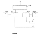
- These substitute signals are generated by equipment C (see Figure 7) at the entrance of the tunnel and are locked in phase with the respective carrier waves received directly. Their constant phase offsets are adjusted to match the directly-received signals at the entrance, thus ensuring a smooth transition into the tunnel.
- the substitute signal on channel 1 is propagated down the same leaky cable used for channels 3-8 in the direction from entrance to exit.
- the substitute signal on channel 2 is first conveyed to the far end of the tunnel by a fully screened cable K where it is then injected into the leaky cable F so that it propagates in the opposite direction to that of the signal on channel 1.
- the third measurement must have a different time delay from the other two and can be obtained from signals sent at a third frequency along another curvilinear structure, G 2 , set at as large an angle as possible with respect to G 1 (preferably 90°).
- the signal received from G 2 at J is then where c and d correspond to the values of ⁇ for the two ends of G 2 .
Landscapes
- Physics & Mathematics (AREA)
- Engineering & Computer Science (AREA)
- General Physics & Mathematics (AREA)
- Radar, Positioning & Navigation (AREA)
- Remote Sensing (AREA)
- Position Fixing By Use Of Radio Waves (AREA)
- Mobile Radio Communication Systems (AREA)
- Radar Systems Or Details Thereof (AREA)
- Burglar Alarm Systems (AREA)
Claims (9)
- Appareil destiné à être utilisé avec un système de navigation et/ou de poursuite ayant une station de base (B) et un récepteur mobile (R), tous deux capables de recevoir des signaux de plusieurs sources de transmission (Tx1, Tx2) et entre lesquels un signal de liaison (W) passe pour permettre la localisation relative du récepteur mobile, l'appareil permettant la détermination de la position du récepteur mobile (R) dans un espace (T) protégé contre la réception directe de signaux des sources de transmission (Tx1, Tx2) et étant caractérisé par :
un dispositif (P, Q, S) destiné à produire des signaux de substitution, chaque signal étant verrouillé en phase sur un signal d'une source respective de transmission (Tx1, Tx2) ou une réplique d'un tel signal, un ou plusieurs éléments curvilignes de transmission (F, F', F") s'étendant dans l'espace protégé (T) pour la création de champs dans l'espace protégé, un dispositif (P, Q, S) destiné à propager au moins deux des signaux de substitution en sens opposés le long de l'élément ou des éléments curvilignes de transmission (F, F', F") afin qu'ils soient reçus par le récepteur mobile (R), et un dispositif (S) destiné à transmettre le signal de liaison (W) entre deux récepteurs mobiles (R) et la station de base (B). - Appareil selon la revendication 1, dans lequel le dispositif (S) destiné à transmettre le signal de liaison (W) entre le récepteur mobile (R) et la station de base (B) comprend le dispositif destiné à recevoir les signaux du mobile dans l'espace protégé (T).
- Système de navigation et de poursuite ayant une station de base (B) et un récepteur mobile (R) tous deux capables de recevoir des signaux de plusieurs sources de transmission (Tx1, Tx2) et entre lesquels passe un signal de liaison (W) destiné à permettre une localisation relative du récepteur mobile (R), et comprenant un appareil selon la revendication 1 ou 2.
- Système de navigation et de poursuite selon la revendication 3, dans lequel les signaux de transmission sont modulés et des retards de synchronisation entre les signaux respectifs sont déterminés pour permettre la localisation relative du récepteur mobile (R).
- Système de navigation et de poursuite selon la revendication 4, dans lequel les signaux de substitution sont des répliques des signaux émis, et le système comprend un dispositif de comparaison des signaux reçus par la station de base (B) et le récepteur mobile (R), qui comporte un dispositif de corrélation des signaux pour la production d'estimations de la fonction de corrélation mutuelle et pour la détermination du retard temporel entre les signaux.
- Système selon la revendication 3, dans lequel les signaux de transmission sont modulés et le déphasage est déterminé.
- Système de navigation et de poursuite destiné à la localisation dans un espace électromagnétiquement protégé (T), l'appareil possédant une station de base (B) et un récepteur mobile (R), tous deux recevant des signaux de plusieurs générateurs de signaux, et entre lesquels passe un signal de liaison (W) destiné à permettre la localisation relative du récepteur mobile, un ou plusieurs éléments curvilignes de transmission (F, F', F") s'étendant dans l'espace protégé (T) pour la création de champs dans l'espace protégé, un dispositif (P, Q, S) pour la propagation des signaux créés en sens opposés le long de l'élément ou des éléments curvilignes de transmission (F, F', F") pour la réception par le récepteur mobile (R), et un dispositif (S) destiné à transmettre le signal de liaison (W) représentatif des signaux reçus par le mobile ou la station de base (B) entre le récepteur mobile et la station de base, et un dispositif (P, Q, S) destiné à comparer les représentations des signaux reçus par la liaison aux signaux directement reçus pour déterminer l'emplacement du mobile.
- Système selon la revendication 7, dans lequel le dispositif (S) destiné à transmettre le signal de liaison (W) entre le récepteur mobile (R) et la station de base (B) comporte un dispositif (S) destiné à recevoir des signaux du mobile dans l'espace protégé (T).
- Système selon l'une quelconque des revendications 3 à 8, comprenant en outre plusieurs récepteurs mobiles (R).
Applications Claiming Priority (3)
| Application Number | Priority Date | Filing Date | Title |
|---|---|---|---|
| GB9310976 | 1993-05-27 | ||
| GB939310976A GB9310976D0 (en) | 1993-05-27 | 1993-05-27 | Navigation and tracking system for shielded spaces |
| PCT/GB1994/001145 WO1994028432A1 (fr) | 1993-05-27 | 1994-05-26 | Systeme de navigation et de poursuite pour des espaces blindes |
Publications (2)
| Publication Number | Publication Date |
|---|---|
| EP0700526A1 EP0700526A1 (fr) | 1996-03-13 |
| EP0700526B1 true EP0700526B1 (fr) | 1999-07-14 |
Family
ID=10736236
Family Applications (1)
| Application Number | Title | Priority Date | Filing Date |
|---|---|---|---|
| EP94916305A Expired - Lifetime EP0700526B1 (fr) | 1993-05-27 | 1994-05-26 | Systeme de navigation et de poursuite pour des espaces blindes |
Country Status (8)
| Country | Link |
|---|---|
| US (1) | US5838279A (fr) |
| EP (1) | EP0700526B1 (fr) |
| AT (1) | ATE182219T1 (fr) |
| AU (1) | AU6801194A (fr) |
| DE (1) | DE69419511T2 (fr) |
| ES (1) | ES2133562T3 (fr) |
| GB (1) | GB9310976D0 (fr) |
| WO (1) | WO1994028432A1 (fr) |
Families Citing this family (24)
| Publication number | Priority date | Publication date | Assignee | Title |
|---|---|---|---|---|
| WO1995000821A1 (fr) * | 1993-06-25 | 1995-01-05 | Omniplex, Inc. | Determination de la position a l'aide d'emissions de sites cellulaires a synchronisation temporelle |
| GB9519087D0 (en) | 1995-09-19 | 1995-11-22 | Cursor Positioning Sys Ltd | Navigation and tracking system |
| GB9722324D0 (en) | 1997-10-22 | 1997-12-17 | Cambridge Positioning Sys Ltd | Positioning system for digital telephone networks |
| AUPP375498A0 (en) | 1998-05-29 | 1998-06-18 | Small, David | A method for creating a network positioning system (NPS) |
| GB9912724D0 (en) | 1999-06-01 | 1999-08-04 | Cambridge Positioning Sys Ltd | Radio positioning system |
| US7024331B2 (en) * | 2000-11-15 | 2006-04-04 | Scientific Generics Limited | Tag tracking |
| US7228228B2 (en) * | 2000-11-15 | 2007-06-05 | Sagentia Limited | Tag tracking |
| EP1255122A1 (fr) * | 2001-05-04 | 2002-11-06 | Cambridge Positioning Systems Limited | Unité de mesure pour sytème de radiolocalisation |
| EP1278074A1 (fr) | 2001-07-17 | 2003-01-22 | Cambridge Positioning Systems Limited | Système de positionement par radio |
| US6669125B1 (en) * | 2001-08-22 | 2003-12-30 | Dynacorp Engineering Inc. | Solids reduction processor |
| EP1376150B1 (fr) * | 2002-06-17 | 2009-11-11 | Cambridge Positioning Systems Limited | Système de radiolocalisation avec suppression d'interférence |
| ATE401579T1 (de) * | 2004-01-26 | 2008-08-15 | Cambridge Positioning Sys Ltd | Transfer kalibrierter zeitinformationen in einem mobilen endgerät |
| US7283091B1 (en) | 2005-08-08 | 2007-10-16 | Trimble Navigation Limited | Radio positioning system for providing position and time for assisting GPS signal acquisition in mobile unit |
| US7295156B2 (en) * | 2005-08-08 | 2007-11-13 | Trimble Navigation Limited | Cellphone GPS positioning system |
| WO2008073347A1 (fr) * | 2006-12-07 | 2008-06-19 | Venture Ad Astra, Llc | Système et procédé d'étalonnage dans l'espace temps |
| US8421675B2 (en) * | 2006-12-07 | 2013-04-16 | Digimarc Corporation | Systems and methods for locating a mobile device within a cellular system |
| US8451763B2 (en) * | 2006-12-07 | 2013-05-28 | Digimarc Corporation | Wireless local area network-based position locating systems and methods |
| CN101441262B (zh) * | 2007-11-20 | 2011-11-30 | 锐迪科微电子(上海)有限公司 | 立体交通导航方法和装置 |
| US8120527B2 (en) * | 2008-01-30 | 2012-02-21 | Javad Gnss, Inc. | Satellite differential positioning receiver using multiple base-rover antennas |
| US7983185B2 (en) * | 2009-02-12 | 2011-07-19 | Zulutime, Llc | Systems and methods for space-time determinations with reduced network traffic |
| US8463290B2 (en) | 2010-07-09 | 2013-06-11 | Digimarc Corporation | Mobile device positioning in dynamic groupings of communication devices |
| DE102011107164B4 (de) | 2011-07-13 | 2023-11-30 | Symeo Gmbh | Verfahren und System zur Ortung einer momentanen Position oder eines Einkoppelorts einer mobilen Einheit mittels Leckwellenleiters |
| US9282471B2 (en) | 2012-03-21 | 2016-03-08 | Digimarc Corporation | Positioning systems for wireless networks |
| JP6597651B2 (ja) * | 2017-01-18 | 2019-10-30 | 株式会社デンソー | 携帯端末検出装置、携帯端末検出方法 |
Family Cites Families (6)
| Publication number | Priority date | Publication date | Assignee | Title |
|---|---|---|---|---|
| DE2810691A1 (de) * | 1978-03-11 | 1979-09-13 | Licentia Gmbh | Nachrichtenuebertragungssystem |
| JPH0789676B2 (ja) * | 1986-04-15 | 1995-09-27 | 日本電気株式会社 | 移動通信方式 |
| FI900645A0 (fi) * | 1987-08-10 | 1990-02-09 | Duffett Smith Peter James | Navigerings- och uppspaoringssystem. |
| WO1991000531A1 (fr) * | 1989-06-30 | 1991-01-10 | Kabushiki Kaisha Komatsu Seisakusho | Installation de mesure de position pour excavateur souterrain |
| JPH03291582A (ja) * | 1990-04-09 | 1991-12-20 | Pioneer Electron Corp | Gps信号中継装置 |
| US5430379A (en) * | 1993-08-27 | 1995-07-04 | Minnesota Mining And Manufacturing Company | Conductor locator adapter for electronic markers |
-
1993
- 1993-05-27 GB GB939310976A patent/GB9310976D0/en active Pending
-
1994
- 1994-05-26 AT AT94916305T patent/ATE182219T1/de not_active IP Right Cessation
- 1994-05-26 US US08/553,492 patent/US5838279A/en not_active Expired - Fee Related
- 1994-05-26 AU AU68011/94A patent/AU6801194A/en not_active Abandoned
- 1994-05-26 WO PCT/GB1994/001145 patent/WO1994028432A1/fr not_active Ceased
- 1994-05-26 DE DE69419511T patent/DE69419511T2/de not_active Expired - Fee Related
- 1994-05-26 ES ES94916305T patent/ES2133562T3/es not_active Expired - Lifetime
- 1994-05-26 EP EP94916305A patent/EP0700526B1/fr not_active Expired - Lifetime
Also Published As
| Publication number | Publication date |
|---|---|
| EP0700526A1 (fr) | 1996-03-13 |
| US5838279A (en) | 1998-11-17 |
| DE69419511T2 (de) | 1999-10-28 |
| ATE182219T1 (de) | 1999-07-15 |
| AU6801194A (en) | 1994-12-20 |
| ES2133562T3 (es) | 1999-09-16 |
| GB9310976D0 (en) | 1993-07-14 |
| WO1994028432A1 (fr) | 1994-12-08 |
| DE69419511D1 (de) | 1999-08-19 |
Similar Documents
| Publication | Publication Date | Title |
|---|---|---|
| US5838279A (en) | Navigation and tracking system for shielded spaces | |
| EP1185878B1 (fr) | Ameliorations apportees aux systemes de positionnement radio | |
| CA1314964C (fr) | Equipement de radionavigation et de reperage | |
| AU774161B2 (en) | Improvements in or relating to object location | |
| US6492945B2 (en) | Instantaneous radiopositioning using signals of opportunity | |
| JP4713655B2 (ja) | 目標物体の検出および追尾を行うシステムおよび方法 | |
| EP0895095B1 (fr) | Détection de vibrations | |
| US8847813B2 (en) | Unsynchronized radio imaging | |
| JPH0420861A (ja) | 大気ウインドフィールドを測定する傾斜間隔アンテナ方法およびシステム | |
| JP2007010639A5 (fr) | ||
| Khablov | Continuous terrestrial positioning based on microwave displacement sensors | |
| US5760733A (en) | Apparatus for avoiding crosstalk problems when locating a vehicle travelling along means for propagating electromagnetic waves | |
| RU2110077C1 (ru) | Способ определения курсового угла и координат местоположения объектов по радиосигналам космических аппаратов спутниковых радионавигационных систем | |
| JPH06160509A (ja) | 土地変動観測システム | |
| US2513320A (en) | Radio position determining system | |
| US4490722A (en) | Radio navigation system | |
| JPS60213877A (ja) | 超音波測距装置 | |
| Gromov et al. | Interference Direction Finding for Aviation | |
| JPS628081A (ja) | 合成開口レ−ダ | |
| Sivokon | A new method for research on magnetically oriented ionospheric inhomogeneities using a program of radio-system determination | |
| JPH0933648A (ja) | レーダの電波伝搬速度推定装置 | |
| JPH0335185A (ja) | 地中掘削機の位置計測装置 | |
| AU598246B2 (en) | Radio ranging system | |
| JPH0335184A (ja) | 地中掘削機の位置計測装置 | |
| RU2256201C1 (ru) | Радиотехническое устройство для обнаружения предвестников землетрясений |
Legal Events
| Date | Code | Title | Description |
|---|---|---|---|
| PUAI | Public reference made under article 153(3) epc to a published international application that has entered the european phase |
Free format text: ORIGINAL CODE: 0009012 |
|
| 17P | Request for examination filed |
Effective date: 19951215 |
|
| AK | Designated contracting states |
Kind code of ref document: A1 Designated state(s): AT BE CH DE DK ES FR GB GR IE IT LI LU MC NL PT SE |
|
| 17Q | First examination report despatched |
Effective date: 19970711 |
|
| GRAG | Despatch of communication of intention to grant |
Free format text: ORIGINAL CODE: EPIDOS AGRA |
|
| GRAG | Despatch of communication of intention to grant |
Free format text: ORIGINAL CODE: EPIDOS AGRA |
|
| GRAH | Despatch of communication of intention to grant a patent |
Free format text: ORIGINAL CODE: EPIDOS IGRA |
|
| RAP1 | Party data changed (applicant data changed or rights of an application transferred) |
Owner name: CAMBRIDGE POSITIONING SYSTEMS LIMITED |
|
| GRAH | Despatch of communication of intention to grant a patent |
Free format text: ORIGINAL CODE: EPIDOS IGRA |
|
| GRAA | (expected) grant |
Free format text: ORIGINAL CODE: 0009210 |
|
| AK | Designated contracting states |
Kind code of ref document: B1 Designated state(s): AT BE CH DE DK ES FR GB GR IE IT LI LU MC NL PT SE |
|
| PG25 | Lapsed in a contracting state [announced via postgrant information from national office to epo] |
Ref country code: NL Free format text: LAPSE BECAUSE OF FAILURE TO SUBMIT A TRANSLATION OF THE DESCRIPTION OR TO PAY THE FEE WITHIN THE PRESCRIBED TIME-LIMIT Effective date: 19990714 Ref country code: LI Free format text: LAPSE BECAUSE OF FAILURE TO SUBMIT A TRANSLATION OF THE DESCRIPTION OR TO PAY THE FEE WITHIN THE PRESCRIBED TIME-LIMIT Effective date: 19990714 Ref country code: GR Free format text: LAPSE BECAUSE OF NON-PAYMENT OF DUE FEES Effective date: 19990714 Ref country code: CH Free format text: LAPSE BECAUSE OF FAILURE TO SUBMIT A TRANSLATION OF THE DESCRIPTION OR TO PAY THE FEE WITHIN THE PRESCRIBED TIME-LIMIT Effective date: 19990714 Ref country code: BE Free format text: LAPSE BECAUSE OF FAILURE TO SUBMIT A TRANSLATION OF THE DESCRIPTION OR TO PAY THE FEE WITHIN THE PRESCRIBED TIME-LIMIT Effective date: 19990714 Ref country code: AT Free format text: LAPSE BECAUSE OF FAILURE TO SUBMIT A TRANSLATION OF THE DESCRIPTION OR TO PAY THE FEE WITHIN THE PRESCRIBED TIME-LIMIT Effective date: 19990714 |
|
| REF | Corresponds to: |
Ref document number: 182219 Country of ref document: AT Date of ref document: 19990715 Kind code of ref document: T |
|
| REG | Reference to a national code |
Ref country code: CH Ref legal event code: EP |
|
| REF | Corresponds to: |
Ref document number: 69419511 Country of ref document: DE Date of ref document: 19990819 |
|
| ITF | It: translation for a ep patent filed | ||
| REG | Reference to a national code |
Ref country code: ES Ref legal event code: FG2A Ref document number: 2133562 Country of ref document: ES Kind code of ref document: T3 |
|
| REG | Reference to a national code |
Ref country code: IE Ref legal event code: FG4D |
|
| ET | Fr: translation filed | ||
| PG25 | Lapsed in a contracting state [announced via postgrant information from national office to epo] |
Ref country code: PT Free format text: LAPSE BECAUSE OF FAILURE TO SUBMIT A TRANSLATION OF THE DESCRIPTION OR TO PAY THE FEE WITHIN THE PRESCRIBED TIME-LIMIT Effective date: 19991014 Ref country code: DK Free format text: LAPSE BECAUSE OF FAILURE TO SUBMIT A TRANSLATION OF THE DESCRIPTION OR TO PAY THE FEE WITHIN THE PRESCRIBED TIME-LIMIT Effective date: 19991014 |
|
| NLV1 | Nl: lapsed or annulled due to failure to fulfill the requirements of art. 29p and 29m of the patents act | ||
| REG | Reference to a national code |
Ref country code: CH Ref legal event code: PL |
|
| PLBE | No opposition filed within time limit |
Free format text: ORIGINAL CODE: 0009261 |
|
| STAA | Information on the status of an ep patent application or granted ep patent |
Free format text: STATUS: NO OPPOSITION FILED WITHIN TIME LIMIT |
|
| PG25 | Lapsed in a contracting state [announced via postgrant information from national office to epo] |
Ref country code: LU Free format text: LAPSE BECAUSE OF NON-PAYMENT OF DUE FEES Effective date: 20000526 Ref country code: IE Free format text: LAPSE BECAUSE OF NON-PAYMENT OF DUE FEES Effective date: 20000526 |
|
| 26N | No opposition filed | ||
| PG25 | Lapsed in a contracting state [announced via postgrant information from national office to epo] |
Ref country code: MC Free format text: LAPSE BECAUSE OF NON-PAYMENT OF DUE FEES Effective date: 20001130 |
|
| REG | Reference to a national code |
Ref country code: IE Ref legal event code: MM4A |
|
| REG | Reference to a national code |
Ref country code: GB Ref legal event code: IF02 |
|
| PGFP | Annual fee paid to national office [announced via postgrant information from national office to epo] |
Ref country code: SE Payment date: 20020508 Year of fee payment: 9 Ref country code: FR Payment date: 20020508 Year of fee payment: 9 |
|
| PGFP | Annual fee paid to national office [announced via postgrant information from national office to epo] |
Ref country code: GB Payment date: 20020522 Year of fee payment: 9 Ref country code: ES Payment date: 20020522 Year of fee payment: 9 |
|
| PGFP | Annual fee paid to national office [announced via postgrant information from national office to epo] |
Ref country code: DE Payment date: 20020529 Year of fee payment: 9 |
|
| PG25 | Lapsed in a contracting state [announced via postgrant information from national office to epo] |
Ref country code: GB Free format text: LAPSE BECAUSE OF NON-PAYMENT OF DUE FEES Effective date: 20030526 |
|
| PG25 | Lapsed in a contracting state [announced via postgrant information from national office to epo] |
Ref country code: SE Free format text: LAPSE BECAUSE OF NON-PAYMENT OF DUE FEES Effective date: 20030527 Ref country code: ES Free format text: LAPSE BECAUSE OF NON-PAYMENT OF DUE FEES Effective date: 20030527 |
|
| PG25 | Lapsed in a contracting state [announced via postgrant information from national office to epo] |
Ref country code: DE Free format text: LAPSE BECAUSE OF NON-PAYMENT OF DUE FEES Effective date: 20031202 |
|
| EUG | Se: european patent has lapsed | ||
| GBPC | Gb: european patent ceased through non-payment of renewal fee |
Effective date: 20030526 |
|
| PG25 | Lapsed in a contracting state [announced via postgrant information from national office to epo] |
Ref country code: FR Free format text: LAPSE BECAUSE OF NON-PAYMENT OF DUE FEES Effective date: 20040130 |
|
| REG | Reference to a national code |
Ref country code: FR Ref legal event code: ST |
|
| REG | Reference to a national code |
Ref country code: ES Ref legal event code: FD2A Effective date: 20030527 |
|
| PG25 | Lapsed in a contracting state [announced via postgrant information from national office to epo] |
Ref country code: IT Free format text: LAPSE BECAUSE OF NON-PAYMENT OF DUE FEES;WARNING: LAPSES OF ITALIAN PATENTS WITH EFFECTIVE DATE BEFORE 2007 MAY HAVE OCCURRED AT ANY TIME BEFORE 2007. THE CORRECT EFFECTIVE DATE MAY BE DIFFERENT FROM THE ONE RECORDED. Effective date: 20050526 |