EP0699380A1 - Vorrichtung um früchte und rüben von fremdstoffen zu trennen - Google Patents
Vorrichtung um früchte und rüben von fremdstoffen zu trennen Download PDFInfo
- Publication number
- EP0699380A1 EP0699380A1 EP94905307A EP94905307A EP0699380A1 EP 0699380 A1 EP0699380 A1 EP 0699380A1 EP 94905307 A EP94905307 A EP 94905307A EP 94905307 A EP94905307 A EP 94905307A EP 0699380 A1 EP0699380 A1 EP 0699380A1
- Authority
- EP
- European Patent Office
- Prior art keywords
- transporter
- distinguishing
- vegetables
- brush drum
- products
- Prior art date
- Legal status (The legal status is an assumption and is not a legal conclusion. Google has not performed a legal analysis and makes no representation as to the accuracy of the status listed.)
- Withdrawn
Links
Images


Classifications
-
- A—HUMAN NECESSITIES
- A01—AGRICULTURE; FORESTRY; ANIMAL HUSBANDRY; HUNTING; TRAPPING; FISHING
- A01D—HARVESTING; MOWING
- A01D33/00—Accessories for digging harvesters
- A01D33/08—Special sorting and cleaning mechanisms
-
- A—HUMAN NECESSITIES
- A01—AGRICULTURE; FORESTRY; ANIMAL HUSBANDRY; HUNTING; TRAPPING; FISHING
- A01D—HARVESTING; MOWING
- A01D45/00—Harvesting of standing crops
Definitions
- This invention concerns agricultural machines or, more exactly, equipment for separating of vegetables and root-crops from admixtures.
- the known device for separating of potatoes from admixtures contains a cylindrical drum with an elastic surface and a transporter with some elastic fingers for picking of vegetables or root-crops.
- the transporter is made as a horizontal endless band which is placed under the drum and has a clearance smaller than the length of the elastic finger.
- the drum has a drive providing it with line velocity which is faster than that of the transporter.
- Under the lower branch of the transporter band a contrary rotating brush is placed so that it interacts the transporter fingers (SU, A, 1576005).
- This device is not effective for separating of vegetables like tomatoes and peppers from the admixtures because these vegetables are damaged by the drum in the process of its interacting heap of vegetables. Therefore this device is not universal and its application is limited.
- Another known device for separating of root-crops from admixtures comprises a working organ of an agricultural machine for root-crops processing.
- This device consists of finger-hill with upper and lower parts made of separate transporting contours placed under different angles to the horizon.
- the working surface of the upper part is fixed under bigger angle than that of the lower part. Both parts are dropping down.
- a contrary rotating brush is placed over the descending part of the hill (SU, A, 1583018).
- rounded clods roll-down a more steep upper part. If they are rolling down less steep lower part, they are caught by the brush and led to the root-crops fraction. In case rolling the clods together with the fingers of the lower part of the hill, they can not be led to the transporter carrying out the admixtures because the fingers on the upper part of the hill drop the clods to the brush. This decreases the separating coefficient of the admixtures.
- the above mentioned device can separate only the admixtures with the equivalent diameter, smaller than the interfinger clearance of the transporter.
- the main task of the invention was to create the device for separating vegetables and root-crops from admixtures not depending on the size of the admixture fractions. It must have been reached by changing of the transporter's construction.
- the transporter has at least one bend part of the upper bed in the zone of which the protruding fingers of the transporter move apart and the separating products are devid between them. Behind this zone the fingers draw together making the efforts enough to clamp and/or destroy at least some part of the admixtures.
- the transporter should have at least one tension device for the upper bed forming the bend and inclined parts, and some rollers mounted on the frame along the transporter so as they could regulate the length and the angle of the pitch of the corresponding inclined parts.
- all the inclined parts of the transporter should have the angle of obliquity smaller than that of friction of the admixtures on the transporter and the angle of obliquity of at least one of dropping down parts should be equal or bigger than the angle of friction of vegetables on the transporter.
- the last of the dropping down parts of the transporter should have the angle of obliquity equal or bigger than the angle of friction of vegetables on the transporter.
- the transporter might be made of rigid rods with fingers mounted on locked and endless conveying belts, and the protruding fingers might form cells with the size smaller that the size of vegetables.
- the device should have an additional transporter placed in front of the main transported as inclinable to the horizon.
- the brush drum prefferably be made of sections with hair of different length and hardness and to have at least one of the sections with blades lower than the hair of the sections, or at least one of the sections should have blades alternating with the hair.
- the device which limits the zone for the appearing of the products for separation on the transporter.
- This device should have protruding fingers on its cylinder surface alternating with the fingers of the main transporter while the device and the main transporter are moving.
- the protruding fingers of the main transporter should have different length
- the hardness of the hair on the brush drum should be weaker than that of the fingers on the main transporter
- at least one of the dropping down parts of the upper bed of the main transporter should have a shaking mechanism.
- the device should have the appliance for deviding of the products for separation placed in the zone where they are leaving the brush drum.
- This appliance should comprise a foundation fixed on the frame so that its angle position to the brush drum could be regulated, and it should drum could be regulated, and it should have protruding fingers directed to the brush drum and forming a comb.
- the appliance for deviding of the product of separation may be fit with a clearance relatively to the transporter and the brush drum so that the comb fingers alternate with the brush drum sections and the hair of the brush drum could protrude over the comb fingers in the zone where products of separation fall down.
- the transporter for vegetables should be placed perpendicularly and inclinedly to the brush drum.
- this appliance for deviding of the products for separation may comprise an amortizating plate placed between the brush drum and the transporter for vegetables.
- Each protruding finger on the main transporter which has the shape of a truncated cone or a truncated pyrmid may be fixed on the main transporter by its smaller foundation.
- This construction of the device helps to raise the separation quality and complete safety of the process.
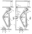
- the device for separating of vegetables and root-crops from admixtures comprises a transporter 1 (fig. 1) for moving vegetables to the separator, its shaft is fixed on the frame 5 of the device with the help of a bush 3 and fasteners 4.
- the main transporter 6 fixed by the shaft 8 on the frame 5 with the help of a bush 9 and fasteners 10 has protruding fingers 7. It is mounted with the angle to the horizon.
- the transporter 6 is made so that it has at least one bend part 12 of the upper bed 13. This is realized with the help of the upper bed 13 tensioner which comprises a roller 14 placed on the frame 5.
- Fig. 2 shaws transporter 6' with three bend parts 11, 12', 12'' and some inclined parts on the upper bed 13 which are formed by the corresponding rollers 14 of the upper bed tensioner, placed along the transporter 6'.
- Each roller 14 is fixed in a slot 15 of the frame 5 so that it can move along the slot 15 to regulate the pitch length and the angle on the corresponding inclined parts.
- a brush drum 16 (fig. 3) is placed in the zone of the last inclined part of the upper bed 13 . Its shaft 17 is fixed on the frame 5 with the help of a bush 18 and fasteners 19. The position of the drum 16 to the transporter 6 can be regulated.
- All the inclined parts of the transporter 6 are made so that the angle of obliquity of the bed 13 is smaller than the angle of friction of the admixtures on the transporter 6. It allows the admixtures to move along the transporter up to the moment of their separation and not to roll down to the zone where the separating mass is moved to.
- the angle of obliquity of at least one of the dropping down inclined parts of the upper bed must be equal or bigger than the angle of friction of vegetables on the transporter 6. If the angle of obliquity is smaller than the angle of friction, the vegetables will be stopped on the dropping down inclined part of the transporter 6, and the quality of the separation will deteriorate.
- An element of the forced plunging of the separating products is placed between the fingers 7 of the transporter 6. It comprises the transporter 20 (fig. 4) or a bent plate 21 (fig. 5).
- the shaft 22 (fig. 4) of the transporter 20 is fixed in the bush 23 on the frame 5 and the shaft 25 is fixed in the slot 25 of the frame 5 so as they can move changing the distance between the bed 26 of the transporter 20 and the upper bed 13 of the transporter 6.
- the plate 21 (fig. 5) is fixed on the frame 5 and its convex side faces the transporter 6.
- the transporter 20 (fig. 4) and the plate 21 (fig. 5) are placed over one or some bend parts 12 of the upper bed 13 of the transporter 6.
- the rod 27 and its corresponding fingers 7 should be made a single unit as it is shown on fig. 6.
- the fingers 7 on the rod 27 are placed one relatively another and fingers 7 of the next rod 27 so as the formed cells are smaller than the average size of the separated vegetables.
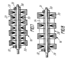
- the brush drum 16 (fig. 7) is made of sections to raise the effeciency of the separation. All the sections 29 (fig. 7) are mounted on the shaft 30 where they are fixed by bushes 31 and screws 32.
- the sections 29 have hair 33 of different length and hardness alternating with one another along the shaft 30. Besides one or some sections 29 (fig. 8) have blades 34 instead of hair 33. It improves the separating process greatly. Sections 29 alternate along the shaft 30 with sections 29 and blades 34 have the height lower than that of the hair 33.
- blades 35 may be placed on one section 29 with the hair 33 and alternate with the sections of the hair 33.
- the hardness of the hair 33 must be weaker than that of the fingers 7 lest vegetables should be damaged.
- Fingers 7' (fig. 10) have be shape of a truncated cone or a truncated pyramid and they are fixed on the rods 27 of the transporter 6 by means of their small foundation.
- fingers 28 (fig. 11) and 28' have different height that provides the efficient separation of different vegetables and root-crops.
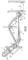
- a transporter 1 (fig. 12) is made of the same kind with the transporter 6 and it is mounted in front of the transporter 6 as inclined to the horizon. It is fixed with the bushes 9 on the frame 5 and has its own drive 36 and protruding fingers 37.
- the device for limiting of the zone of appearance of the products for separation on the transporter 6. It comprises a shaft 38 with protruding fingers 39 on it which are placed so that the fingers 7 and 35 alternate while the transporter 6 and shaft 38 are both moving.
- the shaft 38 is fixed on the frame 5 by the fasteners 40.
- a device of shaking (a shaker) 41 is placed near one of the dropping down parts of the transporter 6.
- This device 41 has an eccentric shaft 42 interacting with the upper bed 13 of the transporter 6.
- the device 43 for deviding of vegetables and admixtures is placed. It comprises a foundation 44 and prodtruding rods 45.
- the foundation 44 is fixed on hinges on the frame 5 of the device with the help of a screw-nut 46 ensuring to regulate the going out of the hair 33 (fig. 7) over the rods 45 (fig. 14) in the zone where separating products contact the brush drum 16.
- the rods 45 are directed to the brush drum 16 and form a comb with step A (fig. 15). Rods 45 and hair sections 33 of the drum 16 alternate each other.
- the amortizating plate 47 (fig. 16, 17) may be placed and fixed on the frame 5 as regulating the angle of obliquity.
- the plate 47 has a drive of horizontal travel across the brush drum 16.
- the transporter 11 is placed perpendicularly and inclinedly to the drum 16.
- the device for separating of vegetables and root-crops from admixtures works as follows.
- the vegetables move along the transporter 6 to the zone 49 at the end of which all the components of the vegetable heap rest.
- the regulated angle of the inclined upper bed zone permits the vegetable heap to move to the zone 50 not more as of one stratum.
- the soil clods are clutch in the zone 51 by elastic fingers 7. At that moment the expulsive force is less than the force of friction and of gravity, and the soil clods are moved to the zone 47 of the transporter 6. Due to the compressive force of the fingers 7 some admixtures are damaged and moved away through the clearance between the rods 28 (fig. 6).
- the fingers 7 will go on moving apart and pressing if the transporter 6 has several bend parts, as it is shown on fig. 2.
- the larger part of the admixtures is damaged because the different up and down angles of the upper bed 13 influence the compressive force on different parts of the bed.
- sections 29 have hair 33 of different hardness and length, and the hardness of the hair 33 is weaker than that one of the fingers 7, the conditions of the separation improve.
- the interrod space of the comb is constantly cleared by the hair of the brush drum 16.
- the using of an active toothed rack made of rotating hoops with the same interrod space is quite possible.
- the diametrical angle of the transporter 11 is best of all fixed as a sharp one relatively to the vertical line and its upper plane. When the vegetable ratio in the heap, led from the transporter 6 is rather high, this angle must be an obtuse one. This helps vegetables to roll down from the zone where the brush drum acts when the products of separation are drawn aside diametrically.
- ammortizating plate 47 (fig. 16, 17) is mounted behind the brush drum 16 and near, soil and vegetable admixtures, as well as damaged fruits, which have a small coefficient of restoration in comparison with standard vegetables found themselves under the influence of the brush drum's hair capture force. They are drawn away by the hair towards the brush drum's rotating. Standard vegetables leave this zone because of the considerable coefficient of their restoration and they are led to the transporter 11.
- the device for separating of vegetables and root-crops from admixtures is universal and may be used independently or as a part of agricultural harvesting combines.
- the efficiency of the device is very high, it forms no less than 85-95%.
- This invention may be used for the harvesting and separating from admixtures of potatoes and jucy vegetables like tomatoes, egg-plants and peppers.
Applications Claiming Priority (1)
| Application Number | Priority Date | Filing Date | Title |
|---|---|---|---|
| PCT/UA1993/000006 WO1995015075A1 (fr) | 1993-12-02 | 1993-12-02 | Dispositif de separation de fruits et de racines alimentaires d'une matiere etrangere |
Publications (2)
| Publication Number | Publication Date |
|---|---|
| EP0699380A4 EP0699380A4 (de) | 1996-02-27 |
| EP0699380A1 true EP0699380A1 (de) | 1996-03-06 |
Family
ID=21688689
Family Applications (1)
| Application Number | Title | Priority Date | Filing Date |
|---|---|---|---|
| EP94905307A Withdrawn EP0699380A1 (de) | 1993-12-02 | 1993-12-02 | Vorrichtung um früchte und rüben von fremdstoffen zu trennen |
Country Status (3)
| Country | Link |
|---|---|
| US (1) | US5735740A (de) |
| EP (1) | EP0699380A1 (de) |
| WO (1) | WO1995015075A1 (de) |
Families Citing this family (6)
| Publication number | Priority date | Publication date | Assignee | Title |
|---|---|---|---|---|
| US6868659B2 (en) * | 2001-01-26 | 2005-03-22 | Arbuckle Ranch, Inc. | Native seed harvester with cam design |
| EP1310148B1 (de) * | 2001-11-07 | 2008-09-03 | Holmer Maschinenbau GmbH | Erntemaschine |
| US20100163257A1 (en) * | 2008-12-31 | 2010-07-01 | Weyerhaeuser Company | Seedling harvesting apparatus |
| RU2454850C1 (ru) * | 2011-02-14 | 2012-07-10 | Федеральное государственное образовательное учреждение высшего профессионального образования "Рязанский государственный агротехнологический университет имени П.А. Костычева" | Устройство для отделения корнеклубнеплодов от примесей |
| US8573388B2 (en) * | 2011-10-31 | 2013-11-05 | Deere & Company | Conveyor belt tensioner for an agricultural harvesting header |
| US11818983B2 (en) | 2014-09-21 | 2023-11-21 | Bridgestone Corporation | Guayule harvester and related processes |
Citations (5)
| Publication number | Priority date | Publication date | Assignee | Title |
|---|---|---|---|---|
| FR1237568A (fr) * | 1959-01-30 | 1960-07-29 | Max Kohout | Machine pour récolter les tubercules et autres racines |
| DE1136152B (de) * | 1954-08-06 | 1962-09-06 | Heinrich Hall | Vorrichtung zum Trennen von Hackfruechten, insbesondere Kartoffeln, von Steinen und Erdklumpen |
| DE2610380A1 (de) * | 1976-03-12 | 1977-09-15 | Grimme Landmaschf Franz | Trennvorrichtung fuer kartoffelerntemaschinen |
| DE3810602A1 (de) * | 1988-03-29 | 1989-10-19 | Christoph Welp | Kartoffelerntemaschine |
| US5069292A (en) * | 1990-09-21 | 1991-12-03 | Baker Henry A | Method for soil clod/root crop separation |
Family Cites Families (7)
| Publication number | Priority date | Publication date | Assignee | Title |
|---|---|---|---|---|
| US3810512A (en) * | 1972-12-01 | 1974-05-14 | W Porter | Harvesting apparatus for removing crops from plants or vines |
| HU168368B (de) * | 1973-10-20 | 1976-04-28 | ||
| US4284145A (en) * | 1977-09-10 | 1981-08-18 | Tonparo Limited | Separator device |
| SU1576005A1 (ru) * | 1988-03-02 | 1990-07-07 | Научно-производственное объединение по сельскохозяйственному машиностроению | Устройство дл отделени примесей от клубней картофел |
| SU1583018A1 (ru) * | 1988-04-15 | 1990-08-07 | Научно-Производственное Объединение По Сельскохозяйственному Машиностроению "Висхом" | Устройство дл отделени корнеклубнеплодов от примесей |
| SU1727658A1 (ru) * | 1989-02-22 | 1992-04-23 | Головное Специализированное Конструкторское Бюро Производственного Объединения "Молдсельмаш" | Комбайн дл уборки томатов |
| US5099636A (en) * | 1990-09-13 | 1992-03-31 | Yoder Joseph A | Vinous row crop harvesting apparatus and methods |
-
1993
- 1993-12-02 WO PCT/UA1993/000006 patent/WO1995015075A1/ru not_active Application Discontinuation
- 1993-12-02 EP EP94905307A patent/EP0699380A1/de not_active Withdrawn
- 1993-12-02 US US08/564,291 patent/US5735740A/en not_active Expired - Fee Related
Patent Citations (5)
| Publication number | Priority date | Publication date | Assignee | Title |
|---|---|---|---|---|
| DE1136152B (de) * | 1954-08-06 | 1962-09-06 | Heinrich Hall | Vorrichtung zum Trennen von Hackfruechten, insbesondere Kartoffeln, von Steinen und Erdklumpen |
| FR1237568A (fr) * | 1959-01-30 | 1960-07-29 | Max Kohout | Machine pour récolter les tubercules et autres racines |
| DE2610380A1 (de) * | 1976-03-12 | 1977-09-15 | Grimme Landmaschf Franz | Trennvorrichtung fuer kartoffelerntemaschinen |
| DE3810602A1 (de) * | 1988-03-29 | 1989-10-19 | Christoph Welp | Kartoffelerntemaschine |
| US5069292A (en) * | 1990-09-21 | 1991-12-03 | Baker Henry A | Method for soil clod/root crop separation |
Non-Patent Citations (1)
| Title |
|---|
| See also references of WO9515075A1 * |
Also Published As
| Publication number | Publication date |
|---|---|
| US5735740A (en) | 1998-04-07 |
| EP0699380A4 (de) | 1996-02-27 |
| WO1995015075A1 (fr) | 1995-06-08 |
Similar Documents
| Publication | Publication Date | Title |
|---|---|---|
| EP0699380A1 (de) | Vorrichtung um früchte und rüben von fremdstoffen zu trennen | |
| US3070944A (en) | Harvesting apparatus | |
| US4375853A (en) | Apparatus for separating clods and agricultural products | |
| US4385702A (en) | Vibrating separator | |
| US5069292A (en) | Method for soil clod/root crop separation | |
| CN104128310A (zh) | 两级弹跳油茶果籽壳分选机 | |
| EP0548192B1 (de) | Knollenscheider | |
| EP0705150B1 (de) | Sortiervorrichtung | |
| GB2067434A (en) | Potato harvester | |
| RU2080765C1 (ru) | Комбайн для уборки овощей | |
| EP0562541B1 (de) | Trennvorrichtung zum Abtrennen der Tochterzwiebeln und/oder der Wurzel von Blumenzwiebeln | |
| US4009783A (en) | Friction separator | |
| US3833065A (en) | Haulm plucker | |
| US3682303A (en) | Machine for continuously removing over-sized undesirable material from crop material mixtures | |
| US3269535A (en) | Shuffle feed sorting structure | |
| RU2080766C1 (ru) | Комбайн "таки" для уборки овощей, преимущественно томатов и корнеклубнеплодов | |
| RU2194380C2 (ru) | Устройство для очистки и сортировки корнеклубнеплодов и фруктов | |
| US3469688A (en) | Grain scalper | |
| RU2004112C1 (ru) | Устройство дл отделени почвенных комков от корнеклубнеплодов и томатов | |
| RU35053U1 (ru) | Комбайн "ТаКи" для уборки овощей, преимущественно томатов и корнеклубнеплодов | |
| RU2073406C1 (ru) | Устройство для очистки и сортировки корнеклубнеплодов и фруктов | |
| RU2295221C2 (ru) | Малогабаритный многофункциональный картофелеуборочный комбайн с отделителем и накопителем мелких клубней | |
| DE2003215C2 (de) | Mähdrescher | |
| RU2271092C2 (ru) | Сортировка барабанного типа | |
| SU967350A1 (ru) | Устройство дл отделени корнеклубнеплодов от камней и комков почвы |
Legal Events
| Date | Code | Title | Description |
|---|---|---|---|
| PUAI | Public reference made under article 153(3) epc to a published international application that has entered the european phase |
Free format text: ORIGINAL CODE: 0009012 |
|
| A4 | Supplementary search report drawn up and despatched | ||
| AK | Designated contracting states |
Kind code of ref document: A4 Designated state(s): DE FR GB IT |
|
| 17P | Request for examination filed |
Effective date: 19950818 |
|
| AK | Designated contracting states |
Kind code of ref document: A1 Designated state(s): DE FR GB IT |
|
| 17Q | First examination report despatched |
Effective date: 19981005 |
|
| STAA | Information on the status of an ep patent application or granted ep patent |
Free format text: STATUS: THE APPLICATION IS DEEMED TO BE WITHDRAWN |
|
| 18D | Application deemed to be withdrawn |
Effective date: 19990416 |