US4385702A - Vibrating separator - Google Patents
Vibrating separator Download PDFInfo
- Publication number
- US4385702A US4385702A US06/290,542 US29054281A US4385702A US 4385702 A US4385702 A US 4385702A US 29054281 A US29054281 A US 29054281A US 4385702 A US4385702 A US 4385702A
- Authority
- US
- United States
- Prior art keywords
- belt
- objects
- frame
- fingers
- vibration
- Prior art date
- Legal status (The legal status is an assumption and is not a legal conclusion. Google has not performed a legal analysis and makes no representation as to the accuracy of the status listed.)
- Expired - Fee Related
Links
Images


Classifications
-
- B—PERFORMING OPERATIONS; TRANSPORTING
- B07—SEPARATING SOLIDS FROM SOLIDS; SORTING
- B07B—SEPARATING SOLIDS FROM SOLIDS BY SIEVING, SCREENING, SIFTING OR BY USING GAS CURRENTS; SEPARATING BY OTHER DRY METHODS APPLICABLE TO BULK MATERIAL, e.g. LOOSE ARTICLES FIT TO BE HANDLED LIKE BULK MATERIAL
- B07B13/00—Grading or sorting solid materials by dry methods, not otherwise provided for; Sorting articles otherwise than by indirectly controlled devices
- B07B13/10—Grading or sorting solid materials by dry methods, not otherwise provided for; Sorting articles otherwise than by indirectly controlled devices using momentum effects
- B07B13/11—Grading or sorting solid materials by dry methods, not otherwise provided for; Sorting articles otherwise than by indirectly controlled devices using momentum effects involving travel of particles over surfaces which separate by centrifugal force or by relative friction between particles and such surfaces, e.g. helical sorters
- B07B13/116—Grading or sorting solid materials by dry methods, not otherwise provided for; Sorting articles otherwise than by indirectly controlled devices using momentum effects involving travel of particles over surfaces which separate by centrifugal force or by relative friction between particles and such surfaces, e.g. helical sorters stratification of dry granular material on a continuously travelling surface, e.g. belt conveyor
-
- A—HUMAN NECESSITIES
- A23—FOODS OR FOODSTUFFS; TREATMENT THEREOF, NOT COVERED BY OTHER CLASSES
- A23N—MACHINES OR APPARATUS FOR TREATING HARVESTED FRUIT, VEGETABLES OR FLOWER BULBS IN BULK, NOT OTHERWISE PROVIDED FOR; PEELING VEGETABLES OR FRUIT IN BULK; APPARATUS FOR PREPARING ANIMAL FEEDING- STUFFS
- A23N12/00—Machines for cleaning, blanching, drying or roasting fruits or vegetables, e.g. coffee, cocoa, nuts
- A23N12/005—Machines for cleaning, blanching, drying or roasting fruits or vegetables, e.g. coffee, cocoa, nuts for dry-cleaning
-
- B—PERFORMING OPERATIONS; TRANSPORTING
- B07—SEPARATING SOLIDS FROM SOLIDS; SORTING
- B07B—SEPARATING SOLIDS FROM SOLIDS BY SIEVING, SCREENING, SIFTING OR BY USING GAS CURRENTS; SEPARATING BY OTHER DRY METHODS APPLICABLE TO BULK MATERIAL, e.g. LOOSE ARTICLES FIT TO BE HANDLED LIKE BULK MATERIAL
- B07B13/00—Grading or sorting solid materials by dry methods, not otherwise provided for; Sorting articles otherwise than by indirectly controlled devices
-
- Y—GENERAL TAGGING OF NEW TECHNOLOGICAL DEVELOPMENTS; GENERAL TAGGING OF CROSS-SECTIONAL TECHNOLOGIES SPANNING OVER SEVERAL SECTIONS OF THE IPC; TECHNICAL SUBJECTS COVERED BY FORMER USPC CROSS-REFERENCE ART COLLECTIONS [XRACs] AND DIGESTS
- Y02—TECHNOLOGIES OR APPLICATIONS FOR MITIGATION OR ADAPTATION AGAINST CLIMATE CHANGE
- Y02A—TECHNOLOGIES FOR ADAPTATION TO CLIMATE CHANGE
- Y02A40/00—Adaptation technologies in agriculture, forestry, livestock or agroalimentary production
- Y02A40/90—Adaptation technologies in agriculture, forestry, livestock or agroalimentary production in food processing or handling, e.g. food conservation
Definitions
- This invention relates to and has among its objects the provision of a novel apparatus for separating objects of different sizes or shapes and finds particular use in separating fruits, vegetables and other agricultural crops from twigs, leaves and other trash.
- the invention described herein provides a means for separating objects on the basis of shape and size and finds particular use in separating sticks and trash from fruit and vegetable crops.
- a conveyor belt having upwardly projecting fingers is fixed to a frame. Also mounted on the frame are means for vibrating the belt and attached fingers.
- the fingers are spaced such that objects of a particular size or shape are entrapped therein and conveyed in the direction of the movement of the belt while objects of a different size or shape are supported on the ends of the fingers and conveyed by vibration over the ends of the fingers in a direction different from the direction of the movement of the conveyor belt, thereby separating the entrapped objects from the supported objects.
- the primary advantage of the invention is the separation of objects with different shapes or dimensions, particularly those objects not susceptible to separation by usual methods such as screening, sieving, air separation and the like.
- One particular advantage is that fruits or vegetables can be readily separated from intermixed twigs, leaves, roots and other trash.
- the invention finds utility wherever separation of objects having dissimilar shape or size is desired.
- the invention can readily be used in combination with mechanical harvesting devices which remove fruit or vegetables from plants or trees or which mechanically pick up crops which have fallen on the ground. Considerable time and expense of hand labor necessary to separate a crop from comingled trash are saved, thus, reducing the price of the final product or loss of the product due to unavailability of hand labor.
- Another important advantage of the invention is that it can be used in the field. Money and energy are saved as only the fruit and vegetables harvested need be transported. The trash can be left in the field and used as mulch.
- FIG. 1 is a side view of a particular embodiment of the invention.
- FIG. 2 is an end view of the embodiment of FIG. 1 with the conveyor belt removed.
- FIG. 3 is a side view of an embodiment.
- FIG. 4 is an end view of the embodiment of FIG. 3.
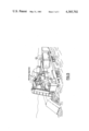
- FIG. 5 is a view of the invention incorporated into a mechanical harvester.
- main frame 1 flexibly supports belt frame 2 by means of flexible strips 3 which are fixedly attached to main frame 1 at 4 and the belt frame 2 at 5.
- Shafts 8 and 9 to which pulleys 6 and 7 are fixedly attached are rotatively journaled to belt frame 2.
- Conveyor belt 10 surrounds pulleys 6 and 7 and has upwardly projecting fingers 11 attached thereto.
- Curved belt frame member 12 is affixed to belt frame 2 and supports belt 10 in the separating area 13 so that belt 10 remains snug against belt frames 12 and 2 and pulleys 6 and 7 and vibrates with frame 2 and 12 and not independently therefrom.
- Belt 10 is moved by turning sheave 18, attached to shafts 8, by means of motor 14, shaft 15, pulleys 16 and belt 17.
- Weights 27 located on shaft 26 are eccentrically affixed thereto;
- sprocket 28 is concentrically affixed to shaft 26.
- Chain drive 31 surrounds sprocket 28, contacts one side of sprocket 29, and surrounds idler 30 which is connected to belt frame 2 through a bearing.
- Shaft 33 is journaled to belt frame 2; weights 32 are eccentrically attached to shaft 33 and sprocket 29 is concentrically attached to shaft 33.
- weights 27 along the length of shaft 26 and of weights 32 on shaft 33 is not critical; however, weights 27 must be equidistant from the centerline of belt frame 2 and weights 32 must be equidistant from the centerline of belt frame 2.
- Weights 27a and b are positioned on shaft 25 in relation to each other so that they work in synchrony, that is if weight 27a was superimposed on 27b, the position of eccentricity of both weights would be substantially the same.
- Weights 32a and b are positioned on shaft 31 so that they rotate in synchrony and in a direction opposite to the rotation of weights 27a and b. It is desirable that the eccentric most position of weights 27a and b and the eccentric most position of weights 32a and b are opposite during rotation so that the vibration will be in a direction substantially perpendicular to the flexible strips 3.
- Spring 34 is attached to belt frame 2 and main frame 1; it applies sufficient force to keep the flexible strips 3 straight when the machine is at rest. The spring constant of spring 34 must be small enough to prevent excessive vibration from being transmitted to frame 1.
- the objects to be separated are fed onto belt 10 by any conventional means.
- Motor 14 rotates shaft 15 and affixed pulley 16 thereby driving belt 17 and sheave 18.
- Objects of a size and shape small enough to fit between the fingers are entrapped in the fingers and are conveyed in the direction of the movement of the belt.
- motor 20 causes shaft 26 to rotate by the rotation of shaft 21, pulleys 22 and 25, and belt 23, thereby causing eccentric weights 27 to rotate.
- Shaft 26 drives sprocket 28, chain drive 31 and sprocket 29 to cause shaft 33 and affixed eccentric weights 32 to rotate in a direction opposite the rotation of weights 27.
- These counter-rotating eccentric weights are driven and synchronized to cause belt frame 2 which is suspended on flexible strips 3 to vibrate in a direction substantially perpendicular to flexible strips 3 as shown by the double ended arrow and convey by vibration the objects supported on the fingers in a direction opposite to the movement of the belt.
- Flexible strips 3 are made of material such as conventional belt material and the like and allow belt frame 2 to vibrate without transmitting excessive vibration to main frame 1, that is, vibration which would create undesirable noise and vibration if the invention were attached to a harvesting device or free standing.
- Upwardly projecting fingers 11 fixedly attached to conveyor belt 10 are spaced at intervals so that objects of a particular size or shape are entrapped by the fingers and carried in the direction of the movement of the belt and objects to be separated which have a different shape or size are prevented from falling between the fingers.
- the supported objects are vibrated across the ends of the fingers in a direction other than the direction of the belt.
- the spacing dimensions of the fingers are dependent on the sizes and shapes of objects to be separated.
- the length of the fingers is not critical, however, they should be long enough to entrap objects and prevent them from being dislodged by vibration.
- the fingers should be close enough together to support the other objects so that the supported objects are conveyed by vibration along the surface of the fingers without being hindered by the entrapped objects.
- the fingers should not be so long as to vibrate excessively, that is, to a degree that the entrapped objects are dislodged.
- the fingers are at an angle to the belt to assist in preventing dislodgement of the entrapped objects by vibration.
- Angling is of particular importance when the belt is used at high vibration speeds. The degree of angling depends on the size and shape of the objects to be separated, that is, the angle should be such that the supported objects are supported on and vibrated across the projecting fingers in one direction while the objects to be entrapped caught by the fingers and conveyed by the belt in another direction.
- the movement of conveyance by vibration is opposite (180 degrees) to the movement of the belt.
- shaft 8 is connected through universal joint 36 to shaft 19 which is affixed to sheave 18.
- the movement of the entrapped objects is not directly opposed to the supported objects thus hindrance of the movement of conveyed (supported) objects by entrapped objects is lessened.
- the belt movement and vibration conveyance movement could be arranged at other angles as desired; the critical feature is that the angle be sufficient to separate the entrapped and supported objects.
- FIG. 1 depicts a sloped belt to aid in vibration conveyance This is not a critical feature, however; the belt may be level or sloped in the opposite direction if changes in the belt slope are compensated for by changes in vibration frequency.
- the critical feature is that the vibration conveyance movement and belt movement are adjusted to be sufficiently different to separate the entrapped objects from those supported and conveyed by vibration on the fingers.
- the counter-rotating eccentric weights could be replaced by a crank shaft journaled to main frame 1 and rotatively connected to a connecting rod which was rotatively mounted on belt frame 2 so that rotation of the crank shaft would cause the connecting rod to move and vibrate the belt frame, conveyance belt and affixed fingers.
- Flexible strips 3 could be replaced by pivot bars journaled to the main frame 1 at one end and to belt frame 2 at the other to allow vibration of the belt frame.
- the apparatus is used either free standing or incorporated into a mechanical harvester (FIG. 5) which picks up fruit or vegetables intermixed with twigs, leaves and other trash and feeds this mixture onto the vibrating separator.
- a mechanical harvester FIG. 5
- Collecting bins are placed at required points to collect the separated objects. Where trash is separated from fruit or vegetables in the field, the trash may be left in the field and used as mulch.
- This invention is further illustrated by the separation of chili peppers from sticks, leaves and other trash.
- This example is by way of illustration and not limitation.
- the invention also finds use to separate other vegetables such as tomatoes, other chili varieties, and fruits such as oranges, apples, and the like from leaves and twigs. It also could be used to separate objects other than agricultural produce.
- the only criteria is that the size differential be sufficient to allow objects to be supported on the belt fingers and conveyed by vibration and other objects to be entrapped by the fingers.
- FIGS. 1 and 2 Two kg of red chili peppers containing intermixed sticks, leaves, dirt and other trash was fed onto the invention in FIGS. 1 and 2.
- the counter-rotating eccentric weights were driven to vibrate the belt frame and belt with a stroke of about 1.5 cm at a frequency of 710 cpm in a direction perpendicular to the flexible strips.
- the belt which was 90 cm long and 60 cm wide traveled over a support member (12) having a curvature of 7.6 m radius, thereby insuring that the belt vibrated with the belt frame in a controlled manner.
- the angle between the direction of vibration and the plane of the belt was maintained at 36 degrees and should be 23 to 47 degrees.
- the slope of the belt frame was maintained at 17 degrees and should be 5 to 25 degrees.
- the rubber fingers were 3.1 cm long and had a diameter of 0.63 cm at the base and 0.32 cm at the tip.
- the fingers were angled at 54 degrees measured from the plane of the belt to a plane passing lengthwise through the finger.
- the fingers were spaced so that the distance between fingers in the same row and the distance between rows was 2.5 cm.
- Fingers in alternate rows were positioned along a line perpendicular to the width of the belt at substantially identical points. Fingers in a row were positioned midway between the fingers of adjacent rows.
Abstract
Description
Claims (4)
Priority Applications (1)
| Application Number | Priority Date | Filing Date | Title |
|---|---|---|---|
| US06/290,542 US4385702A (en) | 1981-08-06 | 1981-08-06 | Vibrating separator |
Applications Claiming Priority (1)
| Application Number | Priority Date | Filing Date | Title |
|---|---|---|---|
| US06/290,542 US4385702A (en) | 1981-08-06 | 1981-08-06 | Vibrating separator |
Publications (1)
| Publication Number | Publication Date |
|---|---|
| US4385702A true US4385702A (en) | 1983-05-31 |
Family
ID=23116480
Family Applications (1)
| Application Number | Title | Priority Date | Filing Date |
|---|---|---|---|
| US06/290,542 Expired - Fee Related US4385702A (en) | 1981-08-06 | 1981-08-06 | Vibrating separator |
Country Status (1)
| Country | Link |
|---|---|
| US (1) | US4385702A (en) |
Cited By (13)
| Publication number | Priority date | Publication date | Assignee | Title |
|---|---|---|---|---|
| US5802965A (en) * | 1997-02-19 | 1998-09-08 | Lin; Pao-Tseng | Bean sprout processing apparatus |
| US6003293A (en) * | 1996-09-25 | 1999-12-21 | Boese; Gregory M. | Vegetable harvester |
| EP0956781A3 (en) * | 1998-05-15 | 2000-04-05 | Daisei Machinery Co., Ltd. | Sprouting beans refining apparatus |
| US6050073A (en) * | 1997-03-17 | 2000-04-18 | Griffin Produce Inc. | Harvester and method of harvesting leafy vegetables |
| US6199703B1 (en) | 1997-09-24 | 2001-03-13 | Gregory M. Boese | Vegetable harvester |
| US6378281B1 (en) | 2000-08-09 | 2002-04-30 | James Ottaway | Method and apparatus for harvesting lettuce |
| US20030159647A1 (en) * | 2002-02-20 | 2003-08-28 | Arvidson Arvid Neil | Flowable chips and methods for the preparation and use of same, and apparatus for use in the methods |
| NL1020994C2 (en) * | 2002-07-03 | 2004-01-06 | Ploeger Agro B V | Sorting machine for different shaped objects, e.g. peas, has object supporting part of conveyor belt movable backwards and forwards at frequency independent of belt speed |
| US20040251351A1 (en) * | 2001-07-05 | 2004-12-16 | Paul Douglas | Screening plant system |
| US20090133414A1 (en) * | 2003-08-26 | 2009-05-28 | Jan Vetrovec | Autonomous water source |
| US7555888B1 (en) | 2008-03-18 | 2009-07-07 | Boese Aaron M | Pull type pepper harvester |
| US20100132326A1 (en) * | 2007-07-31 | 2010-06-03 | Jean-Paul Berthet | Separator device and cleaning system for a stream harvested by a fruit harvesting machine |
| US20110042278A1 (en) * | 2009-08-19 | 2011-02-24 | Janssen Bill M | Method and apparatus for separating fines from rock |
Citations (6)
| Publication number | Priority date | Publication date | Assignee | Title |
|---|---|---|---|---|
| US1747625A (en) * | 1927-05-16 | 1930-02-18 | Gudmundsen Abraham | Beet cleaner |
| US2116006A (en) * | 1936-06-17 | 1938-05-03 | Thys Edouard | Hop and stem separator |
| US2788124A (en) * | 1952-03-19 | 1957-04-09 | Rca Corp | Sorting apparatus |
| US2964180A (en) * | 1959-02-11 | 1960-12-13 | Leo L Holzeuthal | Cottonseed cleaner |
| US3612272A (en) * | 1970-03-09 | 1971-10-12 | Samuel S Aidlin | Separator-conveyor |
| US4009783A (en) * | 1975-10-02 | 1977-03-01 | The United States Of America As Represented By The Secretary Of Agriculture | Friction separator |
-
1981
- 1981-08-06 US US06/290,542 patent/US4385702A/en not_active Expired - Fee Related
Patent Citations (6)
| Publication number | Priority date | Publication date | Assignee | Title |
|---|---|---|---|---|
| US1747625A (en) * | 1927-05-16 | 1930-02-18 | Gudmundsen Abraham | Beet cleaner |
| US2116006A (en) * | 1936-06-17 | 1938-05-03 | Thys Edouard | Hop and stem separator |
| US2788124A (en) * | 1952-03-19 | 1957-04-09 | Rca Corp | Sorting apparatus |
| US2964180A (en) * | 1959-02-11 | 1960-12-13 | Leo L Holzeuthal | Cottonseed cleaner |
| US3612272A (en) * | 1970-03-09 | 1971-10-12 | Samuel S Aidlin | Separator-conveyor |
| US4009783A (en) * | 1975-10-02 | 1977-03-01 | The United States Of America As Represented By The Secretary Of Agriculture | Friction separator |
Cited By (19)
| Publication number | Priority date | Publication date | Assignee | Title |
|---|---|---|---|---|
| US6419093B2 (en) | 1996-09-25 | 2002-07-16 | Gregory M. Boese | Vegetable harvester |
| US6003293A (en) * | 1996-09-25 | 1999-12-21 | Boese; Gregory M. | Vegetable harvester |
| US5802965A (en) * | 1997-02-19 | 1998-09-08 | Lin; Pao-Tseng | Bean sprout processing apparatus |
| US6050073A (en) * | 1997-03-17 | 2000-04-18 | Griffin Produce Inc. | Harvester and method of harvesting leafy vegetables |
| US6199703B1 (en) | 1997-09-24 | 2001-03-13 | Gregory M. Boese | Vegetable harvester |
| EP0956781A3 (en) * | 1998-05-15 | 2000-04-05 | Daisei Machinery Co., Ltd. | Sprouting beans refining apparatus |
| US6622467B1 (en) | 2000-08-09 | 2003-09-23 | James Ottaway | Method for harvesting lettuce |
| US6378281B1 (en) | 2000-08-09 | 2002-04-30 | James Ottaway | Method and apparatus for harvesting lettuce |
| US20040251351A1 (en) * | 2001-07-05 | 2004-12-16 | Paul Douglas | Screening plant system |
| US20030159647A1 (en) * | 2002-02-20 | 2003-08-28 | Arvidson Arvid Neil | Flowable chips and methods for the preparation and use of same, and apparatus for use in the methods |
| US8021483B2 (en) | 2002-02-20 | 2011-09-20 | Hemlock Semiconductor Corporation | Flowable chips and methods for the preparation and use of same, and apparatus for use in the methods |
| NL1020994C2 (en) * | 2002-07-03 | 2004-01-06 | Ploeger Agro B V | Sorting machine for different shaped objects, e.g. peas, has object supporting part of conveyor belt movable backwards and forwards at frequency independent of belt speed |
| US20090133414A1 (en) * | 2003-08-26 | 2009-05-28 | Jan Vetrovec | Autonomous water source |
| US7866176B2 (en) * | 2003-08-26 | 2011-01-11 | Aqwest Llc | Autonomous water source |
| US20100132326A1 (en) * | 2007-07-31 | 2010-06-03 | Jean-Paul Berthet | Separator device and cleaning system for a stream harvested by a fruit harvesting machine |
| US8123598B2 (en) * | 2007-07-31 | 2012-02-28 | Cnh America Llc | Separator device and cleaning system for a stream harvested by a fruit harvesting machine |
| US7555888B1 (en) | 2008-03-18 | 2009-07-07 | Boese Aaron M | Pull type pepper harvester |
| US20110042278A1 (en) * | 2009-08-19 | 2011-02-24 | Janssen Bill M | Method and apparatus for separating fines from rock |
| US8322538B2 (en) | 2009-08-19 | 2012-12-04 | Janssen Bill M | Method and apparatus for separating fines from rock |
Similar Documents
| Publication | Publication Date | Title |
|---|---|---|
| US4335570A (en) | Harvesting shaker for crops such as tomatoes or the like | |
| US4385702A (en) | Vibrating separator | |
| US5846129A (en) | Apparatus and method for separating produce from their vines | |
| US3199604A (en) | Tomato harvester | |
| EP0620705B1 (en) | Vinous row crop harvesting apparatus | |
| US4174755A (en) | Agitator assembly for a fruit-vine separator | |
| US5702301A (en) | Two stage shaker | |
| US3070944A (en) | Harvesting apparatus | |
| US6282877B1 (en) | Fruit and vegetable harvesting apparatus and methods | |
| US6257978B1 (en) | Food plant harvester with improved recovery system | |
| US4787461A (en) | Shaker assembly | |
| US7051505B2 (en) | Tomato harvester | |
| US4175621A (en) | Fruit dislodger for a harvesting machine | |
| US3618617A (en) | Separator for tomato harvester and the like | |
| US3613796A (en) | Selective sort vine crop harvester | |
| US3566881A (en) | Tomato harvester shaking mechanism | |
| US3666017A (en) | Separator for tomato harvester and the like | |
| US4244165A (en) | Harvester apparatus | |
| US3286774A (en) | Tomato harvester | |
| US3656488A (en) | Turnover shaker | |
| US3353342A (en) | Harvester pickup | |
| US4060133A (en) | Method for mechanically harvesting tomatoes | |
| US2902997A (en) | Peanut stripper | |
| US3203430A (en) | Separating conveyor for a tomato harvester | |
| US3455453A (en) | Tomato harvester separator |
Legal Events
| Date | Code | Title | Description |
|---|---|---|---|
| AS | Assignment |
Owner name: UNITED STATES OF AMERICA AS REPRESENTED BY THE SEC Free format text: ASSIGNMENT OF ASSIGNORS INTEREST.;ASSIGNORS:LENKER, DON H.;NASCIMENTO, DENNIS F.;REEL/FRAME:003907/0979 Effective date: 19810717 Owner name: UNITED STATES OF AMERICA AS REPRESENTED BY THE SEC Free format text: ASSIGNMENT OF ASSIGNORS INTEREST;ASSIGNORS:LENKER, DON H.;NASCIMENTO, DENNIS F.;REEL/FRAME:003907/0979 Effective date: 19810717 |
|
| FEPP | Fee payment procedure |
Free format text: MAINTENANCE FEE REMINDER MAILED (ORIGINAL EVENT CODE: REM.); ENTITY STATUS OF PATENT OWNER: LARGE ENTITY |
|
| FEPP | Fee payment procedure |
Free format text: SURCHARGE FOR LATE PAYMENT, PL 96-517 (ORIGINAL EVENT CODE: M176); ENTITY STATUS OF PATENT OWNER: LARGE ENTITY |
|
| MAFP | Maintenance fee payment |
Free format text: PAYMENT OF MAINTENANCE FEE, 4TH YEAR, PL 96-517 (ORIGINAL EVENT CODE: M170); ENTITY STATUS OF PATENT OWNER: LARGE ENTITY Year of fee payment: 4 |
|
| FEPP | Fee payment procedure |
Free format text: MAINTENANCE FEE REMINDER MAILED (ORIGINAL EVENT CODE: REM.); ENTITY STATUS OF PATENT OWNER: LARGE ENTITY |
|
| LAPS | Lapse for failure to pay maintenance fees | ||
| STCH | Information on status: patent discontinuation |
Free format text: PATENT EXPIRED DUE TO NONPAYMENT OF MAINTENANCE FEES UNDER 37 CFR 1.362 |
|
| FP | Lapsed due to failure to pay maintenance fee |
Effective date: 19910602 |