EP0697589B1 - Apparatus and method for taking samples of liquids of different viscosities from a barrel - Google Patents
Apparatus and method for taking samples of liquids of different viscosities from a barrel Download PDFInfo
- Publication number
- EP0697589B1 EP0697589B1 EP95401872A EP95401872A EP0697589B1 EP 0697589 B1 EP0697589 B1 EP 0697589B1 EP 95401872 A EP95401872 A EP 95401872A EP 95401872 A EP95401872 A EP 95401872A EP 0697589 B1 EP0697589 B1 EP 0697589B1
- Authority
- EP
- European Patent Office
- Prior art keywords
- tube
- disc
- sampling device
- fluid
- dip
- Prior art date
- Legal status (The legal status is an assumption and is not a legal conclusion. Google has not performed a legal analysis and makes no representation as to the accuracy of the status listed.)
- Expired - Lifetime
Links
- 238000000034 method Methods 0.000 title claims description 11
- 239000007788 liquid Substances 0.000 title description 6
- 239000012530 fluid Substances 0.000 claims description 42
- 238000005070 sampling Methods 0.000 claims description 38
- 239000000945 filler Substances 0.000 claims 3
- 238000007654 immersion Methods 0.000 claims 1
- 230000005484 gravity Effects 0.000 description 4
- 238000004140 cleaning Methods 0.000 description 3
- 230000000694 effects Effects 0.000 description 2
- 229940082150 encore Drugs 0.000 description 2
- 235000020004 porter Nutrition 0.000 description 2
- 238000007790 scraping Methods 0.000 description 2
- 230000003068 static effect Effects 0.000 description 2
- 239000000126 substance Substances 0.000 description 2
- 208000031968 Cadaver Diseases 0.000 description 1
- 240000008042 Zea mays Species 0.000 description 1
- 238000010521 absorption reaction Methods 0.000 description 1
- 239000000470 constituent Substances 0.000 description 1
- 230000002089 crippling effect Effects 0.000 description 1
- 238000006073 displacement reaction Methods 0.000 description 1
- 235000021183 entrée Nutrition 0.000 description 1
- 238000000605 extraction Methods 0.000 description 1
- 229930195733 hydrocarbon Natural products 0.000 description 1
- 150000002430 hydrocarbons Chemical class 0.000 description 1
- 230000003100 immobilizing effect Effects 0.000 description 1
- 239000004615 ingredient Substances 0.000 description 1
- 238000003780 insertion Methods 0.000 description 1
- 230000037431 insertion Effects 0.000 description 1
- 239000010808 liquid waste Substances 0.000 description 1
- 239000000463 material Substances 0.000 description 1
- 239000002184 metal Substances 0.000 description 1
- 239000003921 oil Substances 0.000 description 1
- 235000011837 pasties Nutrition 0.000 description 1
- 230000002093 peripheral effect Effects 0.000 description 1
- 238000007789 sealing Methods 0.000 description 1
- 230000011664 signaling Effects 0.000 description 1
- 239000000725 suspension Substances 0.000 description 1
Images
Classifications
-
- G—PHYSICS
- G01—MEASURING; TESTING
- G01N—INVESTIGATING OR ANALYSING MATERIALS BY DETERMINING THEIR CHEMICAL OR PHYSICAL PROPERTIES
- G01N1/00—Sampling; Preparing specimens for investigation
- G01N1/02—Devices for withdrawing samples
- G01N1/10—Devices for withdrawing samples in the liquid or fluent state
- G01N1/12—Dippers; Dredgers
-
- G—PHYSICS
- G01—MEASURING; TESTING
- G01N—INVESTIGATING OR ANALYSING MATERIALS BY DETERMINING THEIR CHEMICAL OR PHYSICAL PROPERTIES
- G01N1/00—Sampling; Preparing specimens for investigation
- G01N1/02—Devices for withdrawing samples
- G01N1/10—Devices for withdrawing samples in the liquid or fluent state
- G01N2001/1031—Sampling from special places
- G01N2001/1037—Sampling from special places from an enclosure (hazardous waste, radioactive)
Definitions
- Document DE-A-4,211,633 discloses a sampling device comprising a piston formed by a disc and a rod, and a dip tube in which the disc can slide in leaktight manner.
- a vertical rod On the side of the dip tube is mounted a vertical rod at the base of which is fixed a peripheral portion of a suitable sealing disc, depending on the angular position of the rod around its longitudinal axis, to release or seal the lower end of the dip tube.
- the enclosure has no upper wall.
- the piston rod (and therefore the piston disc) is positioned relative to the enclosure (by simple suspension it seems); one controls, by rotation of the rod, a lateral release of the shutter disc and the dip tube is lowered to the bottom of the barrel; the shutter disc is brought back to the shutter configuration.
- Document US-A-3.115.782 relates to the taking of samples in a flow. It proposes a device comprising, arranged transversely to a flow pipe, a tube and a piston rod provided with at least two piston disks, one of which is a terminal disk.
- the tube is mounted in a retaining ring removably attached to a transverse section of the conduit; the tube slides tightly in the ring and the discs are adapted to slide tightly in the tube.
- the rod is moved over the entire section of the conduit until the end disc comes into abutment against the internal wall opposite the transverse conduit.
- the flow is allowed to stabilize and then the tube is slide in the same way so as to trap a sample in the tube (or several samples if there are more than two discs).
- this sampler does not allow any adjustment in height of the sampling. As the sample comes above the terminal disc and around the rod, these are soiled during each sampling.
- the invention proposes to remedy all these drawbacks by means of a suction and forcing function of fluid in a vacuum chamber enabling samples to be taken quickly and simply from drums or any other container at an advantageously variable level, their fluid content, for example static, whether liquid or pasty, while respecting the proportions of the various constituents and thanks to scraping and cleaning functions of the parts in contact with the fluids, making it possible to carry out successive samplings of various and varied products without significant pollution of the barrels or bottles of samples between them.
- the invention also provides a method of taking a fluid sample from a barrel filled with a fluid mass up to a given level, according to which a dip tube is provided in this fluid mass provided at its lower end with an orifice entry by sliding this tube, sealingly, around a disc whose distance to the free surface of this fluid mass is kept constant, the tube is removed from the fluid mass by maintaining the disc in a fixed position vis-à-vis this tube, and the contents of the tube situated between the end piece and the disc are expelled through a delivery hole, characterized in that the disc is permanently maintained inside the tube, fluid is introduced into the tube, during the plunging movement, by forced suction through a closure element comprising an orifice provided with 'a non-return means preventing the escape of fluid by simple gravity, and the dip tube is made to slide inside a scraper ring fixed at least temporarily with respect to this disc.
- the disk is positioned substantially at the level of the free surface of this fluid mass.
- the passage 2A, the dip tube 3 and the disc 8 have here a circular section. It is of course possible to choose, as a variant, a polygonal section (square, rectangular, octagonal or other) for reasons of guidance, for example.
- the rod 7 of the piston is part of a general conformation part in an inverted U, one branch of which is constituted by this rod 7, and the other branch, marked 9, has a bearing surface at its lower end.
- support 9A (here its edge) adapted to come to bear on a reference surface, at least temporarily linked to the support ring 2.
- the branches 7 and 9 are part of a single piece so that the position of the disc 8 is fixed once and for all with respect to the scope of support 9A; preferably these branches have equal lengths so that the disc 8 is substantially at the level of said edge 9A; in other words, the disc is substantially at the level of the reference surface.
- this reference surface is constituted by the wall 51, in the immediate vicinity of the orifice 52.
- the ring 2 advantageously comprises a lateral lug to which is fixed a sleeve 10 for the sliding guide of the branch 9, at a lateral distance from the passage 2A.
- the reference surface could be directly secured to the ring 2 itself.
- This hole 4A has in principle a cross-section dimension smaller than that of the internal section of the body 3. Thanks to the tightness of the chamber 100 of the body 3 provided by the seals 62 and 63 (here with square section) of the disc 8, a vacuum is created inside the chamber 100 which causes suction through the hole 4A of the various components of the barrel as the body 3 is introduced and this to the desired depth, for example the bottom of the barrel, thus carrying out a precise average sampling (see Figure 2A).
- the body 3 is cleaned externally over its entire length thanks to the seals 60 and 61, preferably of square section, placed in the cup 2 at the passage of the body 3 ( Figure 2B).
- the device As the disc has completed its travel, the device is clean both inside and out, and is therefore ready for re-sampling.
- the filling chamber 100 has a capacity of half a liter for sampling from a barrel 870 mm high.
- This sampling chamber may vary depending on the sampling to be carried out and the volume of the container. To do this, it suffices to modify the dimensions of the various elements of the apparatus described above by way of nonlimiting example.
- the barrel 50 is assumed to be full so that the disc 8 is approximately at the level of its free surface.
- the air contained in the chamber 100 of the body 3 can hinder the absorption of thick products. It is then recommended to modify the rod 7 so as to be able to position the piston 8 so that it is at the level of the absorbed product.
- this part of general U-shaped configuration is formed by two distinct parts: the rod 7 ′ and a part 9 ′ in inverted J whose relative positions in height can be adjusted by means of a temporary fixing means 11 (the elements similar to those of FIG. 1 are the same except for the addition of the "prime" index).
- This temporary fixing element is here formed of a sleeve 11A integral with the branch 9 'adapted to receive the rod 7' sliding and provided with a clamping screw 11B.
- FIG. 3A corresponds to a full barrel while FIG. 3B corresponds to an incompletely filled barrel ).
- a locking device for the cup 2 so as to secure it and, or to seal it with respect to the barrel.
- piston disc 12 under the piston disc 8 with another rod 13.
- the piston disc 12 is then advantageously provided with a valve shown diagrammatically by allowing only the passage of the fluid in an upward direction. after the body filling phase 3 as defined above. It suffices to reassemble the disc 12 using the rod 13 to, through a nozzle 30 formed in the wall of the tube 3 near its upper end, take the sample directly in a test vial. The discs 8 and 12 must then be lowered so as to push back the products which would have been absorbed in the chamber during the ascent of the disc 12.
- This end piece 30 remains separated from the suction end piece 4 by the disc 8 over only part of the relative sliding stroke between this disc and the tube. It is recommended in practice that this tip is not released by the disc 8 until the end of its upward stroke.
- This device can be very practical when the space in which the operator operates is confined. Indeed, the sample is collected directly at the outlet of the orifice 30 and this while the apparatus is still immersed in the barrel. However, it only proves effective when the products to be sampled are from the same family and the drums are completely full, since the inside of the nozzle 30 is difficult to clean. In addition, the adjustment of the distance between the piston 8 and the stop 9A of the other branch 9 (as defined above) is no longer possible if one wishes to keep the flow orifice 30 outside the barrel.
- the disc 12 can optionally replace the end piece 4.
- a level detector not shown which, for example thanks to a contact , a float or any other signaling method, indicates to the operator the precise moment when the perforated end of the nozzle 4 comes into contact with the surface of the liquid contained in the container.
- a pneumatic cylinder of sufficiently large section or any other device shown diagrammatically at 40 in FIG. 6) to move the body 3 and allow it to travel the stroke necessary for filling and emptying of chamber 100.
- a lip seal can be placed in this stopper (FIG. 8D) whose lips are oriented towards the inside of the tube ( Figure 8B) or outward ( Figure 8C) depending on whether one has just sucked or discharged fluid. This seal will only allow flow when pressure is applied to the disc 8.
- the movable part of the valve advantageously includes a projection (not shown) accessible from the outside. to force the opening, either manually or by abutment on a bearing surface of the test vial where one wants to pour the contents of the chamber 100.
- Plastic caps can be provided to protect the surface of the end of the tip 4, which caps will be discarded between two samples, this to remedy the problem of cleaning the end of said tip 4.
- the cup can have several annular centering steps 71 and 72 below which allow it to adapt to several orifice diameters.
Landscapes
- Life Sciences & Earth Sciences (AREA)
- Hydrology & Water Resources (AREA)
- Physics & Mathematics (AREA)
- Health & Medical Sciences (AREA)
- Chemical & Material Sciences (AREA)
- Analytical Chemistry (AREA)
- Biochemistry (AREA)
- General Health & Medical Sciences (AREA)
- General Physics & Mathematics (AREA)
- Immunology (AREA)
- Pathology (AREA)
- Sampling And Sample Adjustment (AREA)
Abstract
Description
L'industrie en général génère des déchets liquides de toute nature, notamment des huiles, des hydrocarbures et des produits chimiques. Il est actuellement très difficile, voire impossible de définir avec exactitude la proportion des différents composants du contenu d'un fût, surtout lorsque des produits de densité et de viscosité différentes ont été mélangés.The industry in general generates liquid wastes of all kinds, including oils, hydrocarbons and chemicals. It is currently very difficult, if not impossible, to define with exactitude the proportion of the various components of the contents of a barrel, especially when products of different density and viscosity have been mixed.
Actuellement, les méthodes d'identification du contenu d'un fût sont très aléatoires. Elles consistent :
- soit à introduire dans le fût une tige rigide ou un fil métallique pour en extraire par contact un produit à identifier ; cette méthode est très rudimentaire et imprécise,
- soit, par le biais d'une méthode plus performante, à prélever des échantillons en plongeant dans le fût un tube d'une certaine section. Lorsque le tube est suffisamment immergé, il suffit de boucher l'extrémité restée à l'air libre, d'extraire rapidement le tube et de recueillir l'échantillon dans un flacon. Cette méthode est contraignante pour échantillonner dans de bonnes conditions car il est impératif de nettoyer ou de remplacer le tube avant de pouvoir effectuer un autre prélèvement.
- either to introduce into the barrel a rigid rod or a metal wire to extract therefrom a product to be identified; this method is very rudimentary and imprecise,
- or, using a more efficient method, to take samples by plunging a tube of a certain section into the barrel. When the tube is sufficiently submerged, it suffices to stop the end which has remained in the open air, to extract the tube quickly and to collect the sample in a bottle. This method is binding to sample in good conditions because it is imperative to clean or replace the tube before being able to take another sample.
Ces méthodes, pour aussi simples qu'elles paraissent, ne donnent qu'une vague idée du contenu du fût surtout lorsque les produits mélangés sont de viscosités différentes. Il existe néanmoins des seringues qui, elles, ont l'avantage d'effectuer un travail beaucoup plus propre, mais il subsiste le problème du prélèvement en proportions égales des ingrédients du contenu du fût. De plus, l'utilisation des seringues nécessite obligatoirement l'usage d'un tuyau souple qui à chaque opération est souillé donc impropre à l'échantillonnage suivant.These methods, as simple as they seem, only give a vague idea of the contents of the keg, especially when the mixed products are of different viscosities. However, there are syringes which have the advantage of doing much cleaner work, but there remains the problem of taking the ingredients from the barrel contents in equal proportions. In addition, the use of syringes necessarily requires the use of a flexible hose which at each operation is soiled therefore unsuitable for the following sampling.
On connaît d'après le document DE-A-4.211.633 un dispositif d'échantillonnage comportant un piston formé d'un disque et d'une tige, et un tube plongeur dans lequel le disque peut coulissser de façon étanche. Sur le côté du tube plongeur est montée une tige verticale à la base de laquelle est fixée une portion périphérique d'un disque d'obturation adapté, selon la position angulaire de la tige autour de son axe longitudinal, à dégager ou à obturer l'extrémité inférieure du tube plongeur. L'enceinte n'a pas de paroi supérieure. En fonctionnement, la tige de piston (et donc le disque de piston) est positionnée par rapport à l'enceinte (par simple suspension semble-t-il) ; on commande, par rotation de la tige, un dégagement latéral du disque d'obturation et on fait descendre le tube plongeur jusqu'au fond du fût ; on ramène le disque d'obturation en configuration d'obturation. Cette solution a notamment comme inconvénient de ne permettre qu'un échantillonnnage peu fiable et peu pratique du contenu du fût dans sa hauteur : lors de la descente du tube plongeur la configuration déportée du disque d'obturation induit d'une part une tendance au basculement tendant à éloigner le tube d'une configuration verticale, et d'autre part de forts déplacements des matières situées sous le disque d'obturation, et donc provoquer de façon déportée un brassage du liquide d'où une perturbation sensible du volume de liquide au moment même où on cherche à en faire un échantillonnage fiable. Par ailleurs, le dispositif d'échantillonnage pollue nécessairement toutes ses surfaces extérieures, ce qui peut nécessiter des lavages longs et fastidieux avant chaque utilisation. A titre subsidiaire, rien n'est prévu pour permettre la prise d'échantillons à différents niveaux.Document DE-A-4,211,633 discloses a sampling device comprising a piston formed by a disc and a rod, and a dip tube in which the disc can slide in leaktight manner. On the side of the dip tube is mounted a vertical rod at the base of which is fixed a peripheral portion of a suitable sealing disc, depending on the angular position of the rod around its longitudinal axis, to release or seal the lower end of the dip tube. The enclosure has no upper wall. In operation, the piston rod (and therefore the piston disc) is positioned relative to the enclosure (by simple suspension it seems); one controls, by rotation of the rod, a lateral release of the shutter disc and the dip tube is lowered to the bottom of the barrel; the shutter disc is brought back to the shutter configuration. This solution has in particular the disadvantage of allowing only an unreliable and impractical sampling of the contents of the barrel in its height: during the descent of the dip tube the remote configuration of the obturation disc induces on the one hand a tendency to tilt tending to distance the tube from a vertical configuration, and on the other hand strong displacements of the materials located under the shutter disc, and therefore provoke in a remote manner a mixing of the liquid from where a significant disturbance of the volume of liquid at at the very moment we are trying to make a reliable sampling of it. Furthermore, the sampling device necessarily pollutes all of its exterior surfaces, which may require long and tedious washes before each use. In the alternative, nothing is planned to allow samples to be taken at different levels.
Le document US-A-3.115.782 concerne la prise d'échantillons dans un écoulement. Il propose un dispositif comportant, disposés transversalement à une conduite d'écoulement, un tube et une tige de piston munie d'au moins deux disques de piston dont un disque terminal. Le tube est monté dans une bague de retenue fixée de façon amovible sur un tronçon transversal du conduit ; le tube coulisse de façon étanche dans la bague et les disques sont adaptés à coulisser de façon étanche dans le tube. Pour la saisie d'un échantillon, la tige est déplacée sur toute la section du conduit jusqu'à la venue en butée du disque terminal contre la paroi interne à l'opposé du conduit transversal. On laisse se stabiliser l'écoulement puis on fait coulisser de même le tube en sorte d'emprisonner un échantillon dans le tube (ou plusieurs échantillons s'il y a plus de deux disques). La présence de la tige et des disques introduit nécessairement une perturbation substantielle de l'échantillon ; d'autres perturbations sont en outre induites par la descente du tube. Il est important de noter que cet échantillonneur est destiné à un écoulement et que son utilisation dans une masse statique induirait des perturbations rédhibitoires lors de la descente de la tige et de ses disques jusqu'au fond puisqu'il en résulterait un brassage dans tout le volume balayé par les disques : la prise d'échantillon dans ce volume brassé conduirait alors à des résultats qui ne seraient pas représentatifs de la situation antérieure. A titre subsidiaire, cet échantillonneur ne permet aucun réglage en hauteur de la prise d'échantillon. Comme l'échantillon vient au-dessus du disque terminal et autour de la tige, ceux-ci sont souillés au cours de chaque échantillonnage.Document US-A-3.115.782 relates to the taking of samples in a flow. It proposes a device comprising, arranged transversely to a flow pipe, a tube and a piston rod provided with at least two piston disks, one of which is a terminal disk. The tube is mounted in a retaining ring removably attached to a transverse section of the conduit; the tube slides tightly in the ring and the discs are adapted to slide tightly in the tube. For entering a sample, the rod is moved over the entire section of the conduit until the end disc comes into abutment against the internal wall opposite the transverse conduit. The flow is allowed to stabilize and then the tube is slide in the same way so as to trap a sample in the tube (or several samples if there are more than two discs). The presence of the rod and the discs necessarily introduces a substantial disturbance of the sample; other disturbances are also induced by the descent of the tube. It is important to note that this sampler is intended for a flow and that its use in a static mass would induce crippling disturbances during the descent of the rod and its discs to the bottom since it would result in mixing throughout the volume swept by the discs: taking a sample in this stirred volume would then lead to results which would not be representative of the previous situation. In the alternative, this sampler does not allow any adjustment in height of the sampling. As the sample comes above the terminal disc and around the rod, these are soiled during each sampling.
Il est à noter que toutes ces méthodes connues ne se préoccupent que très peu des risques d'accidents ou de pollutions liés à la manipulation des produits chimiques dangereux.It should be noted that all of these known methods are very little concerned with the risks of accidents or pollution linked to the handling of dangerous chemicals.
L'invention se propose de remédier à tous ces inconvénients grâce à une fonction d'aspiration et de forçage de fluide dans une chambre à vide permettant de prélever de façon simple et rapide dans des fûts ou tout autre récipient à un niveau avantageusement variable, un échantillon de leur contenu fluide, par exemeple statique, qu'il soit liquide ou pâteux, tout en respectant les proportions des différents constituants et grâce à des fonctions de raclage et de nettoyage des parties en contact avec les fluides permettant d'effectuer des échantillonnages successifs de produits divers et variés sans pollution notable des fûts ou flacons d'échantillons entre eux.The invention proposes to remedy all these drawbacks by means of a suction and forcing function of fluid in a vacuum chamber enabling samples to be taken quickly and simply from drums or any other container at an advantageously variable level, their fluid content, for example static, whether liquid or pasty, while respecting the proportions of the various constituents and thanks to scraping and cleaning functions of the parts in contact with the fluids, making it possible to carry out successive samplings of various and varied products without significant pollution of the barrels or bottles of samples between them.
L'invention propose à cet effet un appareil de prélèvement d'échantillon fluide pour un fût rempli d'une masse fluide jusqu'à un niveau donné et comportant une paroi sensiblement horizontale munie d'un orifice, comportant :
- un tube plongeur muni d'un élément d'obturation,
- un piston comportant au bout d'une tige un disque adapté à coulisser de manière étanche dans le tube plongeur, et
- des moyens pour positionner temporairement en hauteur le disque du piston en sorte que ce disque reste à une distance donnée du niveau de la surface libre de la masse fluide,
- a dip tube provided with a closure element,
- a piston comprising at the end of a rod a disc adapted to slide in leaktight manner in the dip tube, and
- means for temporarily positioning the disc of the piston in height so that this disc remains at a given distance from the level of the free surface of the fluid mass,
On appréciera le caractère simple et fiable d'une telle structure, et la minimisation des perturbations avant échantillonnage et des risques de souillures, et ce notamment grâce à la combinaison du fait que seule la face inférieure du disque vient en contact avec le fluide, de l'existence du moyen anti-retour qui permet l'entrée du fluide par aspiration au travers de l'embout tout en empêchant par contre que ce fluide s'échappe par simple gravité (cela n'exclut pas qu'il puisse y avoir, dans certains modes de réalisation, un échappement par refoulement forcé par le piston), et de la bague qui racle en pratique la paroi extérieure du tube au moment de la sortie du tube. La simplicité d'emploi provient d'une part de ce que l'enfoncement des éléments de l'échantillonneur dans le fluide est aisé (pas de déport latéral) et qu'il n'y a aucune manoeuvre particulière nécessaire pour empêcher l'échappement de ce fluide : il suffit donc d'un simple mouvement d'aller-retour. L'effet d'aspiration au fur et à mesure que descent le tube, sans saillie latérale, permet un échantillonnage fidèle.We will appreciate the simple and reliable nature of a such a structure, and the minimization of disturbances before sampling and the risks of soiling, in particular thanks to the combination of the fact that only the underside of the disc comes into contact with the fluid, of the existence of the non-return means which allows the entry of the fluid by suction through the nozzle while preventing on the other hand that this fluid escapes by simple gravity (this does not exclude that there may be, in certain embodiments, an exhaust by discharge forced by the piston), and the ring which in practice scrapes the outer wall of the tube when the tube leaves. The simplicity of use stems on the one hand from the fact that the insertion of the elements of the sampler into the fluid is easy (no lateral offset) and that there is no particular maneuver necessary to prevent escape of this fluid: a simple back-and-forth movement is therefore sufficient. The suction effect as the tube descends, without lateral projection, allows for faithful sampling.
Selon des enseignements préférés de l'invention, éventuellement combinés :
- la tige du piston fait partie d'une pièce de conformation générale en U renversé, dont une branche est constituée par cette tige et une autre branche comporte en son extrémité inférieure une portée d'appui adaptée à venir en appui sur une surface de référence pour la bague d'appui, ces branches étant reliées par ces moyens de positionnement,
- la portée d'appui est adaptée à venir en appui sur ladite paroi du fût,
- l'autre branche est montée coulissante dans un manchon de guidage solidaire de la bague d'appui à distance dudit passage,
- le manchon comporte une fente longitudinale et ladite autre branche comporte un moyen de préhension venant radialement en saillie vis-à-vis du manchon au travers de cette fente,
- la surface de référence est liée à la bague d'appui,
- les deux branches de la pièce en U sont solidaires l'une de l'autre,
- les deux branches de la pièce en U sont munies d'éléments de réglage en positionnement relatif,
- ladite autre branche comporte en son extrémité supérieure un manchon adapté à recevoir en coulissement la tige du piston et muni d'un élément de serrage,
- la bague d'appui est munie sur sa face inférieure d'au moins deux gradins annulaires de centrage adaptés à au moins deux diamètres d'orifice,
- la bague d'appui comporte une jupe extérieurement filetée,
- le tube plongeur et la tige de piston sont munis de moyens de fixation temporaire,
- l'embout d'aspiration comporte un trou constituant à la fois un trou d'aspiration et un trou de refoulement,
- le trou a un diamètre choisi en fonction de la viscosité de la masse fluide en sorte de pouvoir permettre l'aspiration et le refoulement de l'échantillon par mouvement relatif disque/tube, tout en empêchant un échappement de cet échantillon par simple gravité,
- le trou est ménagé dans un joint élastique fendu et est bordé par une ou plusieurs lèvres,
- le trou est fermé par un clapet anti-fuite comportant un élément d'ouverture accessible de l'extérieur,
- le trou de refoulement est disposé dans la paroi du tube à proximité de son extrémité supérieure, en sorte d'être séparé de l'embout d'aspiration par le disque sur une partie seulement de la course de coulissement relatif entre ce disque et ce tube, un second disque de piston muni d'un clapet anti-retour étant prévu dans le tube sous le disque, pour forcer par mouvement ascendant un refoulement de l'échantillon fluide,
- le deuxième disque constitue l'embout d'aspiration.
- the piston rod is part of a generally inverted U shaped conformation, one branch of which is constituted by this rod and another branch comprises at its lower end a bearing surface adapted to come to bear on a reference surface for the support ring, these branches being connected by these positioning means,
- the bearing surface is adapted to bear on said wall of the barrel,
- the other branch is slidably mounted in a guide sleeve integral with the support ring at a distance from said passage,
- the sleeve has a longitudinal slot and said other branch comprises a gripping means projecting radially from the sleeve through this slot,
- the reference surface is linked to the ring support,
- the two branches of the U-shaped part are integral with each other,
- the two branches of the U-shaped part are provided with adjustment elements in relative positioning,
- said other branch comprises at its upper end a sleeve adapted to slide the piston rod and provided with a clamping element,
- the support ring is provided on its underside with at least two annular centering steps adapted to at least two orifice diameters,
- the support ring has an externally threaded skirt,
- the dip tube and the piston rod are provided with temporary fixing means,
- the suction nozzle has a hole constituting both a suction hole and a discharge hole,
- the hole has a diameter chosen as a function of the viscosity of the fluid mass so as to be able to allow the sample to be drawn in and discharged by relative disc / tube movement, while preventing escape of this sample by simple gravity,
- the hole is made in a split elastic joint and is bordered by one or more lips,
- the hole is closed by a leak-prevention valve comprising an opening element accessible from the outside,
- the delivery hole is arranged in the wall of the tube near its upper end, so as to be separated from the suction nozzle by the disc on only part of the relative sliding stroke between this disc and this tube , a second piston disc provided with a non-return valve being provided in the tube under the disc, for forcing upward movement of the fluid sample,
- the second disc constitutes the suction nozzle.
L'invention propose également un procédé de prélèvement d'un échantillon fluide dans un fût rempli d'une masse fluide jusqu'à un niveau donné, selon lequel on plonge dans cette masse fluide un tube plongeur muni en son extrémité inférieure d'un orifice d'entrée en faisant coulisser ce tube, de façon étanche, autour d'un disque dont la distance à la surface libre de cette masse fluide est maintenue constante, on sort de la masse fluide le tube plongeur en maintenant le disque dans une position fixe vis-à-vis de ce tube, et on expulse par un trou de refoulement le contenu du tube situé entre l'embout et le disque,
caractérisé en ce qu'on maintient en permanence le disque à l'intérieur du tube, on fait entrer du fluide dans le tube, lors du mouvement de plongée, par aspiration forcée au travers d'un élément d'obturation comportant un orifice muni d'un moyen anti-retour empêchant un échappement de fluide par simple gravité, et on fait coulisser le tube plongeur à l'intérieur d'une bague de raclage fixée au moins temporairement vis-à-vis de ce disque.The invention also provides a method of taking a fluid sample from a barrel filled with a fluid mass up to a given level, according to which a dip tube is provided in this fluid mass provided at its lower end with an orifice entry by sliding this tube, sealingly, around a disc whose distance to the free surface of this fluid mass is kept constant, the tube is removed from the fluid mass by maintaining the disc in a fixed position vis-à-vis this tube, and the contents of the tube situated between the end piece and the disc are expelled through a delivery hole,
characterized in that the disc is permanently maintained inside the tube, fluid is introduced into the tube, during the plunging movement, by forced suction through a closure element comprising an orifice provided with 'a non-return means preventing the escape of fluid by simple gravity, and the dip tube is made to slide inside a scraper ring fixed at least temporarily with respect to this disc.
De manière préférée, on positionne le disque sensiblement au niveau de la surface libre de cette masse fluide.Preferably, the disk is positioned substantially at the level of the free surface of this fluid mass.
Des objets, caractéristiques et avantages de l'invention ressortent de la description qui suit, donnée à titre d'exemple non limitatif, en regard des dessins annexés sur lesquels :
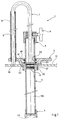
- la figure 1 est une vue en coupe verticale d'un appareil de prélèvement conforme à l'invention,
- les figures 2A, 2B et 2C sont des vues schématiques représentant conjointement le fonctionnement de l'appareil de la figure 1,
- les figures 3A et 3B sont des vues schématiques d'une variante de réalisation de l'appareil de la figure 1,
- la figure 4 est une vue de détail montrant la liaison temporaire des branches du U renversé des figures 3A et 3B,
- la figure 5 est une vue schématique partielle d'encore un autre appareil de prélèvement,
- la figure 6 est une vue schématique d'encore un autre appareil de prélèvement,
- la figure 7 est une vue partielle de l'appareil de la figure 6, selon la ligne de coupe VII-VII, et
- les figures 8A, 8B, et 8C sont des vues de dessus, de côté ou en coupe verticale d'un joint élastique à lèvres et la figure 8D est une vue avec coupe partielle de ce joint engagé dans un embout de tube plongeur.
- FIG. 1 is a view in vertical section of a sampling device according to the invention,
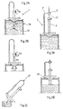
- FIGS. 2A, 2B and 2C are schematic views jointly representing the operation of the device of FIG. 1,
- FIGS. 3A and 3B are schematic views of an alternative embodiment of the device of FIG. 1,
- Figure 4 is a detail view showing the temporary connection of the branches of the inverted U of Figures 3A and 3B,
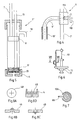
- FIG. 5 is a partial schematic view of yet another sampling device,
- FIG. 6 is a schematic view of yet another sampling device,
- FIG. 7 is a partial view of the apparatus of FIG. 6, along the section line VII-VII, and
- FIGS. 8A, 8B, and 8C are views from above, from the side or in vertical section of an elastic lip seal and FIG. 8D is a view with partial section of this seal engaged in a tip of a dip tube.
L'appareil de prélèvement représenté aux figures 1 et 2A à 2C sous la référence générale 1 comporte :
- une coupelle ou bague d'appui 2 destinée à porter sur le pourtour de l'orifice 52 d'un fût ou récipient 50 comportant une paroi sensiblement horizontale 51 ; cette coupelle est munie d'un
passage 2A muni intérieurement d'au moins un joint d'étanchéité 60 (ici doublé par un second joint d'étanchéité 61), - un corps
ou tube plongeur 3 adapté à coulisser de façon étanche dans lepassage 2A et muni en son extrémité inférieure d'un embout d'aspiration 4 ; de la sorte la bague 2 joue une fonction de raclage/nettoyage sur la surface extérieure dutube plongeur 3 ; comme cela apparaîtra plus loin le tube plongeur comporte en outre un trou de refoulement, ici constitué par letrou d'aspiration 4A de l'embout : letube 3 est fermé à sa partie supérieure parun bouchon percé 5 muni d'une vis de serrage 6, - un piston comportant, au bout d'une
tige 7,un disque 8 adapté à coulisser de manière étanche à l'intérieur dutube plongeur 3 et muni ici à cet effet de joints d'étanchéité, ici au nombre de deux et repérés 62et 63, - des moyens pour positionner en hauteur le disque 8 par rapport à la bague d'appui en sorte que ce disque reste à une distance donnée du niveau de la surface libre de la masse fluide 53 contenue dans le fût 50.
- a cup or
support ring 2 intended to bear on the periphery of theorifice 52 of a barrel orcontainer 50 having a substantiallyhorizontal wall 51; this cup is provided with apassage 2A provided internally with at least one seal 60 (here doubled by a second seal 61), - a body or
dip tube 3 adapted to slide in leaktight manner in thepassage 2A and provided at its lower end with asuction nozzle 4; in this way thering 2 plays a scraping / cleaning function on the outer surface of thedip tube 3; as will appear later the dip tube further comprises a delivery hole, here constituted by thesuction hole 4A of the end piece: thetube 3 is closed at its upper part by apierced plug 5 provided with a screw tightening 6, - a piston comprising, at the end of a
rod 7, adisc 8 adapted to slide in leaktight manner inside thedip tube 3 and provided here for this purpose with seals, here two in number and marked 62 and 63, - means for positioning the
disc 8 in height relative to the support ring so that this disc remains at a given distance from the level of the free surface of thefluid mass 53 contained in thebarrel 50.
Le passage 2A, le tube plongeur 3 et le disque 8 ont ici une section circulaire. Il est bien sûr possible de choisir, en variante, une section polygonale (carrée, rectangulaire, octogonale ou autre) pour des raisons par exemple de guidage.The
De manière préférée, la tige 7 du piston fait partie d'une pièce de conformation générale en U renversé, dont une branche est constituée par cette tige 7, et l'autre branche, repérée 9, comporte en son extrémité inférieure une portée d'appui 9A (ici sa tranche) adaptée à venir en appui sur une surface de référence, au moins temporairement liée à la bague d'appui 2.Preferably, the
Dans l'exemple des figures 1, 2A à 2C, les branches 7 et 9 font partie d'une seule et même pièce de sorte que la position du disque 8 est fixée une fois pour toutes vis-à-vis de la portée d'appui 9A ; de préférence ces branches ont des longueurs égales de sorte que le disque 8 est sensiblement au niveau de ladite tranche 9A ; en d'autres termes, le disque est sensiblement au niveau de la surface de référence.In the example of Figures 1, 2A to 2C, the
Dans l'exemple précité cette surface de référence est constituée par la paroi 51, à proximité immédiate de l'orifice 52.In the above example, this reference surface is constituted by the
Dans l'exemple des figures 1 à 2C, la bague 2 comporte avantageusement une oreille latérale à laquelle est fixé un manchon 10 pour le guidage en coulissement de la branche 9, à distance latérale du passage 2A.In the example of FIGS. 1 to 2C, the
En variante non représentée la surface de référence pourrait être directement solidaire de la bague 2 elle-même.In a variant not shown, the reference surface could be directly secured to the
En fonctionnement, conformément aux figures 2A à 2C, pour effectuer un prélèvement dans le fût 50 (par exemple de 200 litres), on saisit l'appareil 1 et on fait reposer la coupelle 2 au-dessus de l'ouverture 52 du fût 50. La partie en butée 9A de la branche 9 vient en appui sur le dessus 51 du fût immobilisant ainsi le disque 8. Après avoir dévissé la vis 6 du bouchon 5 (action A1), on introduit le corps 3 dans le fût en exerçant sur le corps 3 une poussée vers le bas (action A2) . Une chambre de remplissage 100, délimitée par le piston 8, le corps 3 et l'embout 4 fixé à l'extrémité du corps 3 plongeant dans le récipient, de volume initialement sensiblement nul, se remplit progressivement par du fluide aspiré au travers du trou 4A. Ce trou 4A a en principe une dimension de section inférieure à celle de la section intérieure du corps 3. Grâce à l'étanchéité de la chambre 100 du corps 3 assurée par les joints 62 et 63 (ici à section carrée) du disque 8, il se crée en effet une dépression à l'intérieur de la chambre 100 qui provoque une aspiration à travers du trou 4A des différents composants du fût au fur et à mesure de l'introduction du corps 3 et ceci jusqu'à la profondeur désirée, par exemple le fond du fût, réalisant ainsi un échantillonnage moyen précis (voir la figure 2A).In operation, in accordance with FIGS. 2A to 2C, to take a sample from the barrel 50 (for example 200 liters), the
A ce stade de l'opération, on a un carottage parfait du contenu du fût, lequel carottage est contenu dans la chambre 100 du corps 3 entre le piston 8 et l'embout 4.At this stage of the operation, there is a perfect coring of the contents of the barrel, which coring is contained in the
Afin d'immobiliser le disque 8 dans le tube plongeur 3, on serre la vis 6 sur le bouchon 5 (action A3) puis on extrait du fût le corps 3 en le faisant coulisser (action A4) à travers la coupelle 2 que l'on maintient en appui contre le fût. Le fait d'avoir immobilisé la tige 7 par rapport au bouchon 5 grâce à la vis 6 permet de remonter le corps 3 avec le disque 8, ceci ayant pour effet de conserver l'échantillon à l'intérieur de la chambre 100, le trou 4A de l'embout 4 étant calibré pour ne pas laisser s'échapper le produit (la calibration tenant compte de la viscosité du produit).In order to immobilize the
Il est à noter que lors de son extraction à travers la coupelle 2, le corps 3 est nettoyé extérieurement sur toute sa longueur grâce aux joints 60 et 61, de préférence à section carrée, placés dans la coupelle 2 au-passage du corps 3 (figure 2B).It should be noted that during its extraction through the
Il suffit maintenant de présenter l'orifice 4A au-dessus du flacon échantillon, de dévisser la vis 6 et de faire redescendre le disque 8, pour permettre de vider intégralement la chambre 100 du corps 3 (action A5 de la figure 2C).It now suffices to present the
Le disque ayant accompli toute sa course, l'appareil est propre aussi bien à l'intérieur qu'à l'extérieur, et est donc prêt pour un nouvel échantillonnage.As the disc has completed its travel, the device is clean both inside and out, and is therefore ready for re-sampling.
A titre d'exemple, la chambre 100 de remplissage a une capacité d'un demi-litre pour un prélèvement dans un fût d'une hauteur de 870 mm.By way of example, the filling
La capacité de cette chambre de prélèvement peut varier suivant l'échantillonnage à effectuer et le volume du récipient. Il suffit pour cela de modifier en conséquence les dimensions des différents éléments de l'appareil décrit ci-dessus à titre d'exemple non limitatif.The capacity of this sampling chamber may vary depending on the sampling to be carried out and the volume of the container. To do this, it suffices to modify the dimensions of the various elements of the apparatus described above by way of nonlimiting example.
Dans ce qui précède le fut 50 est supposé plein de sorte que le disque 8 est à peu près au niveau de sa surface libre.In the foregoing the
Dans le cas de prélèvement dans des fûts qui ne sont pas totalement remplis, l'air contenu dans la chambre 100 du corps 3 peut gêner l'absorption des produits épais. Il est alors recommandé de modifier la tige 7 afin de pouvoir positionner le piston 8 de manière à ce qu'il soit au niveau du produit absorbé.In the case of sampling from drums which are not completely filled, the air contained in the
Il est possible pour ce faire de modifier la pièce en U de la figure 1 en sorte que sa branche 7 soit plus longue que la branche 9.It is possible to do this to modify the U-shaped part of FIG. 1 so that its
En variante, ainsi que cela est représenté aux figures 3A, 3B et 4, cette pièce de conformation générale en U est formée de deux pièces distinctes : la tige 7' et une pièce 9' en J renversé dont les positions relatives en hauteur peuvent être ajustées grâce à un moyen de fixation temporaire 11 (les éléments similaires à ceux de la figure 1 sont les mêmes à part l'addition de l'indice "prime").As a variant, as shown in FIGS. 3A, 3B and 4, this part of general U-shaped configuration is formed by two distinct parts: the
Cet élément de fixation temporaire est ici formé d'un manchon 11A solidaire de la branche 9' adapté à recevoir la tige 7' en coulissement et muni d'une vis de serrage 11B.This temporary fixing element is here formed of a
Le disque 8 et l'extrémité de la partie 9A' en butée, présentent une différence de niveau qui peut être modifiée grâce au moyen de fixation 11 (la figure 3A correspond à un fût plein tandis que la figure 3B correspond à un fût incomplètement rempli).The
On peut également prévoir un dispositif de blocage de la coupelle 2 de manière à la solidariser et, ou de l'étancher par rapport au fût. Par exemple, il est possible d'exécuter un filetage sur l'extérieur de la partie inférieure de la coupelle (par exemple la jupe 2B de la figure 1), lequel filetage permet de visser la coupelle sur tous les fûts équipés d'une ouverture avec filetage.One can also provide a locking device for the
On peut aussi rajouter un deuxième disque de piston 12 sous le disque de piston 8 avec une autre tige 13. Le disque de piston 12 est alors avantageusement muni d'une soupape schématisée en 20 permettant uniquement le passage du fluide dans un sens vers le haut après la phase de remplissage du corps 3 comme défini précédemment. Il suffit de remonter le disque 12 à l'aide de la tige 13 pour, à travers un embout 30 ménagé dans la paroi du tube 3 à proximité de son extrémité supérieure, prélever directement l'échantillon dans un flacon éprouvette. Il faut ensuite redescendre les disques 8 et 12 de manière à refouler les produits qui auraient été absorbés dans la chambre lors de la remontée du disque 12.It is also possible to add a
Cet embout 30 reste séparé de l'embout d'aspiration 4 par le disque 8 sur une partie seulement de la course de coulissement relatif entre ce disque et le tube. Il est recommandé en pratique que cet embout ne soit dégagé par le disque 8 qu'à la fin de sa course ascendante.This
Cet appareil repéré 1'' à la figure 5 peut se révéler très pratique lorsque l'espace dans lequel évolue l'opérateur est exigu. En effet, l'échantillon se recueille directement à la sortie de l'orifice 30 et ceci alors que l'appareil est toujours plongé dans le fût. Cependant il ne s'avère efficace que lorsque les produits à échantillonner sont de la même famille et les fûts totalement pleins, puisque l'intérieur de l'embout 30 se nettoie difficilement. De plus le réglage de la distance entre le piston 8 et la butée 9A de l'autre branche 9 (comme défini précédemment) n'est plus possible si l'on veut conserver l'orifice 30 d'écoulement en dehors du fût.This device, identified 1 '' in Figure 5, can be very practical when the space in which the operator operates is confined. Indeed, the sample is collected directly at the outlet of the
Le disque 12 peut éventuellement remplacer l'embout 4.The
Afin de faciliter le réglage relatif de la butée d'appui 9A et du disque 8 comme défini ci-dessus, on peut adjoindre à l'appareil (par exemple au tube 3) un détecteur de niveau non représenté qui grâce par exemple à un contact, un flotteur ou tout autre procédé de signalisation, indique à l'opérateur le moment précis ou l'extrémité trouée de l'embout 4 vient en contact avec la surface du liquide contenu dans le récipient.In order to facilitate the relative adjustment of the
Pour faciliter les opérations, on peut aussi rajouter à l'appareil un vérin pneumatique de section suffisamment importante ou tout autre dispositif (schématisé en 40 à la figure 6) pour déplacer le corps 3 et lui permettre de parcourir la course nécessaire au remplissage et au vidage de la chambre 100.To facilitate the operations, it is also possible to add to the device a pneumatic cylinder of sufficiently large section or any other device (shown diagrammatically at 40 in FIG. 6) to move the
Si le calibrage du trou 4A du bouchon 4 ne permet pas de maintenir les liquides à l'intérieur du tube 3, on peut disposer dans ce bouchon un joint à lèvres (figure 8D) dont les lèvres sont orientées vers l'intérieur du tube (figure 8B) ou vers l'extérieur (figure 8C) suivant que l'on vient d'aspirer ou de refouler du fluide. Ce joint ne permettra l'écoulement que lorsqu'on appliquera une pression sur le disque 8.If the calibration of the
Si le refoulement doit se faire au travers du même trou, la partie mobile du clapet comporte avantageusement une saillie non représentée accessible de l'extérieur pour forcer l'ouverture, soit manuellement, soit par butée sur une surface d'appui du flacon éprouvette où l'on veut verser le contenu de la chambre 100.If the discharge must be done through the same hole, the movable part of the valve advantageously includes a projection (not shown) accessible from the outside. to force the opening, either manually or by abutment on a bearing surface of the test vial where one wants to pour the contents of the
Pour faciliter la manipulation de la tige 7 par l'intermédiaire de la branche 9 on peut prévoir une saignée longitudinale 10A sur le manchon 10 et fixer un élément de manutention tel qu'une poignée 9B sur la tige 9.To facilitate the manipulation of the
On peut prévoir des capuchons en plastique pour protéger la surface de l'extrémité de l'embout 4, lesquels capuchons seront jetés entre deux prélèvements, ceci pour remédier au problème de nettoyage de l'extrémité dudit embout 4.Plastic caps can be provided to protect the surface of the end of the
La coupelle peut comporter inférieurement plusieurs gradins annulaires de centrage 71 et 72 grâce auxquels elle peut s'adapter à plusieurs diamètres d'orifice.The cup can have several annular centering
Claims (20)
- Device for taking samples of fluid from a drum filled with a mass of fluid up to a given level and having a substantially horizontal wall (51) provided with a filler orifice (52), including:- a dip-tube (3) having a closure member (4),- a piston including at the end of a piston rod (7) a disc (8) adapted to slide in the dip-tube, to which it sealed, and- means (7 + 9 + 9A; 11) for temporarily positioning the piston disc in the heightwise direction so that this disc remains at a given distance from the surface of the fluid mass,characterised in that it includes a support ring (2) adapted to rest on the surround of the filler orifice (52) and having a passage (2A) having on the inside at least one scraper seal in which the dip-tube is adapted to slide, and to which it is sealed, in that relative movement between the piston and the dip-tube is such that the disc remains at all times in the dip-tube, and in that the closure member is formed as an end-piece (4) in which is a hole (4A) provided with non-return means enabling fluid to be aspirated into the tube but preventing fluid escaping therefrom under its own weight.
- Sampling device according to claim 1 characterised in that the piston rod is part of a generally inverted U-shaped member of which one branch (7, 7') is constituted by the rod and another branch (9, 9') has at its lower end a bearing surface (9A) adapted to bear on a reference surface (51) for the support ring, these branches being linked by these positioning means.
- Sampling device according to claim 2 characterised in that this bearing surface is adapted to bear on said wall (51) of the drum.
- Sampling device according to claim 3 characterised in that said other branch is adapted to slide in a guide sleeve (10) attached to the support ring at a distance from said passage.
- Sampling device according to claim 4 characterised in that the sleeve includes a longitudinal slot (10A) and said other branch includes holding means (9B) projecting radially from the sleeve through said slot.
- Sampling device according to claim 2 characterised in that the reference surface is linked to the support ring.
- Sampling device according to any one of claims 2 to 6 characterised in that the two branches of the U-shaped member are fastened together.
- Sampling device according to any one of claims 2 to 6 characterised in that the two branches of the U-shaped member are provided with means (11) for adjusting their relative position.
- Sampling device according to claim 8 characterised in that said other branch includes at its upper end a sleeve (11A) adapted to receive the piston rod which slides in it and provided with clamping means (11B).
- Sampling device according to any one of claims 1 to 9 characterised in that the support ring has on its lower face at least two annular centring steps (71, 72) matching at least two filler orifice diameters.
- Sampling device according to any one of claims 1 to 10 characterised in that the support ring includes an externally screwthreaded skirt (2B).
- Sampling device according to any one of claims 1 to 11 characterised in that the dip-tube and the piston rod are provided with temporary fixing means (5, 6).
- Sampling device according to any one of claims 1 to 12 characterised in that the end-piece (4) includes a hole (4A) constituting an aspiration hole and a discharge hole.
- Sampling device according to claim 13 characterised in that said hole has a diameter chosen according to the viscosity of the fluid mass to enable aspiration and discharge of the sample by relative disc/tube movement whilst preventing the sample escaping under its own weight.
- Sampling device according to claim 13 characterised in that said hole is formed in a split elastic seal and is flanked by one or more lips.
- Sampling device according to claim 13 characterised in that the hole is closed by an anti-leak valve incorporating an opening member accessible from the outside.
- Sampling device according to any one of claims 1 to 12 characterised in that it includes a discharge hole (30) in the wall of the tube (3) near its upper end so that it is separated from the end-piece (4) by the disc (8) over part only of the relative sliding travel between the disc (8) and the tube, a second piston disc (12) provided with a non-return valve being provided in the tube under the disc (8) to force discharge of the fluid sample by upward movement.
- Sampling device according to claim 17 characterised in that the second disc (12) constitutes the end-piece (4).
- Method of taking a sample of fluid from a drum filled with a mass of fluid up to a given level whereby a dip-tube is immersed in the fluid mass which has at its lower end an entry orifice, by sliding the tube around a disc to which it is sealed with the distance between the disc and the surface of the fluid mass kept constant, the dip-tube is removed from the fluid mass with the disc held in a fixed position relative to the tube, and the content of the tube between the end-piece and the disc is expelled through a discharge hole,
characterised in that the disc remains inside the tube at all times, the fluid is caused to enter the tube during the immersion movement by forced aspiration through a closure member including an orifice provided with non-return means preventing escape of the fluid under its own weight, and the dip-tube slides inside a scraper ring fixed at least temporarily to the disc. - Sampling method according to claim 19 characterised in that in use the disc is positioned substantially level with the surface of the fluid mass.
Applications Claiming Priority (2)
| Application Number | Priority Date | Filing Date | Title |
|---|---|---|---|
| FR9409898 | 1994-08-10 | ||
| FR9409898A FR2723639B1 (en) | 1994-08-10 | 1994-08-10 | APPARATUS AND METHOD FOR COLLECTING IN BOTTOM OR CONTAINER OF LIQUID SAMPLES OF DIFFERENT VISCOSITIES. |
Publications (2)
| Publication Number | Publication Date |
|---|---|
| EP0697589A1 EP0697589A1 (en) | 1996-02-21 |
| EP0697589B1 true EP0697589B1 (en) | 1997-04-16 |
Family
ID=9466224
Family Applications (1)
| Application Number | Title | Priority Date | Filing Date |
|---|---|---|---|
| EP95401872A Expired - Lifetime EP0697589B1 (en) | 1994-08-10 | 1995-08-09 | Apparatus and method for taking samples of liquids of different viscosities from a barrel |
Country Status (5)
| Country | Link |
|---|---|
| US (1) | US5663511A (en) |
| EP (1) | EP0697589B1 (en) |
| AT (1) | ATE151876T1 (en) |
| DE (1) | DE69500240T2 (en) |
| FR (1) | FR2723639B1 (en) |
Families Citing this family (12)
| Publication number | Priority date | Publication date | Assignee | Title |
|---|---|---|---|---|
| US5749174A (en) * | 1996-03-11 | 1998-05-12 | Excel Industries, Inc. | Window regulator with spring retainer |
| US5901240A (en) * | 1996-12-12 | 1999-05-04 | Eastman Kodak Company | Method for detecting the collimation field in a digital radiography |
| US6258324B1 (en) | 1999-03-15 | 2001-07-10 | Felix H. Yiu | Pipette dispensing block |
| CN104132825A (en) * | 2014-08-14 | 2014-11-05 | 长兴宏能电热膜元件厂 | Piston mechanism of electrothermal film solution sampling container |
| CN104132826A (en) * | 2014-08-14 | 2014-11-05 | 长兴宏能电热膜元件厂 | Electrothermal film solution sampling container |
| CN104122114A (en) * | 2014-08-14 | 2014-10-29 | 长兴宏能电热膜元件厂 | Improved structure of electrothermal film solution sampling container |
| CN104122115A (en) * | 2014-08-14 | 2014-10-29 | 长兴宏能电热膜元件厂 | Liquid inlet structure of electrothermal film solution sampling bucket |
| WO2017066565A1 (en) * | 2015-10-14 | 2017-04-20 | York Laboratories, LLC | Grease sampling device and related method |
| CN106996892A (en) * | 2017-03-28 | 2017-08-01 | 四川出入境检验检疫局检验检疫技术中心 | Food contact sheet material specific transfer experiment sampling infuser device |
| RU2696448C1 (en) * | 2019-03-15 | 2019-08-01 | Общество с ограниченной ответственностью "Научно-производственное объединение Машиностроения "Сварог" | Stationary sampling system with measurement hatch |
| CN112485066B (en) * | 2020-12-27 | 2022-09-27 | 刘秀英 | Medical science inspection liquid multitube difference sampling device |
| CN112985915B (en) * | 2021-04-02 | 2022-06-07 | 安徽国泰众信检测技术有限公司 | Milk system food device for sample |
Family Cites Families (12)
| Publication number | Priority date | Publication date | Assignee | Title |
|---|---|---|---|---|
| US1950854A (en) * | 1930-03-28 | 1934-03-13 | Lerch William Bruce | Liquid sampler and method for sampling liquids |
| FR718955A (en) * | 1931-06-22 | 1932-01-30 | Soc Fr Constr Babcock & Wilcox | closed-loop sampler |
| US2255369A (en) * | 1939-09-28 | 1941-09-09 | Spaeth Charles | Sampling device for liquid storage systems |
| DE824569C (en) * | 1949-02-26 | 1951-12-13 | Louis Scheible | Milk meter |
| US3115782A (en) * | 1961-04-04 | 1963-12-31 | Consolidation Coal Co | Sampling apparatus |
| US3277723A (en) * | 1964-05-08 | 1966-10-11 | Ralph H Bodman | Fluid sampler |
| FR2423767A1 (en) * | 1978-04-20 | 1979-11-16 | Pipeline Service Sa | METHOD AND DEVICE FOR TAKING A SAMPLE OF LIQUID IN A STORAGE TANK |
| US4318885A (en) * | 1979-09-10 | 1982-03-09 | Olympus Optical Co., Ltd. | Liquid treating device for chemical analysis apparatus |
| US4612815A (en) * | 1985-02-14 | 1986-09-23 | Green Dennis A | Method and apparatus for sampling hazardous material |
| US5139654A (en) * | 1990-10-22 | 1992-08-18 | Norton Company | Liquid collector pressurizing and filtering means |
| DE4211633A1 (en) * | 1992-03-30 | 1993-10-07 | Andreas Dipl Ing Kaiser | Liquid sampling system esp. for dirty water - consists of swivelable closing plate rotated by spring-loaded rod at lower end face of tube which contains piston. |
| FR2700851B1 (en) * | 1993-01-26 | 1995-04-14 | Sgn Soc Gen Tech Nouvelle | Device and method for taking samples of a material. |
-
1994
- 1994-08-10 FR FR9409898A patent/FR2723639B1/en not_active Expired - Fee Related
-
1995
- 1995-08-08 US US08/512,573 patent/US5663511A/en not_active Expired - Fee Related
- 1995-08-09 DE DE69500240T patent/DE69500240T2/en not_active Expired - Fee Related
- 1995-08-09 EP EP95401872A patent/EP0697589B1/en not_active Expired - Lifetime
- 1995-08-09 AT AT95401872T patent/ATE151876T1/en not_active IP Right Cessation
Also Published As
| Publication number | Publication date |
|---|---|
| EP0697589A1 (en) | 1996-02-21 |
| ATE151876T1 (en) | 1997-05-15 |
| FR2723639A1 (en) | 1996-02-16 |
| US5663511A (en) | 1997-09-02 |
| DE69500240D1 (en) | 1997-05-22 |
| FR2723639B1 (en) | 1996-11-08 |
| DE69500240T2 (en) | 1997-08-14 |
Similar Documents
| Publication | Publication Date | Title |
|---|---|---|
| EP0697589B1 (en) | Apparatus and method for taking samples of liquids of different viscosities from a barrel | |
| EP1385411B1 (en) | Device for compacting waste in a vacuum cleaner | |
| EP3227658B1 (en) | Method and device for withdrawing a sample from a liquid | |
| EP0803723B1 (en) | Device for taking noxious liquidsampler, in particular loaded with solid particulates | |
| FR2884225A1 (en) | FILLING METHOD AND DEVICE FOR FILLING A VARIABLE USEFUL VOLUME TANK | |
| EP0506534B1 (en) | Liquid sampling head | |
| WO2011054850A1 (en) | Filling device having a special valve system | |
| EP3000319B1 (en) | Device for transferring a liquid from a container to a vessel in a sealed manner | |
| EP0063971B1 (en) | Device for taking liquid samples | |
| FR2950608A1 (en) | Filling device for rotary type filling machine to fill container e.g. bottles, with food product, has tubular body whose lower part is mounted on upper part of body by quick action coupling system with blocking unit | |
| EP0296917B1 (en) | Device for continuously circulating a liquid in order to sample or to check this liquid | |
| EP0214903A1 (en) | Automatic sampling apparatus | |
| FR3025186A1 (en) | CONTAINER FOR VISCOUS LIQUID COMPRISING A CAP COMPRISING A FAUCET | |
| EP1893123A1 (en) | Method for packing a predetermined liquid substance dose in a straw and device for carrying out said method | |
| WO2000055087A1 (en) | Filling spout | |
| FR2474328A1 (en) | Sepn. tank for immiscible liquids with different densities - used esp. for continuous sepn. of oil from waste water, where water outlet can be closed for periodic removal of oil | |
| WO2002024524A1 (en) | Device for filling liquid with automatic closure | |
| FR2677633A1 (en) | Oil change funnel for combustion engines and its adaptation accessory for service station | |
| EP0730142A1 (en) | Device for taking liquid samples | |
| BE472324A (en) | ||
| FR2540088A1 (en) | Device for filling containers | |
| FR2662151A1 (en) | Draining spanner (wrench) | |
| BE570763A (en) | ||
| BE677349A (en) | ||
| FR2636137A1 (en) | Device for taking samples of liquid products |
Legal Events
| Date | Code | Title | Description |
|---|---|---|---|
| PUAI | Public reference made under article 153(3) epc to a published international application that has entered the european phase |
Free format text: ORIGINAL CODE: 0009012 |
|
| AK | Designated contracting states |
Kind code of ref document: A1 Designated state(s): AT BE CH DE DK ES FR GB GR IE IT LI LU MC NL PT SE |
|
| 17P | Request for examination filed |
Effective date: 19960330 |
|
| GRAG | Despatch of communication of intention to grant |
Free format text: ORIGINAL CODE: EPIDOS AGRA |
|
| 17Q | First examination report despatched |
Effective date: 19960805 |
|
| GRAH | Despatch of communication of intention to grant a patent |
Free format text: ORIGINAL CODE: EPIDOS IGRA |
|
| GRAH | Despatch of communication of intention to grant a patent |
Free format text: ORIGINAL CODE: EPIDOS IGRA |
|
| GRAA | (expected) grant |
Free format text: ORIGINAL CODE: 0009210 |
|
| AK | Designated contracting states |
Kind code of ref document: B1 Designated state(s): AT BE CH DE DK ES FR GB GR IE IT LI LU MC NL PT SE |
|
| PG25 | Lapsed in a contracting state [announced via postgrant information from national office to epo] |
Ref country code: NL Effective date: 19970416 Ref country code: IT Free format text: LAPSE BECAUSE OF FAILURE TO SUBMIT A TRANSLATION OF THE DESCRIPTION OR TO PAY THE FEE WITHIN THE PRE;WARNING: LAPSES OF ITALIAN PATENTS WITH EFFECTIVE DATE BEFORE 2007 MAY HAVE OCCURRED AT ANY TIME BEFORE 2007. THE CORRECT EFFECTIVE DATE MAY BE DIFFERENT FROM THE ONE RECORDED.SCRIBED TIME-LIMIT Effective date: 19970416 Ref country code: GR Free format text: LAPSE BECAUSE OF FAILURE TO SUBMIT A TRANSLATION OF THE DESCRIPTION OR TO PAY THE FEE WITHIN THE PRESCRIBED TIME-LIMIT Effective date: 19970416 Ref country code: ES Free format text: THE PATENT HAS BEEN ANNULLED BY A DECISION OF A NATIONAL AUTHORITY Effective date: 19970416 Ref country code: DK Effective date: 19970416 |
|
| REF | Corresponds to: |
Ref document number: 151876 Country of ref document: AT Date of ref document: 19970515 Kind code of ref document: T |
|
| REG | Reference to a national code |
Ref country code: CH Ref legal event code: EP |
|
| GBT | Gb: translation of ep patent filed (gb section 77(6)(a)/1977) |
Effective date: 19970417 |
|
| REF | Corresponds to: |
Ref document number: 69500240 Country of ref document: DE Date of ref document: 19970522 |
|
| PG25 | Lapsed in a contracting state [announced via postgrant information from national office to epo] |
Ref country code: SE Effective date: 19970716 Ref country code: PT Effective date: 19970716 |
|
| REG | Reference to a national code |
Ref country code: IE Ref legal event code: FG4D Free format text: 73409 |
|
| PG25 | Lapsed in a contracting state [announced via postgrant information from national office to epo] |
Ref country code: LU Free format text: LAPSE BECAUSE OF NON-PAYMENT OF DUE FEES Effective date: 19970809 |
|
| NLV1 | Nl: lapsed or annulled due to failure to fulfill the requirements of art. 29p and 29m of the patents act | ||
| PLBE | No opposition filed within time limit |
Free format text: ORIGINAL CODE: 0009261 |
|
| STAA | Information on the status of an ep patent application or granted ep patent |
Free format text: STATUS: NO OPPOSITION FILED WITHIN TIME LIMIT |
|
| PG25 | Lapsed in a contracting state [announced via postgrant information from national office to epo] |
Ref country code: MC Free format text: LAPSE BECAUSE OF NON-PAYMENT OF DUE FEES Effective date: 19980228 |
|
| 26N | No opposition filed | ||
| REG | Reference to a national code |
Ref country code: IE Ref legal event code: FD4D Ref document number: 73409 Country of ref document: IE |
|
| PG25 | Lapsed in a contracting state [announced via postgrant information from national office to epo] |
Ref country code: LI Free format text: LAPSE BECAUSE OF NON-PAYMENT OF DUE FEES Effective date: 19980831 Ref country code: CH Free format text: LAPSE BECAUSE OF NON-PAYMENT OF DUE FEES Effective date: 19980831 |
|
| REG | Reference to a national code |
Ref country code: CH Ref legal event code: PL |
|
| PGFP | Annual fee paid to national office [announced via postgrant information from national office to epo] |
Ref country code: FR Payment date: 20010731 Year of fee payment: 7 |
|
| PGFP | Annual fee paid to national office [announced via postgrant information from national office to epo] |
Ref country code: GB Payment date: 20010810 Year of fee payment: 7 |
|
| PGFP | Annual fee paid to national office [announced via postgrant information from national office to epo] |
Ref country code: DE Payment date: 20010816 Year of fee payment: 7 |
|
| PGFP | Annual fee paid to national office [announced via postgrant information from national office to epo] |
Ref country code: AT Payment date: 20010821 Year of fee payment: 7 |
|
| PGFP | Annual fee paid to national office [announced via postgrant information from national office to epo] |
Ref country code: BE Payment date: 20010907 Year of fee payment: 7 |
|
| REG | Reference to a national code |
Ref country code: GB Ref legal event code: IF02 |
|
| PG25 | Lapsed in a contracting state [announced via postgrant information from national office to epo] |
Ref country code: GB Free format text: LAPSE BECAUSE OF NON-PAYMENT OF DUE FEES Effective date: 20020809 Ref country code: AT Free format text: LAPSE BECAUSE OF NON-PAYMENT OF DUE FEES Effective date: 20020809 |
|
| PG25 | Lapsed in a contracting state [announced via postgrant information from national office to epo] |
Ref country code: BE Free format text: LAPSE BECAUSE OF NON-PAYMENT OF DUE FEES Effective date: 20020831 |
|
| BERE | Be: lapsed |
Owner name: *HOUILLERES DU BASSIN DE LORRAINE Effective date: 20020831 |
|
| PG25 | Lapsed in a contracting state [announced via postgrant information from national office to epo] |
Ref country code: DE Free format text: LAPSE BECAUSE OF NON-PAYMENT OF DUE FEES Effective date: 20030301 |
|
| GBPC | Gb: european patent ceased through non-payment of renewal fee |
Effective date: 20020809 |
|
| PG25 | Lapsed in a contracting state [announced via postgrant information from national office to epo] |
Ref country code: FR Free format text: LAPSE BECAUSE OF NON-PAYMENT OF DUE FEES Effective date: 20030430 |
|
| REG | Reference to a national code |
Ref country code: FR Ref legal event code: ST |