EP0697589B1 - Vorrichtung und Verfahren zur Probenahme von Flüssigkeiten unterschiedlicher Viskositäten aus einem Fass - Google Patents
Vorrichtung und Verfahren zur Probenahme von Flüssigkeiten unterschiedlicher Viskositäten aus einem Fass Download PDFInfo
- Publication number
- EP0697589B1 EP0697589B1 EP95401872A EP95401872A EP0697589B1 EP 0697589 B1 EP0697589 B1 EP 0697589B1 EP 95401872 A EP95401872 A EP 95401872A EP 95401872 A EP95401872 A EP 95401872A EP 0697589 B1 EP0697589 B1 EP 0697589B1
- Authority
- EP
- European Patent Office
- Prior art keywords
- tube
- disc
- sampling device
- fluid
- dip
- Prior art date
- Legal status (The legal status is an assumption and is not a legal conclusion. Google has not performed a legal analysis and makes no representation as to the accuracy of the status listed.)
- Expired - Lifetime
Links
- 238000000034 method Methods 0.000 title claims description 11
- 239000007788 liquid Substances 0.000 title description 6
- 239000012530 fluid Substances 0.000 claims description 42
- 238000005070 sampling Methods 0.000 claims description 38
- 239000000945 filler Substances 0.000 claims 3
- 238000007654 immersion Methods 0.000 claims 1
- 230000005484 gravity Effects 0.000 description 4
- 238000004140 cleaning Methods 0.000 description 3
- 230000000694 effects Effects 0.000 description 2
- 229940082150 encore Drugs 0.000 description 2
- 235000020004 porter Nutrition 0.000 description 2
- 238000007790 scraping Methods 0.000 description 2
- 230000003068 static effect Effects 0.000 description 2
- 239000000126 substance Substances 0.000 description 2
- 208000031968 Cadaver Diseases 0.000 description 1
- 240000008042 Zea mays Species 0.000 description 1
- 238000010521 absorption reaction Methods 0.000 description 1
- 239000000470 constituent Substances 0.000 description 1
- 230000002089 crippling effect Effects 0.000 description 1
- 238000006073 displacement reaction Methods 0.000 description 1
- 235000021183 entrée Nutrition 0.000 description 1
- 238000000605 extraction Methods 0.000 description 1
- 229930195733 hydrocarbon Natural products 0.000 description 1
- 150000002430 hydrocarbons Chemical class 0.000 description 1
- 230000003100 immobilizing effect Effects 0.000 description 1
- 239000004615 ingredient Substances 0.000 description 1
- 238000003780 insertion Methods 0.000 description 1
- 230000037431 insertion Effects 0.000 description 1
- 239000010808 liquid waste Substances 0.000 description 1
- 239000000463 material Substances 0.000 description 1
- 239000002184 metal Substances 0.000 description 1
- 239000003921 oil Substances 0.000 description 1
- 235000011837 pasties Nutrition 0.000 description 1
- 230000002093 peripheral effect Effects 0.000 description 1
- 238000007789 sealing Methods 0.000 description 1
- 230000011664 signaling Effects 0.000 description 1
- 239000000725 suspension Substances 0.000 description 1
Images
Classifications
-
- G—PHYSICS
- G01—MEASURING; TESTING
- G01N—INVESTIGATING OR ANALYSING MATERIALS BY DETERMINING THEIR CHEMICAL OR PHYSICAL PROPERTIES
- G01N1/00—Sampling; Preparing specimens for investigation
- G01N1/02—Devices for withdrawing samples
- G01N1/10—Devices for withdrawing samples in the liquid or fluent state
- G01N1/12—Dippers; Dredgers
-
- G—PHYSICS
- G01—MEASURING; TESTING
- G01N—INVESTIGATING OR ANALYSING MATERIALS BY DETERMINING THEIR CHEMICAL OR PHYSICAL PROPERTIES
- G01N1/00—Sampling; Preparing specimens for investigation
- G01N1/02—Devices for withdrawing samples
- G01N1/10—Devices for withdrawing samples in the liquid or fluent state
- G01N2001/1031—Sampling from special places
- G01N2001/1037—Sampling from special places from an enclosure (hazardous waste, radioactive)
Definitions
- Document DE-A-4,211,633 discloses a sampling device comprising a piston formed by a disc and a rod, and a dip tube in which the disc can slide in leaktight manner.
- a vertical rod On the side of the dip tube is mounted a vertical rod at the base of which is fixed a peripheral portion of a suitable sealing disc, depending on the angular position of the rod around its longitudinal axis, to release or seal the lower end of the dip tube.
- the enclosure has no upper wall.
- the piston rod (and therefore the piston disc) is positioned relative to the enclosure (by simple suspension it seems); one controls, by rotation of the rod, a lateral release of the shutter disc and the dip tube is lowered to the bottom of the barrel; the shutter disc is brought back to the shutter configuration.
- Document US-A-3.115.782 relates to the taking of samples in a flow. It proposes a device comprising, arranged transversely to a flow pipe, a tube and a piston rod provided with at least two piston disks, one of which is a terminal disk.
- the tube is mounted in a retaining ring removably attached to a transverse section of the conduit; the tube slides tightly in the ring and the discs are adapted to slide tightly in the tube.
- the rod is moved over the entire section of the conduit until the end disc comes into abutment against the internal wall opposite the transverse conduit.
- the flow is allowed to stabilize and then the tube is slide in the same way so as to trap a sample in the tube (or several samples if there are more than two discs).
- this sampler does not allow any adjustment in height of the sampling. As the sample comes above the terminal disc and around the rod, these are soiled during each sampling.
- the invention proposes to remedy all these drawbacks by means of a suction and forcing function of fluid in a vacuum chamber enabling samples to be taken quickly and simply from drums or any other container at an advantageously variable level, their fluid content, for example static, whether liquid or pasty, while respecting the proportions of the various constituents and thanks to scraping and cleaning functions of the parts in contact with the fluids, making it possible to carry out successive samplings of various and varied products without significant pollution of the barrels or bottles of samples between them.
- the invention also provides a method of taking a fluid sample from a barrel filled with a fluid mass up to a given level, according to which a dip tube is provided in this fluid mass provided at its lower end with an orifice entry by sliding this tube, sealingly, around a disc whose distance to the free surface of this fluid mass is kept constant, the tube is removed from the fluid mass by maintaining the disc in a fixed position vis-à-vis this tube, and the contents of the tube situated between the end piece and the disc are expelled through a delivery hole, characterized in that the disc is permanently maintained inside the tube, fluid is introduced into the tube, during the plunging movement, by forced suction through a closure element comprising an orifice provided with 'a non-return means preventing the escape of fluid by simple gravity, and the dip tube is made to slide inside a scraper ring fixed at least temporarily with respect to this disc.
- the disk is positioned substantially at the level of the free surface of this fluid mass.
- the passage 2A, the dip tube 3 and the disc 8 have here a circular section. It is of course possible to choose, as a variant, a polygonal section (square, rectangular, octagonal or other) for reasons of guidance, for example.
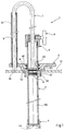
- the rod 7 of the piston is part of a general conformation part in an inverted U, one branch of which is constituted by this rod 7, and the other branch, marked 9, has a bearing surface at its lower end.
- support 9A (here its edge) adapted to come to bear on a reference surface, at least temporarily linked to the support ring 2.
- the branches 7 and 9 are part of a single piece so that the position of the disc 8 is fixed once and for all with respect to the scope of support 9A; preferably these branches have equal lengths so that the disc 8 is substantially at the level of said edge 9A; in other words, the disc is substantially at the level of the reference surface.
- this reference surface is constituted by the wall 51, in the immediate vicinity of the orifice 52.
- the ring 2 advantageously comprises a lateral lug to which is fixed a sleeve 10 for the sliding guide of the branch 9, at a lateral distance from the passage 2A.
- the reference surface could be directly secured to the ring 2 itself.
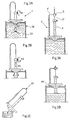
- This hole 4A has in principle a cross-section dimension smaller than that of the internal section of the body 3. Thanks to the tightness of the chamber 100 of the body 3 provided by the seals 62 and 63 (here with square section) of the disc 8, a vacuum is created inside the chamber 100 which causes suction through the hole 4A of the various components of the barrel as the body 3 is introduced and this to the desired depth, for example the bottom of the barrel, thus carrying out a precise average sampling (see Figure 2A).
- the body 3 is cleaned externally over its entire length thanks to the seals 60 and 61, preferably of square section, placed in the cup 2 at the passage of the body 3 ( Figure 2B).
- the device As the disc has completed its travel, the device is clean both inside and out, and is therefore ready for re-sampling.
- the filling chamber 100 has a capacity of half a liter for sampling from a barrel 870 mm high.
- This sampling chamber may vary depending on the sampling to be carried out and the volume of the container. To do this, it suffices to modify the dimensions of the various elements of the apparatus described above by way of nonlimiting example.
- the barrel 50 is assumed to be full so that the disc 8 is approximately at the level of its free surface.
- the air contained in the chamber 100 of the body 3 can hinder the absorption of thick products. It is then recommended to modify the rod 7 so as to be able to position the piston 8 so that it is at the level of the absorbed product.
- this part of general U-shaped configuration is formed by two distinct parts: the rod 7 ′ and a part 9 ′ in inverted J whose relative positions in height can be adjusted by means of a temporary fixing means 11 (the elements similar to those of FIG. 1 are the same except for the addition of the "prime" index).
- This temporary fixing element is here formed of a sleeve 11A integral with the branch 9 'adapted to receive the rod 7' sliding and provided with a clamping screw 11B.
- FIG. 3A corresponds to a full barrel while FIG. 3B corresponds to an incompletely filled barrel ).
- a locking device for the cup 2 so as to secure it and, or to seal it with respect to the barrel.
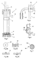
- piston disc 12 under the piston disc 8 with another rod 13.
- the piston disc 12 is then advantageously provided with a valve shown diagrammatically by allowing only the passage of the fluid in an upward direction. after the body filling phase 3 as defined above. It suffices to reassemble the disc 12 using the rod 13 to, through a nozzle 30 formed in the wall of the tube 3 near its upper end, take the sample directly in a test vial. The discs 8 and 12 must then be lowered so as to push back the products which would have been absorbed in the chamber during the ascent of the disc 12.
- This end piece 30 remains separated from the suction end piece 4 by the disc 8 over only part of the relative sliding stroke between this disc and the tube. It is recommended in practice that this tip is not released by the disc 8 until the end of its upward stroke.
- This device can be very practical when the space in which the operator operates is confined. Indeed, the sample is collected directly at the outlet of the orifice 30 and this while the apparatus is still immersed in the barrel. However, it only proves effective when the products to be sampled are from the same family and the drums are completely full, since the inside of the nozzle 30 is difficult to clean. In addition, the adjustment of the distance between the piston 8 and the stop 9A of the other branch 9 (as defined above) is no longer possible if one wishes to keep the flow orifice 30 outside the barrel.
- the disc 12 can optionally replace the end piece 4.
- a level detector not shown which, for example thanks to a contact , a float or any other signaling method, indicates to the operator the precise moment when the perforated end of the nozzle 4 comes into contact with the surface of the liquid contained in the container.
- a pneumatic cylinder of sufficiently large section or any other device shown diagrammatically at 40 in FIG. 6) to move the body 3 and allow it to travel the stroke necessary for filling and emptying of chamber 100.
- a lip seal can be placed in this stopper (FIG. 8D) whose lips are oriented towards the inside of the tube ( Figure 8B) or outward ( Figure 8C) depending on whether one has just sucked or discharged fluid. This seal will only allow flow when pressure is applied to the disc 8.
- the movable part of the valve advantageously includes a projection (not shown) accessible from the outside. to force the opening, either manually or by abutment on a bearing surface of the test vial where one wants to pour the contents of the chamber 100.
- Plastic caps can be provided to protect the surface of the end of the tip 4, which caps will be discarded between two samples, this to remedy the problem of cleaning the end of said tip 4.
- the cup can have several annular centering steps 71 and 72 below which allow it to adapt to several orifice diameters.
Landscapes
- Life Sciences & Earth Sciences (AREA)
- Hydrology & Water Resources (AREA)
- Physics & Mathematics (AREA)
- Health & Medical Sciences (AREA)
- Chemical & Material Sciences (AREA)
- Analytical Chemistry (AREA)
- Biochemistry (AREA)
- General Health & Medical Sciences (AREA)
- General Physics & Mathematics (AREA)
- Immunology (AREA)
- Pathology (AREA)
- Sampling And Sample Adjustment (AREA)
Claims (20)
- Vorrichtung zur Probeentnahme von Flüssigkeiten für ein Faß, das bis zu einem vorgegebenen Niveau mit einer flüssigen Masse angefüllt ist und das eine im wesentlichen horizontale Wand (51) aufweist, die mit einer Öffnung (52) versehen ist, aufweisend:- ein Tauchrohr (3), das mit einem Verschlußelement (4) versehen ist,- einen Kolben, der am Ansatz eines Schafts (7) eine Scheibe (8) aufweist, die dafür ausgelegt ist, im Tauchrohr abdichtend zu gleiten, und- Mittel (7 + 9 + 9 A; 11) zur zeitweiligen Höheneinstellung der Scheibe des Kolbens, so daß diese Scheibe in einem vorgegebenen Abstand vom Niveau der freien Oberfläche der flüssigen Masse bleibt,dadurch gekennzeichnet, daß sie einen Auflagering (2) aufweist, der dafür vorgesehen ist, auf dem äußeren Umfang der Öffnung (52) zu tragen, und der mit einem Durchgang (2A) versehen ist, welcher intern mit mindestens einem Abstreifring versehen ist und in welchem abdichtend zu gleiten das Tauchrohr ausgelegt ist, dadurch, daß die relative Verschiebbarkeit des Kolbens zum Tauchrohr so ist, daß die Scheibe ständig im Tauchrohr bleibt, und dadurch, daß das Verschlußelement von einem Ansatzstück (4) gebildet wird, in dem ein Loch (4A) ausgespart ist, welches mit einem Rücklaufsicherungsmittel versehen ist, das im Rohr einen Flüssigkeitseintritt durch Ansaugung zuläßt, aber zumindest ein Entweichen dieser Flüssigkeit durch die bloße Erdanziehungskraft verhindert.
- Entnahmevorrichtung nach Anspruch 1, dadurch gekennzeichnet, daß der Schaft des Kolbens Teil eines Stücks von der allgemeinen Form eines umgekehrten U ist, dessen einer Zweig (7,7') durch diesen Schaft gebildet wird und dessen anderer Zweig (9,9') an seinem unteren Ende eine Auflagefläche (9A) aufweist, die dafür ausgelegt ist, auf einer Bezugsoberfläche (51) für den Auflagering zur Auflage zu kommen, wobei diese Zweige durch diese Einstellmittel verbunden sind.
- Entnahmevorrichtung nach Anspruch 2, dadurch gekennzeichnet, daß diese Auflagefläche dafür ausgelegt ist, auf der Wand (51) des Fasses zur Auflage zu kommen.
- Entnahmevorrichtung nach Anspruch 3, dadurch gekennzeichnet, daß dieser andere Zweig gleitend in einer Führungsmuffe (10) angebracht ist, die in einem Abstand vom Durchgang einstückig mit dem Auflagering ist.
- Entnahmevorrichtung nach Anspruch 4, dadurch gekennzeichnet, daß die Muffe einen longitudinalen Spalt (10A) aufweist und daß der andere Zweig ein Greifmittel (9B) aufweist, das durch diesen Spalt radial ausladend gegenüber der Muffe steht.
- Entnahmevorrichtung nach Anspruch 2, dadurch gekennzeichnet, daß die Bezugsoberfläche mit dem Auflagering verbunden ist.
- Entnahmevorrichtung nach einem der Ansprüche 2 bis 6, dadurch gekennzeichnet, daß die beiden Zweige des U-förmigen Stücks miteinander einstückig sind.
- Entnahmevorrichtungen nach einem der Ansprüche 2 bis 6, dadurch gekennzeichnet, daß die beiden Zweige des U-förmigen Stücks mit Elementen (11) zur Regulierung der relativen Einstellung zueinander versehen sind.
- Entnahmevorrichtung nach Anspruch 8, dadurch gekennzeichnet, daß der andere Zweig an seinem oberen Ende eine Muffe (11A) aufweist, die dafür ausgelegt ist, den Schaft des Kolbens gleitend aufzunehmen, und die mit einem Klemmelement (11B) versehen ist.
- Entnahmevorrichtung nach einem der Ansprüche 1 bis 9, dadurch gekennzeichnet, daß der Auflagering auf seiner Unterseite mit mindestens zwei ringförmigen Zentrierungsstufen (71, 72) versehen ist, die für mindestens zwei Öffnungsdurchmesser ausgelegt sind.
- Entnahmevorrichtung nach einem der Ansprüche 1 bis 10, dadurch gekennzeichnet, daß der Auflagering eine mit einem Außengewinde versehene Auskleidung (2B) aufweist.
- Entnahmevorrichtung nach einem der Ansprüche 1 bis 11, dadurch gekennzeichnet, daß das Tauchrohr und der Schaft des Kolbens mit Mitteln (5, 6) zur zeitweiligen Befestigung versehen sind.
- Entnahmevorrichtung nach einem der Ansprüche 1 bis 12, dadurch gekennzeichnet, daß das Ansatzstück (4) ein Loch (4A) aufweist, das gleichzeitig ein Ansaugloch und ein Stauloch bildet.
- Entnahmevorrichtung nach Anspruch 13, dadurch gekennzeichnet, daß dieses Loch einen Durchmesser hat, der in Abhängigkeit von der Viskosität der flüssigen Masse so ausgewählt ist, daß er das Ansaugen und das Stauen der Probe durch eine relative Bewegung zwischen Scheibe und Rohr zulassen kann, wobei er ein Entweichen dieser Probe durch die bloße Erdanziehungskraft verhindert.
- Entnahmevorrichtung nach Anspruch 13, dadurch gekennzeichnet, daß dieses Loch in einer geschlitzten elastischen Dichtung ausgespart ist und durch eine oder mehrere Lippen begrenzt ist.
- Entnahmevorrichtung nach Anspruch 13, dadurch gekennzeichnet, daß dieses Loch durch ein Rückschlagventil verschlossen ist, das ein von außen zugängliches Öffnungselement aufweist.
- Entnahmevorrichtung nach einem der Ansprüche 1 bis 12, dadurch gekennzeichnet, daß sie ein Stauloch (30) aufweist, das in der Rohrwand (3) in der Nähe seines oberen Endes so angeordnet ist, daß es durch die Scheibe (8) vom Ansatzstück (4) auf nur einem Teil des relativen Gleithubs zwischen dieser Scheibe (8) und diesem Rohr getrennt ist, wobei eine zweite Kolbenscheibe (12), die mit einem Rückschlagventil versehen ist, im Rohr unter der Scheibe (8) vorgesehen ist, um durch aufsteigende Bewegung eine Stauung der Flüssigkeitsprobe zu erzwingen.
- Entnahmevorrichtung nach Anspruch 17, dadurch gekennzeichnet, daß die zweite Scheibe (12) das Ansatzstück (4) bildet.
- Verfahren zur Entnahme einer Flüssigkeitsprobe in einem Faß, das bis zu einem vorgegebenen Niveau mit einer flüssigen Masse angefüllt ist, gemäß dem man in diese flüssige Masse ein Tauchrohr eintaucht, das an seinem unteren Ende mit einer Eintrittsöffnung versehen ist, wobei man dieses Rohr abdichtet um eine Scheibe gleiten läßt, deren Abstand zur freien Oberfläche dieser flüssigen Masse konstant gehalten wird, das Tauchrohr der flüssigen Masse entnimmt, wobei man die Scheibe in einer festen Position gegenüber diesem Rohr hält, und durch ein Stauloch den Inhalt des Rohrs, der sich zwischen dem Ansatzstück und der Scheibe befindet, austreibt, dadurch gekennzeichnet, daß man die Scheibe ständig im Inneren des Rohrs hält, bei der Tauchbewegung Flüssigkeit in das Rohr durch erzwungene Ansaugung über ein Verschlußelement eintreten läßt, das eine Öffnung aufweist, die mit einem Rücklaufsicherungsmittel versehen ist, das ein Entweichen der Flüssigkeit durch die bloße Erdanziehungskraft verhindert, und das Tauchrohr im Inneren eines Abstreifrings gleiten läßt, der zumindest zeitweilig gegenüber dieser Scheibe befestigt ist.
- Entnahmeverfahren nach Anspruch 19, dadurch gekennzeichnet, daß man die Scheibe im wesentlichen auf der Höhe der freien Oberfläche dieser flüssigen Masse positioniert.
Applications Claiming Priority (2)
| Application Number | Priority Date | Filing Date | Title |
|---|---|---|---|
| FR9409898 | 1994-08-10 | ||
| FR9409898A FR2723639B1 (fr) | 1994-08-10 | 1994-08-10 | Appareil et procede de prelevement en fut ou recipient d'echantillons liquides de viscosites differentes. |
Publications (2)
| Publication Number | Publication Date |
|---|---|
| EP0697589A1 EP0697589A1 (de) | 1996-02-21 |
| EP0697589B1 true EP0697589B1 (de) | 1997-04-16 |
Family
ID=9466224
Family Applications (1)
| Application Number | Title | Priority Date | Filing Date |
|---|---|---|---|
| EP95401872A Expired - Lifetime EP0697589B1 (de) | 1994-08-10 | 1995-08-09 | Vorrichtung und Verfahren zur Probenahme von Flüssigkeiten unterschiedlicher Viskositäten aus einem Fass |
Country Status (5)
| Country | Link |
|---|---|
| US (1) | US5663511A (de) |
| EP (1) | EP0697589B1 (de) |
| AT (1) | ATE151876T1 (de) |
| DE (1) | DE69500240T2 (de) |
| FR (1) | FR2723639B1 (de) |
Families Citing this family (12)
| Publication number | Priority date | Publication date | Assignee | Title |
|---|---|---|---|---|
| US5749174A (en) * | 1996-03-11 | 1998-05-12 | Excel Industries, Inc. | Window regulator with spring retainer |
| US5901240A (en) * | 1996-12-12 | 1999-05-04 | Eastman Kodak Company | Method for detecting the collimation field in a digital radiography |
| US6258324B1 (en) | 1999-03-15 | 2001-07-10 | Felix H. Yiu | Pipette dispensing block |
| CN104132825A (zh) * | 2014-08-14 | 2014-11-05 | 长兴宏能电热膜元件厂 | 一种电热膜溶液取样容器的活塞机构 |
| CN104132826A (zh) * | 2014-08-14 | 2014-11-05 | 长兴宏能电热膜元件厂 | 一种电热膜溶液取样容器 |
| CN104122114A (zh) * | 2014-08-14 | 2014-10-29 | 长兴宏能电热膜元件厂 | 一种电热膜溶液取样容器改进结构 |
| CN104122115A (zh) * | 2014-08-14 | 2014-10-29 | 长兴宏能电热膜元件厂 | 一种电热膜溶液取样桶进液结构 |
| WO2017066565A1 (en) * | 2015-10-14 | 2017-04-20 | York Laboratories, LLC | Grease sampling device and related method |
| CN106996892A (zh) * | 2017-03-28 | 2017-08-01 | 四川出入境检验检疫局检验检疫技术中心 | 食品接触片材特定迁移试验采样浸泡装置 |
| RU2696448C1 (ru) * | 2019-03-15 | 2019-08-01 | Общество с ограниченной ответственностью "Научно-производственное объединение Машиностроения "Сварог" | Стационарная система отбора проб с измерительным люком |
| CN112485066B (zh) * | 2020-12-27 | 2022-09-27 | 刘秀英 | 一种医学检验液体多管差异性取样装置 |
| CN112985915B (zh) * | 2021-04-02 | 2022-06-07 | 安徽国泰众信检测技术有限公司 | 一种乳制食品取样用装置 |
Family Cites Families (12)
| Publication number | Priority date | Publication date | Assignee | Title |
|---|---|---|---|---|
| US1950854A (en) * | 1930-03-28 | 1934-03-13 | Lerch William Bruce | Liquid sampler and method for sampling liquids |
| FR718955A (fr) * | 1931-06-22 | 1932-01-30 | Soc Fr Constr Babcock & Wilcox | échantillonneur en vase clos |
| US2255369A (en) * | 1939-09-28 | 1941-09-09 | Spaeth Charles | Sampling device for liquid storage systems |
| DE824569C (de) * | 1949-02-26 | 1951-12-13 | Louis Scheible | Milchmessgeraet |
| US3115782A (en) * | 1961-04-04 | 1963-12-31 | Consolidation Coal Co | Sampling apparatus |
| US3277723A (en) * | 1964-05-08 | 1966-10-11 | Ralph H Bodman | Fluid sampler |
| FR2423767A1 (fr) * | 1978-04-20 | 1979-11-16 | Pipeline Service Sa | Procede et dispositif de prise d'un echantillon de liquide dans une cuve de stockage |
| US4318885A (en) * | 1979-09-10 | 1982-03-09 | Olympus Optical Co., Ltd. | Liquid treating device for chemical analysis apparatus |
| US4612815A (en) * | 1985-02-14 | 1986-09-23 | Green Dennis A | Method and apparatus for sampling hazardous material |
| US5139654A (en) * | 1990-10-22 | 1992-08-18 | Norton Company | Liquid collector pressurizing and filtering means |
| DE4211633A1 (de) * | 1992-03-30 | 1993-10-07 | Andreas Dipl Ing Kaiser | Vorrichtung zur Entnahme von Proben einer Flüssigkeit, insbesondere von Schmutzwasser |
| FR2700851B1 (fr) * | 1993-01-26 | 1995-04-14 | Sgn Soc Gen Tech Nouvelle | Dispositif et procédé de prélèvement d'échantillons d'un matériau. |
-
1994
- 1994-08-10 FR FR9409898A patent/FR2723639B1/fr not_active Expired - Fee Related
-
1995
- 1995-08-08 US US08/512,573 patent/US5663511A/en not_active Expired - Fee Related
- 1995-08-09 DE DE69500240T patent/DE69500240T2/de not_active Expired - Fee Related
- 1995-08-09 EP EP95401872A patent/EP0697589B1/de not_active Expired - Lifetime
- 1995-08-09 AT AT95401872T patent/ATE151876T1/de not_active IP Right Cessation
Also Published As
| Publication number | Publication date |
|---|---|
| EP0697589A1 (de) | 1996-02-21 |
| ATE151876T1 (de) | 1997-05-15 |
| FR2723639A1 (fr) | 1996-02-16 |
| US5663511A (en) | 1997-09-02 |
| DE69500240D1 (de) | 1997-05-22 |
| FR2723639B1 (fr) | 1996-11-08 |
| DE69500240T2 (de) | 1997-08-14 |
Similar Documents
| Publication | Publication Date | Title |
|---|---|---|
| EP0697589B1 (de) | Vorrichtung und Verfahren zur Probenahme von Flüssigkeiten unterschiedlicher Viskositäten aus einem Fass | |
| EP1385411B1 (de) | Vorrichtung zum verdichten von abfall in einem staubsauger | |
| EP3227658B1 (de) | Verfahren und vorrichtung zum entziehen einer probe aus einer flüssigkeit | |
| EP0803723B1 (de) | Vorrichtung zur Entnahme von schädlichen Flüssigkeitsproben, insbesondere mit Festteilchen beladene | |
| FR2884225A1 (fr) | Procede de remplissage et dispositif de remplissage d'un reservoir de volume utile variable | |
| EP0506534B1 (de) | Entnahmekopf für Flüssigkeitsproben | |
| WO2011054850A1 (fr) | Dispositif de remplissage avec systeme de clapet particulier | |
| EP3000319B1 (de) | Vorrichtung zum dichten umfüllen einer flüssigkeit aus einem kanister in einen behälter | |
| EP0063971B1 (de) | Einrichtung zur Probennahme von Flüssigkeiten | |
| FR2950608A1 (fr) | Dispositif de remplissage avec bec particulier | |
| EP0296917B1 (de) | Vorrichtung zur kontinuierlichen Zirkulation einer Flüssigkeit zur Probenahme oder Kontrolle dieser Flüssigkeit | |
| EP0214903A1 (de) | Automatische Probeentnahmevorrichtungen | |
| FR3025186A1 (fr) | Recipient pour liquide visqueux comprenant un bouchon pourvu d'un robinet | |
| EP1893123A1 (de) | Verfahren zur verpackung einer vorbestimmten dosis einer flüssigen substanz in einem strohhalm und vorrichtung zur durchführung dieses verfahrens | |
| WO2000055087A1 (fr) | Bec de remplissage | |
| FR2474328A1 (fr) | Dispositif de separation de produits liquides non miscibles de densite differente | |
| WO2002024524A1 (fr) | Dispositif de remplissage de liquide a fermeture automatique | |
| FR2677633A1 (fr) | Entonnoir de vidange pour moteurs thermiques et son accessoire d'adaptation pour station service. | |
| EP0730142A1 (de) | Einrichtung zur Probennahme von Flüssigkeiten | |
| BE472324A (de) | ||
| FR2540088A1 (fr) | Dispositif de remplissage de recipients | |
| FR2662151A1 (fr) | Cle a vidange. | |
| BE570763A (de) | ||
| BE677349A (de) | ||
| FR2636137A1 (fr) | Dispositif de prise d'echantillons de produits liquides |
Legal Events
| Date | Code | Title | Description |
|---|---|---|---|
| PUAI | Public reference made under article 153(3) epc to a published international application that has entered the european phase |
Free format text: ORIGINAL CODE: 0009012 |
|
| AK | Designated contracting states |
Kind code of ref document: A1 Designated state(s): AT BE CH DE DK ES FR GB GR IE IT LI LU MC NL PT SE |
|
| 17P | Request for examination filed |
Effective date: 19960330 |
|
| GRAG | Despatch of communication of intention to grant |
Free format text: ORIGINAL CODE: EPIDOS AGRA |
|
| 17Q | First examination report despatched |
Effective date: 19960805 |
|
| GRAH | Despatch of communication of intention to grant a patent |
Free format text: ORIGINAL CODE: EPIDOS IGRA |
|
| GRAH | Despatch of communication of intention to grant a patent |
Free format text: ORIGINAL CODE: EPIDOS IGRA |
|
| GRAA | (expected) grant |
Free format text: ORIGINAL CODE: 0009210 |
|
| AK | Designated contracting states |
Kind code of ref document: B1 Designated state(s): AT BE CH DE DK ES FR GB GR IE IT LI LU MC NL PT SE |
|
| PG25 | Lapsed in a contracting state [announced via postgrant information from national office to epo] |
Ref country code: NL Effective date: 19970416 Ref country code: IT Free format text: LAPSE BECAUSE OF FAILURE TO SUBMIT A TRANSLATION OF THE DESCRIPTION OR TO PAY THE FEE WITHIN THE PRE;WARNING: LAPSES OF ITALIAN PATENTS WITH EFFECTIVE DATE BEFORE 2007 MAY HAVE OCCURRED AT ANY TIME BEFORE 2007. THE CORRECT EFFECTIVE DATE MAY BE DIFFERENT FROM THE ONE RECORDED.SCRIBED TIME-LIMIT Effective date: 19970416 Ref country code: GR Free format text: LAPSE BECAUSE OF FAILURE TO SUBMIT A TRANSLATION OF THE DESCRIPTION OR TO PAY THE FEE WITHIN THE PRESCRIBED TIME-LIMIT Effective date: 19970416 Ref country code: ES Free format text: THE PATENT HAS BEEN ANNULLED BY A DECISION OF A NATIONAL AUTHORITY Effective date: 19970416 Ref country code: DK Effective date: 19970416 |
|
| REF | Corresponds to: |
Ref document number: 151876 Country of ref document: AT Date of ref document: 19970515 Kind code of ref document: T |
|
| REG | Reference to a national code |
Ref country code: CH Ref legal event code: EP |
|
| GBT | Gb: translation of ep patent filed (gb section 77(6)(a)/1977) |
Effective date: 19970417 |
|
| REF | Corresponds to: |
Ref document number: 69500240 Country of ref document: DE Date of ref document: 19970522 |
|
| PG25 | Lapsed in a contracting state [announced via postgrant information from national office to epo] |
Ref country code: SE Effective date: 19970716 Ref country code: PT Effective date: 19970716 |
|
| REG | Reference to a national code |
Ref country code: IE Ref legal event code: FG4D Free format text: 73409 |
|
| PG25 | Lapsed in a contracting state [announced via postgrant information from national office to epo] |
Ref country code: LU Free format text: LAPSE BECAUSE OF NON-PAYMENT OF DUE FEES Effective date: 19970809 |
|
| NLV1 | Nl: lapsed or annulled due to failure to fulfill the requirements of art. 29p and 29m of the patents act | ||
| PLBE | No opposition filed within time limit |
Free format text: ORIGINAL CODE: 0009261 |
|
| STAA | Information on the status of an ep patent application or granted ep patent |
Free format text: STATUS: NO OPPOSITION FILED WITHIN TIME LIMIT |
|
| PG25 | Lapsed in a contracting state [announced via postgrant information from national office to epo] |
Ref country code: MC Free format text: LAPSE BECAUSE OF NON-PAYMENT OF DUE FEES Effective date: 19980228 |
|
| 26N | No opposition filed | ||
| REG | Reference to a national code |
Ref country code: IE Ref legal event code: FD4D Ref document number: 73409 Country of ref document: IE |
|
| PG25 | Lapsed in a contracting state [announced via postgrant information from national office to epo] |
Ref country code: LI Free format text: LAPSE BECAUSE OF NON-PAYMENT OF DUE FEES Effective date: 19980831 Ref country code: CH Free format text: LAPSE BECAUSE OF NON-PAYMENT OF DUE FEES Effective date: 19980831 |
|
| REG | Reference to a national code |
Ref country code: CH Ref legal event code: PL |
|
| PGFP | Annual fee paid to national office [announced via postgrant information from national office to epo] |
Ref country code: FR Payment date: 20010731 Year of fee payment: 7 |
|
| PGFP | Annual fee paid to national office [announced via postgrant information from national office to epo] |
Ref country code: GB Payment date: 20010810 Year of fee payment: 7 |
|
| PGFP | Annual fee paid to national office [announced via postgrant information from national office to epo] |
Ref country code: DE Payment date: 20010816 Year of fee payment: 7 |
|
| PGFP | Annual fee paid to national office [announced via postgrant information from national office to epo] |
Ref country code: AT Payment date: 20010821 Year of fee payment: 7 |
|
| PGFP | Annual fee paid to national office [announced via postgrant information from national office to epo] |
Ref country code: BE Payment date: 20010907 Year of fee payment: 7 |
|
| REG | Reference to a national code |
Ref country code: GB Ref legal event code: IF02 |
|
| PG25 | Lapsed in a contracting state [announced via postgrant information from national office to epo] |
Ref country code: GB Free format text: LAPSE BECAUSE OF NON-PAYMENT OF DUE FEES Effective date: 20020809 Ref country code: AT Free format text: LAPSE BECAUSE OF NON-PAYMENT OF DUE FEES Effective date: 20020809 |
|
| PG25 | Lapsed in a contracting state [announced via postgrant information from national office to epo] |
Ref country code: BE Free format text: LAPSE BECAUSE OF NON-PAYMENT OF DUE FEES Effective date: 20020831 |
|
| BERE | Be: lapsed |
Owner name: *HOUILLERES DU BASSIN DE LORRAINE Effective date: 20020831 |
|
| PG25 | Lapsed in a contracting state [announced via postgrant information from national office to epo] |
Ref country code: DE Free format text: LAPSE BECAUSE OF NON-PAYMENT OF DUE FEES Effective date: 20030301 |
|
| GBPC | Gb: european patent ceased through non-payment of renewal fee |
Effective date: 20020809 |
|
| PG25 | Lapsed in a contracting state [announced via postgrant information from national office to epo] |
Ref country code: FR Free format text: LAPSE BECAUSE OF NON-PAYMENT OF DUE FEES Effective date: 20030430 |
|
| REG | Reference to a national code |
Ref country code: FR Ref legal event code: ST |