EP0697571B1 - Stellantrieb mit Federrücklauf - Google Patents
Stellantrieb mit Federrücklauf Download PDFInfo
- Publication number
- EP0697571B1 EP0697571B1 EP94112825A EP94112825A EP0697571B1 EP 0697571 B1 EP0697571 B1 EP 0697571B1 EP 94112825 A EP94112825 A EP 94112825A EP 94112825 A EP94112825 A EP 94112825A EP 0697571 B1 EP0697571 B1 EP 0697571B1
- Authority
- EP
- European Patent Office
- Prior art keywords
- spring
- drive
- clutch
- brake shoe
- shoe carrier
- Prior art date
- Legal status (The legal status is an assumption and is not a legal conclusion. Google has not performed a legal analysis and makes no representation as to the accuracy of the status listed.)
- Expired - Lifetime
Links
- 239000003990 capacitor Substances 0.000 claims description 12
- 238000004378 air conditioning Methods 0.000 claims description 2
- 238000010438 heat treatment Methods 0.000 claims description 2
- 238000009423 ventilation Methods 0.000 claims description 2
- 244000208734 Pisonia aculeata Species 0.000 claims 2
- 238000009434 installation Methods 0.000 claims 1
- 230000008878 coupling Effects 0.000 description 11
- 238000010168 coupling process Methods 0.000 description 11
- 238000005859 coupling reaction Methods 0.000 description 11
- 230000000694 effects Effects 0.000 description 3
- 238000010276 construction Methods 0.000 description 2
- 238000000034 method Methods 0.000 description 2
- 230000000903 blocking effect Effects 0.000 description 1
- 230000000052 comparative effect Effects 0.000 description 1
- 230000007257 malfunction Effects 0.000 description 1
- 230000001105 regulatory effect Effects 0.000 description 1
- 230000001960 triggered effect Effects 0.000 description 1
- 238000004804 winding Methods 0.000 description 1
Images

Classifications
-
- F—MECHANICAL ENGINEERING; LIGHTING; HEATING; WEAPONS; BLASTING
- F24—HEATING; RANGES; VENTILATING
- F24F—AIR-CONDITIONING; AIR-HUMIDIFICATION; VENTILATION; USE OF AIR CURRENTS FOR SCREENING
- F24F13/00—Details common to, or for air-conditioning, air-humidification, ventilation or use of air currents for screening
- F24F13/08—Air-flow control members, e.g. louvres, grilles, flaps or guide plates
- F24F13/10—Air-flow control members, e.g. louvres, grilles, flaps or guide plates movable, e.g. dampers
- F24F13/14—Air-flow control members, e.g. louvres, grilles, flaps or guide plates movable, e.g. dampers built up of tilting members, e.g. louvre
- F24F13/1426—Air-flow control members, e.g. louvres, grilles, flaps or guide plates movable, e.g. dampers built up of tilting members, e.g. louvre characterised by actuating means
-
- H—ELECTRICITY
- H02—GENERATION; CONVERSION OR DISTRIBUTION OF ELECTRIC POWER
- H02K—DYNAMO-ELECTRIC MACHINES
- H02K7/00—Arrangements for handling mechanical energy structurally associated with dynamo-electric machines, e.g. structural association with mechanical driving motors or auxiliary dynamo-electric machines
- H02K7/10—Structural association with clutches, brakes, gears, pulleys or mechanical starters
-
- F—MECHANICAL ENGINEERING; LIGHTING; HEATING; WEAPONS; BLASTING
- F24—HEATING; RANGES; VENTILATING
- F24F—AIR-CONDITIONING; AIR-HUMIDIFICATION; VENTILATION; USE OF AIR CURRENTS FOR SCREENING
- F24F13/00—Details common to, or for air-conditioning, air-humidification, ventilation or use of air currents for screening
- F24F13/08—Air-flow control members, e.g. louvres, grilles, flaps or guide plates
- F24F13/10—Air-flow control members, e.g. louvres, grilles, flaps or guide plates movable, e.g. dampers
- F24F13/14—Air-flow control members, e.g. louvres, grilles, flaps or guide plates movable, e.g. dampers built up of tilting members, e.g. louvre
- F24F13/1426—Air-flow control members, e.g. louvres, grilles, flaps or guide plates movable, e.g. dampers built up of tilting members, e.g. louvre characterised by actuating means
- F24F2013/1433—Air-flow control members, e.g. louvres, grilles, flaps or guide plates movable, e.g. dampers built up of tilting members, e.g. louvre characterised by actuating means with electric motors
-
- F—MECHANICAL ENGINEERING; LIGHTING; HEATING; WEAPONS; BLASTING
- F24—HEATING; RANGES; VENTILATING
- F24F—AIR-CONDITIONING; AIR-HUMIDIFICATION; VENTILATION; USE OF AIR CURRENTS FOR SCREENING
- F24F13/00—Details common to, or for air-conditioning, air-humidification, ventilation or use of air currents for screening
- F24F13/08—Air-flow control members, e.g. louvres, grilles, flaps or guide plates
- F24F13/10—Air-flow control members, e.g. louvres, grilles, flaps or guide plates movable, e.g. dampers
- F24F13/14—Air-flow control members, e.g. louvres, grilles, flaps or guide plates movable, e.g. dampers built up of tilting members, e.g. louvre
- F24F13/1426—Air-flow control members, e.g. louvres, grilles, flaps or guide plates movable, e.g. dampers built up of tilting members, e.g. louvre characterised by actuating means
- F24F2013/1446—Air-flow control members, e.g. louvres, grilles, flaps or guide plates movable, e.g. dampers built up of tilting members, e.g. louvre characterised by actuating means with gearings
-
- F—MECHANICAL ENGINEERING; LIGHTING; HEATING; WEAPONS; BLASTING
- F24—HEATING; RANGES; VENTILATING
- F24F—AIR-CONDITIONING; AIR-HUMIDIFICATION; VENTILATION; USE OF AIR CURRENTS FOR SCREENING
- F24F13/00—Details common to, or for air-conditioning, air-humidification, ventilation or use of air currents for screening
- F24F13/08—Air-flow control members, e.g. louvres, grilles, flaps or guide plates
- F24F13/10—Air-flow control members, e.g. louvres, grilles, flaps or guide plates movable, e.g. dampers
- F24F13/14—Air-flow control members, e.g. louvres, grilles, flaps or guide plates movable, e.g. dampers built up of tilting members, e.g. louvre
- F24F13/1426—Air-flow control members, e.g. louvres, grilles, flaps or guide plates movable, e.g. dampers built up of tilting members, e.g. louvre characterised by actuating means
- F24F2013/146—Air-flow control members, e.g. louvres, grilles, flaps or guide plates movable, e.g. dampers built up of tilting members, e.g. louvre characterised by actuating means with springs
-
- Y—GENERAL TAGGING OF NEW TECHNOLOGICAL DEVELOPMENTS; GENERAL TAGGING OF CROSS-SECTIONAL TECHNOLOGIES SPANNING OVER SEVERAL SECTIONS OF THE IPC; TECHNICAL SUBJECTS COVERED BY FORMER USPC CROSS-REFERENCE ART COLLECTIONS [XRACs] AND DIGESTS
- Y10—TECHNICAL SUBJECTS COVERED BY FORMER USPC
- Y10T—TECHNICAL SUBJECTS COVERED BY FORMER US CLASSIFICATION
- Y10T74/00—Machine element or mechanism
- Y10T74/21—Elements
- Y10T74/2133—Pawls and ratchets
- Y10T74/2136—Pivoted pawls
Definitions
- the invention relates to an actuator with spring return, in particular for flaps in heating, ventilation and air conditioning systems, with an electric drive, with a reduction gear, which has a return spring that can be actuated by the actuating movement, and with a brake device actuated during spring return.
- Actuators with spring return are often used in practice as control drives which, according to predetermined control functions, perform actuating movements of actuators used for flow rate control, for example control flaps, both in the opening and in the closing direction.
- the actuators with spring return are also used as so-called OPEN / CLOSE actuators for actuating butterfly valves.
- the actuator connected to the actuator is either brought into the open or infeed position electrically and held there.
- safety conditions require that the actuators assume a safety position in the event of a malfunction, particularly when the power supply to the electric drive is interrupted.
- the spring return is provided for this purpose.
- the spring energy of the return spring is transmitted to the actuator so that this Desired safety function fulfilled when the power supply to the electric drive is interrupted.
- designs are also known in which the spring return is triggered by a current pulse. The arrangement is usually made so that the actuator is closed under spring force.
- the brake serves to protect the reduction gear, which would be damaged if the return spring were suddenly released from energy.
- the invention is based on the object of specifying a device for a device of the construction described at the outset which enables reliable and complete resetting of the actuator and has only a small space requirement.
- a clutch is arranged between the electric drive and the reduction gear, which has a drive-side clutch component and a gear-side clutch component that can be released from the spring return, that the braking device as a centrifugal brake with a stationary Brake pot and a rotatably mounted brake shoe carrier, on which radially movable brake shoes are arranged by centrifugal force, is designed such that the brake shoe carrier forms the transmission-side clutch component and has a shaft shaft with an end-side pinion engaging in the reduction gear and that the drive-side clutch component is rotatable on the shaft shaft of the brake shoe carrier is stored.
- the clutch and brake device form a functional unit that is implemented in a single mechanical assembly.
- the clutch is to be designed in such a way that, when the clutch is engaged, torques in both The directions of rotation can be transferred from the electric drive to the reduction gear.
- a preferred embodiment of the actuator according to the invention which can be used as a control drive, is characterized in that the clutch is designed as a planetary gear with an external gear, planet gears and a central gear, the central gear being rotatably mounted as a drive-side coupling component on the shaft of the brake shoe carrier and being drivable by the electric drive , wherein the planet gears are arranged on the brake shoe carrier and wherein the outer wheel is locked when the clutch is engaged and freely rotatable when the clutch is disengaged.
- Engaged clutch designates the operating state in which a power flow from the electric drive to the reduction gear is guaranteed.
- Disengaged clutch means the operating state in which the power flow from the electric drive to the reduction gear is interrupted.
- the actuator can operate in both directions of rotation as follows.
- the central wheel driven by the electric drive, drives the brake shoe carrier and the pinion, which is firmly connected to it, via the planet gears.
- the pinion movement is transmitted to the actuator via the reduction gear, whereby the return spring for the spring return is also tensioned in accordance with the travel.
- the speed of rotation of the brake shoe carrier is so low due to the reduction ratio of the planetary gear that the centrifugal brake does not respond to this actuating movement.
- the clutch is disengaged, the outer wheel can rotate freely. Due to the rotational mobility of the outer wheel, the flow of force between the drive wheel and the reduction gear is interrupted, which is equivalent to a disengagement. With the Disengagement, the spring return is initiated.
- the spring energy of the return spring is released, whereby the brake shoe carrier is driven via the reduction gear.
- the centrifugal brake is activated.
- the mass of the brake shoes arranged on the brake shoe carrier is adjusted in such a way that the brake shoes achieve a predetermined braking effect at the resulting number of revolutions due to friction on the brake pot.
- a structurally preferred solution is characterized in that the rotatably mounted outer wheel has an external ring gear and that at least one locking lever of a locking device engages in the ring gear, which releases the locking lever from the ring gear to initiate the spring return.
- the locking device has an electromotive eccentric drive and an electrical control circuit with at least one capacitor, which briefly starts the eccentric drive by capacitor discharge when the power supply to the actuator is interrupted. The latching of the latching lever or latches is accomplished by briefly operating the electromotive eccentric drive. In the event of a power failure, this ensures an immediate disengagement, which initiates the spring return.
- Actuators with spring return are, as already explained at the beginning, also used as OPEN / CLOSE actuators for actuating butterfly valves.
- An embodiment of the actuator that is particularly suitable for this application is according to the invention characterized in that a drive wheel driven by the electric drive is rotatably mounted as the drive-side coupling component on the shaft shaft of the brake shoe carrier, which has a driver pin, that a wrap spring is arranged on the driver pin, the other end of which is arranged on the shaft shaft of the brake shoe carrier, forming a cylindrical coupling surface a non-positive connection between the driver pin and the shaft of the brake shoe carrier, and that a locking device is provided which allows rotation of the wrap spring in a rotational direction exciting the return spring of the reduction gear and inhibits the rotation of the wrap spring in the opposite direction.
- the wrap spring opens on the spring return of the reduction gear, whereby the non-positive connection between the driver pin and the shaft of the brake shoe carrier can be released.
- the clutch only transmits torque in one direction of rotation. In the opposite direction of rotation there is always a disengagement. With the spring return, the centrifugal brake is activated in the manner already described.
- the invention teaches that the shaft end of the wrap spring is attached to a sleeve which encloses the wrap spring with a gap in the form of a shell and is rotatably supported on the drive wheel and on the shaft shaft.
- the locking device works on the sleeve. It is within the scope of the invention to form the shaft shaft in one piece with a bearing surface for the sleeve and with the cylindrical coupling surface.
- a sleeve is attached to the shaft of the brake shoe carrier, which has a collar for mounting the sleeve and the coupling surface.
- the locking device can be realized in that a locking spring fixed at one end is arranged on the outer side of the sleeve, which permits rotation of the sleeve only in one direction of rotation.
- the disengagement process can finally be further optimized by briefly turning the driver pin back.
- the electric drive therefore preferably has an electrical control circuit with at least one capacitor which, by capacitor discharge, triggers a brief return movement of the electric drive and the drive wheel connected to it, which initiates the spring return, when the power supply to the actuator is interrupted.
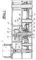
- the actuators shown in the figures are equipped with a spring return and have an electric drive 1, a reduction gear 2 of known type, a clutch 3 between the electric drive 1 and the reduction gear 2 and a brake device 4 actuated during spring return.
- the reduction gear 2 includes a return spring (not shown here) for the spring return, which can be tensioned with the actuating movement in the direction of the elevator, and an output shaft (also not shown) with the possibility of connecting an actuator.
- the clutch 3 has a drive-side clutch component 5 and a gear-side clutch component 6 that can be detached from it when the spring returns.
- the braking device 4 is designed as a centrifugal brake and comprises a stationary brake pot 7 and a rotatably mounted brake shoe carrier, on which brake shoes 8 which are radially movable by centrifugal force are arranged.
- a comparative view of FIGS. 1 and 2 also shows that the brake shoe carrier forms the transmission-side coupling component 6 and has a shaft 9 with a pinion 10 on the end that engages in the reduction gear 2.
- the drive-side coupling component 5 is rotatably mounted on the shaft shaft 9 of the brake shoe carrier 6.
- Clutch 3 and braking device 4 form a functional unit and are realized in a single mechanical assembly.
- a drive wheel 11 driven by the electric drive 1 is provided as the drive-side coupling component 5 on the shaft shaft 9 of the brake shoe carrier 6 rotatably mounted, which has a driver pin 12.
- a wrap spring 13 is arranged on the driver pin 12. This extends beyond the end of the driver pin 12 and encloses a cylindrical coupling surface 14 of a sleeve 15 fixedly arranged on the shaft shaft 9 of the brake shoe carrier 6. The wrap spring 13 establishes a non-positive connection between the driver pin 12 and the shaft shaft 9 of the brake shoe carrier 6.
- a locking device 16 is provided, which permits rotation of the wrap spring 13 in a direction of rotation exciting the restoring spring of the reduction gear, ie in the direction of the elevator, and inhibits the rotation of the wrap spring 13 in the opposite direction of rotation.
- the wrap spring 13 opens, whereby the non-positive connection between the driver pin 12 and the shaft shaft 9 of the brake shoe carrier 6 is released. This is equivalent to uncoupling the driver pin 12.
- the shaft shaft end 17 of the wrap spring is fastened to a sleeve 18 which encloses the wrap spring 13 with a gap-like spacing and is rotatably supported on the one hand on the drive wheel 11 and on the other hand on the sleeve 15 fixedly mounted on the shaft shaft 9.
- the locking device 16 consists of a locking spring 19 arranged on the jacket side of the sleeve 18 and fixed at one end. Due to the winding direction of the locking spring 19, the sleeve 18 can rotate in the direction of the elevator, however, it is blocked against return.
- the actuator shown in Fig. 1 and particularly suitable for butterfly valves works as follows.
- the wrap spring 13 couples the drive wheel 11, which is designed as a spur gear, to the shaft shaft 9 of the brake shoe carrier 6.
- the wrap spring 13 With the actuating movement of the electric drive 1, the wrap spring 13 is also rotated in the direction of the elevator. It is blocked against reverse. If the spring energy of the return spring of the actuator tensioned with the actuating movement is released, the mechanical parts rotate in the opposite direction of the elevator.
- the blocking device 16 blocks the sleeve 18, the wrap spring 13 opening its turns in the region of the cylindrical coupling surface 14 of the brake shoe carrier 6 due to the spring end suspended on the sleeve 18, which equates to a decoupling of the driver pin 12.
- the centrifugal brake 4 With the spring return, which is initiated by disengaging, the centrifugal brake 4 is activated at the same time.
- the mass of the brake shoes 8 arranged on the brake shoe carrier 6 is adjusted in such a way that they achieve a predetermined braking effect which controls the restoring movement by the friction occurring at the brake pot 7.
- the electric drive 1 preferably has an electrical control circuit with at least one capacitor which, by capacitor discharge, triggers a brief return movement of the electric drive 1 and the drive wheel 11 connected to it, which initiates the spring return, when the power supply to the actuator is interrupted.
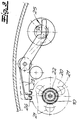
- the actuator shown in FIGS. 2 and 3 can be used for control flaps that perform adjusting movements in both directions of rotation according to predetermined control functions.
- the clutch 3 transmits torques in both directions of rotation. It is designed as a planetary gear with an outer wheel 20, planet wheels 21 and a central wheel 22.
- the central wheel 22 is rotatably supported as a drive-side coupling component on the shaft shaft 9 of the brake shoe carrier 6 and can be driven by the electric drive 1 with the interposition of pinions not shown in FIG. 2.
- the planet gears 21 are arranged on the brake shoe carrier 6.
- the outer wheel 20 is locked when the clutch is engaged, and freely rotatable when the clutch is disengaged.
- the actuator can operate in both directions of rotation as follows.
- the spring returns the locking of the outer wheel 20 is released and this can be freely rotated.
- the centrifugal brake 4 is also activated with the spring return.
- the masses of the brake shoes 6 are adjusted so that they achieve a predetermined braking effect at the number of revolutions occurring during spring return due to friction on the brake pot 7.
- a locking device with two locking levers 23 is provided in the exemplary embodiment.
- the locking levers 23 engage in an outside Ring gear 24 of the outer wheel 20 (see FIG. 3).
- the locking device also includes an electromotive eccentric drive and an electrical control circuit, not shown, with at least one capacitor, which briefly starts the eccentric drive 25 by capacitor discharge when the power supply to the actuator is interrupted.
- the latching levers 23 are released from the ring gear 24, as indicated in FIG. 3.
- the spring return is initiated with the disengagement.
Landscapes
- Engineering & Computer Science (AREA)
- Chemical & Material Sciences (AREA)
- Combustion & Propulsion (AREA)
- Mechanical Engineering (AREA)
- General Engineering & Computer Science (AREA)
- Power Engineering (AREA)
- Braking Arrangements (AREA)
- Electrically Driven Valve-Operating Means (AREA)
- Mechanically-Actuated Valves (AREA)
- One-Way And Automatic Clutches, And Combinations Of Different Clutches (AREA)
Description
- Die Erfindung betrifft einen Stellantrieb mit Federrücklauf, insbesondere für Klappen in Heizungs-, Lüftungs- und Klimaanlagen, mit einem Elektroantrieb, mit einem Untersetzungsgetriebe, welches eine die Stellbewegung spannbare Rückstellfeder für den Federrücklauf aufweist, und mit einer beim Federrücklauf betätigten Bremsvorrichtung.
- Stellantriebe mit Federrücklauf werden in der Praxis oft als Regelantriebe eingesetzt, die nach vorgegebenen Regelfunktionen sowohl in Öffnungs- als auch in Schließrichtung Stellbewegungen von zur Durchflußmengenregelung eingesetzten Stellgliedern, beispielsweise Regelklappen, ausführen. Daneben werden die Stellantriebe mit Federrücklauf auch als sogenannte AUF/ZU-Antriebe zur Betätigung von Absperrklappen eingesetzt. Das an den Stellantrieb angeschlossene Stellglied wird hierbei elektrisch entweder in die Offen- oder in die Zustellung gebracht und dort gehalten. Daneben verlangen Sicherheitsbedingungen, daß die Stellglieder im Störfall, insbesondere bei einer Unterbrechung der Stromzufuhr zu dem Elektroantrieb, eine Sicherheitsstellung einnehmen. Zu diesem Zweck ist der Federrücklauf vorgesehen. Die Federenergie der Rückstellfeder wird so auf das Stellglied übertragen, daß dieses die gewünschte Sicherheitsfunktion erfüllt, wenn die Stromzufuhr zu dem Elektroantrieb unterbrochen ist. Es sind aber auch Ausführungen bekannt, bei denen die Auslösung des Federrücklaufes durch einen Stromimpuls erfolgt. Zumeist ist die Anordnung so getroffen, daß das Stellglied unter Federkraft geschlossen wird. Die Bremse dient der Schonung des Untersetzungsgetriebes, welches bei einer plötzlichen Energiefreisetzung der Rückstellfeder Schaden nehmen würde.
- Ein Stellantrieb des eingangs beschriebenen Aufbaus ist aus WO-A-8403370 bekannt. Der Elektroantrieb und das Untersetzungsgetriebe sind auch beim Federrücklauf gekuppelt. Bei dieser Ausführung ist eine vollständige Rückstellung des Stellgliedes optimal sichergestellt.
- Der Erfindung liegt die Aufgabe zugrunde, bei einer Vorrichtung des eingangs beschriebenen Aufbaus eine Einrichtung anzugeben, die eine betriebssichere und vollständige Rückstellung des Stellgliedes ermöglicht und nur einen geringen Platzbedarf aufweist.
- Zur Lösung dieser Aufgabe lehrt die Erfindung, daß zwischen dem Elektroantrieb und dem Untersetzungsgetriebe eine Kupplung angeordnet ist, die ein antriebsseitiges Kupplungsbauteil und ein beim Federrücklauf von diesem lösbares getriebeseitiges Kupplungsbauteil aufweist, daß die Bremsvorrichtung als Fliehkraftbremse mit einem ortsfesten Bremstopf und einem drehbar gelagerten Bremsbackenträger, an dem durch Fliehkraft radial bewegliche Bremsbacken angeordnet sind, ausgebildet ist, daß der Bremsbackenträger das getriebeseitige Kupplungsbauteil bildet sowie einen Wellenschaft mit endseitigem, in das Untersetzungsgetriebe eingreifendem Ritzel aufweist und daß das antriebsseitige Kupplungsbauteil auf dem Wellenschaft des Bremsbackenträgers drehbar gelagert ist. Kupplung und Bremsvorrichtung bilden eine, in einer einzigen mechanischen Baugruppe realisierte Funktionseinheit.
- Wenn der Stellantrieb als Regelantrieb eingesetzt werden soll, also Stellbewegungen nach vorgebenen Regelfunktionen in beiden Drehrichtungen ausführbar sein müssen, ist die Kupplung so auszulegen, daß bei eingerückter Kupplung Drehmomente in beiden Drehrichtungen von dem Elektroantrieb auf das Untersetzungsgetriebe übertragbar sind. Eine bevorzugte Ausführung des erfindungsgemäßen Stellantriebes, die als Regelantrieb einsetzbar ist, ist dadurch gekennzeichnet, daß die Kupplung als Planetengetriebe mit Außenrad, Planetenrädern und Zentralrad ausgebildet ist, wobei das Zentralrad als antriebsseitiges Kupplungsbauteil auf dem Wellenschaft des Bremsbackenträgers drehbar gelagert und von dem Elektroantrieb antreibbar ist, wobei die Planetenräder an dem Bremsbackenträger angeordnet sind und wobei das Außenrad bei eingerückter Kupplung arretiert und bei ausgerückter Kupplung frei drehbar ist. Eingerückte Kupplung bezeichnet den Betriebszustand, bei dem ein Kraftfluß von dem Elektroantrieb auf das Untersetzungsgetriebe gewährleistet ist. Ausgerückte Kupplung meint den Betriebszustand, bei dem der Kraftfluß von dem Elektroantrieb auf das Untersetzungsgetriebe unterbrochen ist. Solange das Außenrad arretiert ist, kann der Stellantrieb wie folgt in beiden Drehrichtungen operieren. Das vom Elektroantrieb angetriebene Zentralrad treibt über die Planetenräder den Bremsbackenträger und das mit diesem fest verbundene Ritzel an. Über das Untersetzungsgetriebe überträgt sich die Ritzelbewegung auf das Stellglied, wobei nach Maßgabe des Stellwegs auch die Rückstellfeder für den Federrücklauf gespannt wird. Die Rotationsgeschwindigkeit des Bremsbackenträgers ist durch das Untersetzungsverhältnis des Planetengetriebes so klein, daß die Fliehkraftbremse bei dieser Stellbewegung nicht anspricht. Bei ausgerückter Kupplung ist das Außenrad frei drehbar. Durch die Drehbeweglichkeit des Außenrades ist der Kraftfluß zwischen Antriebsrad und Untersetzungsgetriebe unterbrochen, was einer Auskupplung gleichkommt. Mit der Auskupplung wird der Federrücklauf eingeleitet. Die Federenergie der Rückstellfeder wird freigesetzt, wobei über das Untersetzungsgetriebe der Bremsbackenträger angetrieben wird. Dabei wird die Fliehkraftbremse aktiv. Die Masse der an dem Bremsbackenträger angeordneten Bremsbacken ist so abgestimmt, daß die Bremsbacken bei den entstehenden Umdrehungszahlen durch Reibung am Bremstopf eine vorgegebene Bremswirkung erzielen.
- Für die Arretierung des Außenrades bestehen verschiedene konstruktive Möglichkeiten. Eine konstruktiv bevorzugte Lösung ist dadurch gekennzeichnet, daß das drehbar gelagerte Außenrad einen außenseitigen Zahnkranz aufweist und daß in den Zahnkranz mindestens ein Rasthebel einer Sperreinrichtung eingreift, der zur Einleitung des Federrücklaufs den Rasthebel von dem Zahnkranz löst. In weiterer Ausgestaltung lehrt die Erfindung, daß die Sperreinrichtung einen elektromotorischen Exzenterantrieb und eine elektrische Steuerschaltung mit mindestens einem Kondensator aufweist, die durch Kondensatorentladung den Exzenterantrieb kurzzeitig in Betrieb setzt, wenn die Stromzufuhr zum Stellantrieb unterbrochen ist. Das Ausrasten des oder der Rasthebel wird durch einen Kurzbetrieb des elektromotorischen Exzenterantriebs bewerkstelligt. Bei einer Stromunterbrechung ist dadurch eine sofortige Auskupplung gewährleistet, welche den Federrücklauf einleitet.
- Stellantriebe mit Federrücklauf werden, wie eingangs bereits erläutert, auch als AUF/ZU-Antriebe zur Betätigung von Absperrklappen verwendet. Eine Ausführung des Stellantriebes, die für diese Anwendung besonders geeignet ist, ist erfindungsgemäß dadurch gekennzeichnet, daß als antriebsseitiges Kupplungsbauteil auf dem Wellenschaft des Bremsbackenträgers ein von dem Elektroantrieb angetriebenes Antriebsrad drehbar gelagert ist, welches einen Treiberzapfen aufweist, daß auf dem Treiberzapfen eine Schlingfeder angeordnet ist, deren anderes Ende eine auf dem Wellenschaft des Bremsbackenträgers angeordnete zylindrische Kupplungsfläche unter Bildung einer kraftschlüssigen Verbindung zwischen dem Treiberzapfen und dem Wellenschaft des Bremsbackenträgers fest umschließt, und daß eine Sperrvorrichtung vorgesehen ist, welche eine Rotation der Schlingfeder in einer die Rückstellfeder des Untersetzungsgetriebes spannenden Drehrichtung zuläßt sowie die Rotation der Schlingfeder in entgegengesetzter Drehrichtung hemmt. Die Schlingfeder öffnet beim Federrücklauf des Untersetzungsgetriebes, wodurch die kraftschlüssige Verbindung zwischen dem Treiberzapfen und dem Wellenschaft des Bremsbackenträgers lösbar ist. Bei dieser Ausführungsform überträgt die Kupplung Drehmomente nur in einer Drehrichtung. Bei entgegengesetzter Drehrichtung erfolgt stets eine Auskupplung. Beim Federrücklauf wird auch hier die Fliehkraftbremse in der bereits beschriebenen Weise aktiviert.
- In weiterer konstruktiver Ausgestaltung lehrt die Erfindung, daß das wellenschaftseitige Ende der Schlingfeder an einer Hülse befestigt ist, welche die Schlingfeder mit Spaltabstand mantelförmig umschließt und an dem Antriebsrad sowie an dem Wellenschaft drehbeweglich abgestützt ist. Die Sperrvorrichtung arbeitet auf die Hülse. Im Rahmen der Erfindung liegt es, den Wellenschaft einstückig mit einer Lagerfläche für die Hülse sowie mit der zylindrischen Kupplungsfläche auszubilden. Vorzugsweise ist auf dem Wellenschaft des Bremsbackenträgers jedoch eine Muffe befestigt, die einen Bund für die Lagerung der Hülse sowie die Kupplungsfläche aufweist. Die Sperreinrichtung kann dadurch verwirklicht werden, daß an der Mantelaußenseite der Hülse eine an einem Ende fixierte Sperrfeder angeordnet ist, die eine Rotation der Hülse nur in einer Drehrichtung zuläßt. Der Auskupplungsvorgang kann schließlich durch eine kurze Rückdrehung des Treiberzapfens weiter optimiert werden. Vorzugsweise weist der Elektroantrieb daher eine elektrische Steuerschaltung mit mindestens einem Kondensator auf, die durch Kondensatorentladung eine kurzzeitige, den Federrücklauf einleitende Rückdrehbewegung des Elektroantriebes und des an diesen angeschlossenen Antriebsrades auslöst, wenn die Stromzufuhr zu dem Stellantrieb unterbrochen ist.
- Im folgenden wird die Erfindung anhand einer lediglich ein Ausführungsbeispiel darstellenden Zeichnung ausführlich erläutert. Es zeigen jeweils ausschnittsweise und schematisch
- Fig. 1
- den Längsschnitt durch einen Stellantrieb mit Federrücklauf in einer für Absperrklappen geeigneten Ausführungsform,
- Fig. 2
- den Längsschnitt durch einen Stellantrieb mit Federrücklauf in einer insbesondere für Regelklappen geeigneten Ausführungsform,
- Fig. 3
- die Ansicht A-A in Fig. 2.
- Die in den Figuren dargestellten Stellantriebe sind mit einem Federrücklauf ausgerüstet und weisen einen Elektroantrieb 1, ein Untersetzungsgetriebe 2 bekannter Bauart, eine Kupplung 3 zwischen dem Elektroantrieb 1 und dem Untersetzungsgetriebe 2 sowie eine beim Federrücklauf betätigte Bremsvorrichtung 4 auf. Zum Untersetzungsgetriebe 2 gehört eine hier nicht dargestellte Rückstellfeder für den Federrücklauf, die mit der Stellbewegung in Aufzugsrichtung spannbar ist, sowie eine ebenfalls nicht dargestellte Abtriebswelle mit Anschlußmöglichkeit für ein Stellglied.
- Die Kupplung 3 weist ein antriebsseitiges Kupplungsbauteil 5 und ein beim Federrücklauf von diesem lösbares getriebeseitiges Kupplungsbauteil 6 auf. Die Bremsvorrichtung 4 ist als Fliehkraftbremse ausgeführt und umfaßt einen ortsfesten Bremstopf 7 sowie einen drehbar gelagerten Bremsbackenträger, an dem durch Fliehkraft radial bewegliche Bremsbacken 8 angeordnet sind. Einer vergleichenden Betrachtung der Fig. 1 und 2 entnimmt man ferner, daß der Bremsbackenträger das getriebeseitige Kupplungsbauteil 6 bildet und einen Wellenschaft 9 mit endseitigem, in das Untersetzungsgetriebe 2 eingreifendem Ritzel 10 aufweist. Das antriebsseitige Kupplungsbauteil 5 ist auf dem Wellenschaft 9 des Bremsbackenträgers 6 drehbar gelagert. Kupplung 3 und Bremsvorrichtung 4 bilden eine Funktionseinheit und sind in einer einzigen mechanischen Baugruppe realisiert.
- Bei der in Fig. 1 dargstellten Ausführung ist als antriebsseitiges Kupplungsbauteil 5 auf dem Wellenschaft 9 des Bremsbackenträgers 6 ein von dem Elektroantrieb 1 angetriebenes Antriebsrad 11 drehbar gelagert, welches einen Treiberzapfen 12 aufweist. Auf dem Treiberzapfen 12 ist eine Schlingfeder 13 angeordnet. Diese erstreckt sich über das Ende des Treiberzapfens 12 hinaus und umschließt eine zylindrische Kupplungsfläche 14 einer auf dem Wellenschaft 9 des Bremsbackenträgers 6 fest angeordneten Muffe 15. Die Schlingfeder 13 stellt eine kraftschlüssige Verbindung zwischem dem Treiberzapfen 12 und dem Wellenschaft 9 des Bremsbackenträgers 6 her. Ferner ist eine Sperrvorrichtung 16 vorgesehen, welche eine Rotation der Schlingfeder 13 in einer die Rückstellfeder des Untersetzungsgetriebes spannenden Drehrichtung, also in der Aufzugsrichtung, zuläßt sowie die Rotation der Schlingfeder 13 in entgegengesetzter Drehrichtung hemmt. Beim Federrücklauf öffnet die Schlingfeder 13, wodurch die kraftschlüssige Verbindung zwischen dem Treiberzapfen 12 und dem Wellenschaft 9 des Bremsbackenträgers 6 gelöst ist. Dies kommt einer Abkupplung des Treiberzapfens 12 gleich.
- Das wellenschaftseitige Ende 17 der Schlingfeder ist an einer Hülse 18 befestigt, welche die Schlingfeder 13 mit Spaltabstand mantelförmig umschließt und einerseits an dem Antriebsrad 11 sowie andererseits an der auf dem Wellenschaft 9 fest montierten Muffe 15 drehbeweglich abgestützt ist. Die Sperrvorrichtung 16 besteht im Ausführungsbeispiel aus einer an der Mantelseite der Hülse 18 angeordneten Sperrfeder 19, die an einem Ende fixiert ist. Bedingt durch den Wicklungssinn der Sperrfeder 19 kann die Hülse 18 in Aufzugsrichtung mitdrehen, hingegen wird sie gegen Rücklauf blockiert.
- Der in Fig. 1 dargestellte und insbesondere für Absperrklappen geeignete Stellantrieb arbeitet wie folgt. Bei einer Betätigung des Elektroantriebes 1 kuppelt die Schlingfeder 13 das als Stirnrad ausgeführte Antriebsrad 11 mit dem Wellenschaft 9 des Bremsbackenträgers 6. Mit der Stellbewegung des Elektroantriebes 1 wird die Schlingfeder 13 in Aufzugsrichtung mitgedreht. Gegen Rücklauf ist sie blockiert. Wird die Federenergie der mit der Stellbewegung gespannten Rückstellfeder des Stellantriebes freigesetzt, so drehen die mechanischen Teile entgegen der Aufzugsrichtung. Die Sperrvorrichtung 16 blockiert die Hülse 18, wobei die Schlingfeder 13 durch das an der Hülse 18 eingehängte Federende im Bereich der zylindrischen Kupplungsfläche 14 des Bremsbackenträgers 6 ihre Windungen öffnet, was einem Abkuppeln des Treiberzapfens 12 gleichkomt. Mit dem Federrücklauf, der durch das Auskuppeln eingeleitet wird, wird gleichzeitig die Fliehkraftbremse 4 aktiviert. Die Masse der auf dem Bremsbackenträger 6 angeordneten Bremsbacken 8 ist so abgestimmt, daß sie bei den auftretenden Umdrehungszahlen durch Reibung am Bremstopf 7 eine vorgegebene, die Rückstellbewegung kontrollierende Bremswirkung erzielen.
- Der Auskupplungsvorgang kann durch ein kurzes Rückdrehen des Treiberzapfens 12 weiter optimiert werden. Zu diesem Zweck weist der Elektroantrieb 1 vorzugsweise eine elektrische Steuerschaltung mit mindestens einem Kondensator auf, die durch Kondensatorentladung eine kurzzeitige, den Federrücklauf einleitende Rückdrehbewegung des Elektroantriebes 1 und des an diesen angeschlossenen Antriebsrades 11 auslöst, wenn die Stromzufuhr zu dem Stellantrieb unterbrochen ist.
- Der in den Fig. 2 und 3 dargestellte Stellantrieb ist für Regelklappen einsetzbar, die nach vorgegebenen Stellfunktionen Stellbewegungen in beiden Drehrichtungen ausführen. Die Kupplung 3 überträgt im Unterschied zu der zuvor beschriebenen Ausführung Drehmomente in beiden Drehrichtungen. Sie ist als Planetengetriebe mit Außenrad 20, Planetenrädern 21 und Zentralrad 22 ausgebildet. Das Zentralrad 22 ist als antriebsseitiges Kupplungsbauteil auf dem Wellenschaft 9 des Bremsbackenträgers 6 drehbar gelagert und von dem Elektroantrieb 1 unter Zwischenschaltung von in Fig. 2 nicht näher dargestellten Ritzeln antreibbar. Die Planetenräder 21 sind an dem Bremsbackenträger 6 angeordnet. Bei eingerückter Kupplung ist das Außenrad 20 arretiert, bei ausgerückter Kupplung frei drehbar. So lange das Außenrad 20 arretiert ist, kann der Stellantrieb in beiden Drehrichtungen wie folgt operieren. Das von dem Elektroantrieb 1 angetriebene Zentralrad 22 treibt über die Planetenräder 21 den Bremsbackenträger 6 und das mit diesem fest verbundene Ritzel 10 an, welches in das in Fig. 2 nicht näher dargestellte Untersetzungsgetriebe eingreift. Beim Federrücklauf ist die Arretierung des Außenrades 20 gelöst und dieses frei drehbar. Dadurch ist der Kraftfluß zwischen dem Ritzel 10 und dem Zentralrad 22 unterbrochen, was einer Auskupplung gleichkommt. Mit dem Federrücklauf wird ferner die Fliehkraftbremse 4 aktiviert. Die Massen der Bremsbacken 6 sind so abgestimmt, daß sie bei den beim Federrücklauf auftretenden Umdrehungszahlen durch Reibung am Bremstopf 7 eine vorgegebene Bremswirkung erzielen.
- Zur Arretierung des drehbar gelagerten Außenrades ist eine Sperreinrichtung mit im Ausführungsbeispiel zwei Rasthebeln 23 vorgesehen. Die Rasthebel 23 greifen in einen außenseitigen Zahnkranz 24 des Außenrades 20 ein (vgl. Fig. 3). Zur Sperreinrichtung gehören ferner ein elektromotorischer Exzenterantrieb und eine elektrische nicht dargestellte Steuerschaltung mit mindestens einem Kondensator, die durch Kondensatorentladung den Exzenterantrieb 25 kurzzeitig in Betrieb setzt, wenn die Stromzufuhr zu dem Stellantrieb unterbrochen ist. Durch Kurzbetrieb des Exzenterantriebes 25 werden die Rasthebel 23, wie in Fig. 3 angedeutet, von dem Zahnkranz 24 gelöst. Mit der Auskupplung wird der Federrücklauf eingeleitet.
Claims (9)
- Stellantrieb mit Federrücklauf, insbesondere für Klappen in Heizungs-, Lüftungs- und Klimaanlagen, - miteinem Elektroantrieb (1),einem Untersetzungsgetriebe (2), welches eine mit der Stellbewegung spannbare Rückstellfeder für den Federrücklauf aufweist, undeiner beim Federrücklauf betätigten Bremsvorrichtung (4),dadurch gekennzeichnet, daß zwischen dem Elektroantrieb (1) und dem Untersetzungsgetriebe (2) eine Kupplung (3) angeordnet ist, die ein antriebsseitiges Kupplungsbauteil (5) und ein beim Federrücklauf von diesem lösbares getriebeseitiges Kupplungsbauteil (6) aufweist, daß die Bremsvorrichtung (4) als Fliehkraftbremse mit einem ortsfesten Bremstopf (7) und einem drehbar gelagerten Bremsbackenträger, an dem durch Fiehkraft radial bewegliche Bremsbacken (8) angeordnet sind, ausgebildet ist, daß der Bremsbackenträger das getriebeseitige Kupplungsbauteil (6) bildet, sowie einen Wellenschaft (9) mit endseitigem, in das Untersetzungsgetriebe (2) eingreifendem Ritzel (10) aufweist und daß das antriebsseitige Kupplungsbauteil (5) auf dem Wellenschaft des Bremsbackenträgers (6) drehbar gelagert ist.
- Stellantrieb nach Anspruch 1, dadurch gekennzeichnet, daß die Kupplung (3) als Planetengetriebe mit Außenrad (20), Planetenrädern (21) und Zentralrad (22) ausgebildet ist, wobei das Zentralrad (22) als antriebsseitiges Kupplungsbauteil (5) auf dem Wellenschaft (9) des Bremsbackenträgers (6) drehbar gelagert und von dem Elektroantrieb (1) antreibbar ist, wobei die Planetenräder (21) an dem Bremsbackenträger (6) angeordnet sind und wobei das Außenrad (2) bei eingerückter Kupplung arretiert und bei ausgerückter Kupplung frei drehbar ist.
- Stellantrieb nach Anspruch 2, dadurch gekennzeichnet, daß das drehbar gelagerte Außenrad (20) einen außenseitigen Zahnkranz (24) aufweist und daß in den Zahnkranz (24) mindestens ein Rasthebel (23) einer Sperreinrichtung eingreift, die zur Einleitung des Federrücklaufes den Rasthebel (23) von dem Zahnkranz (24) löst.
- Stellantrieb nach Anspruch 3, dadurch gekennzeichnet, daß die Sperreinrichtung einen elektromotorischen Exzenterantrieb (25) und eine elektrische Steuerschaltung mit mindestens einem Kondensator aufweist, die durch Kondensatorentladung den Exzenterantrieb (25) kurzzeitig in Betrieb setzt, wenn die Stromzufuhr zu dem Stellantrieb unterbrochen ist.
- Stellantrieb nach Anspruch 1, dadurch gekennzeichnet, daß als antriebsseitiges Kupplungsbauteil (5) auf dem Wellenschaft (9) des Bremsbackenträgers (6) ein von dem Elektroantrieb (1) angetriebenes Antriebsrad (11) drehbar gelagert ist, welches einen Treiberzapfen (12) aufweist, daß auf dem Treibenzapfen (12) eine Schlingfeder (13) angeordnet ist, deren anderes Ende eine auf dem Wellenschaft (9) des Bremsbackenträgers (6) angeordnete zylindrische Kupplungsfläche (14) unter Bildung einer kraftschlüssigen Verbindung zwischen dem Treiberzapfen (12) und dem Wellenschaft (9) des Bremsbackenträgers (6) fest umschließt, und daß eine Sperrvorrichtung (16) vorgesehen ist, welche eine Rotation der Schlingfeder (13) in einer die Rückstellfeder des Untersetzungsgetriebes spannenden Drehrichtung zuläßt sowie die Rotation der Schlingfeder (13) in entgegengesetzter Drehrichtung hemmt, wobei die Schlingfeder (13) beim Federrücklauf des Untersetzungsgetriebes öffnet und dadurch die kraftschlüssige Verbindung zwischen dem Treiberzapfen (12) und dem Wellenschaft (9) des Bremsbackenträgers (6) lösbar ist.
- Stellantrieb nach Anspruch 5, dadurch gekennzeichnet, daß das wellenschaftseitige Ende (17) der Schlingfeder (13) an einer Hülse (18) befestigt ist, welche die Schlingfeder (13) mit Spaltabstand mantelförmig umschließt und an dem Antriebsrad (11) sowie an dem Wellenschaft (9) drehbeweglich abgestützt ist, und daß die Sperrvorrichtung (16) auf die Hülse (18) arbeitet.
- Stellantrieb nach Anspruch 6, dadurch gekennzeichnet, daß auf dem Wellenschaft (9) des Bremsbackenträgers (6) eine Muffe (15) befestigt ist, die den Bund für die Lagerung der Hülse (18) sowie die Kupplungsfläche (14) aufweist.
- Stellantrieb nach Anspruch 6 oder 7, dadurch gekennzeichnet, daß an der Mantelaußenseite der Hülse (18) eine an einem Ende fixierte Sperrfeder (19) angeordnet ist, die eine Rotation der Hülse (18) nur in einer Drehrichtung zuläßt.
- Stellantrieb nach einem der Ansprüche 5 bis 8, dadurch gekennzeichnet, daß der Elektroantrieb (1) eine elektrische Steuerschaltung mit mindestens einem Kondensator aufweist, die durch Kondensatorentladung eine kurzzeitige, den Federrücklauf einleitende Rückdrehbewegung des Elektroantriebes (1) und des an diesen angeschlossenen Antriebsrades (11) auslöst, wenn die Stromzufuhr zu dem Stellantrieb unterbrochen ist.
Priority Applications (7)
| Application Number | Priority Date | Filing Date | Title |
|---|---|---|---|
| ES94112825T ES2111221T3 (es) | 1994-08-17 | 1994-08-17 | Servoaccionamiento con mecanismo de retroceso elastico. |
| DE59404834T DE59404834D1 (de) | 1994-08-17 | 1994-08-17 | Stellantrieb mit Federrücklauf |
| EP94112825A EP0697571B1 (de) | 1994-08-17 | 1994-08-17 | Stellantrieb mit Federrücklauf |
| US08/509,772 US5662542A (en) | 1994-08-17 | 1995-08-01 | Actuating drive having a spring return feature |
| CA002155466A CA2155466C (en) | 1994-08-17 | 1995-08-04 | An actuating drive having a spring return feature |
| AU28536/95A AU676641B2 (en) | 1994-08-17 | 1995-08-14 | An actuating drive having a spring return feature |
| JP7209748A JPH08178119A (ja) | 1994-08-17 | 1995-08-17 | ばね復帰アクチュエータ |
Applications Claiming Priority (1)
| Application Number | Priority Date | Filing Date | Title |
|---|---|---|---|
| EP94112825A EP0697571B1 (de) | 1994-08-17 | 1994-08-17 | Stellantrieb mit Federrücklauf |
Publications (2)
| Publication Number | Publication Date |
|---|---|
| EP0697571A1 EP0697571A1 (de) | 1996-02-21 |
| EP0697571B1 true EP0697571B1 (de) | 1997-12-17 |
Family
ID=8216213
Family Applications (1)
| Application Number | Title | Priority Date | Filing Date |
|---|---|---|---|
| EP94112825A Expired - Lifetime EP0697571B1 (de) | 1994-08-17 | 1994-08-17 | Stellantrieb mit Federrücklauf |
Country Status (7)
| Country | Link |
|---|---|
| US (1) | US5662542A (de) |
| EP (1) | EP0697571B1 (de) |
| JP (1) | JPH08178119A (de) |
| AU (1) | AU676641B2 (de) |
| CA (1) | CA2155466C (de) |
| DE (1) | DE59404834D1 (de) |
| ES (1) | ES2111221T3 (de) |
Cited By (2)
| Publication number | Priority date | Publication date | Assignee | Title |
|---|---|---|---|---|
| US9182140B2 (en) | 2004-10-06 | 2015-11-10 | Google Inc. | Battery-operated wireless zone controllers having multiple states of power-related operation |
| US9208676B2 (en) | 2013-03-14 | 2015-12-08 | Google Inc. | Devices, methods, and associated information processing for security in a smart-sensored home |
Families Citing this family (21)
| Publication number | Priority date | Publication date | Assignee | Title |
|---|---|---|---|---|
| JP3277485B2 (ja) * | 1996-12-02 | 2002-04-22 | 株式会社山武 | 電動アクチュエータ |
| US6100655A (en) * | 1999-02-19 | 2000-08-08 | Mcintosh; Douglas S. | Mechanical return fail-safe actuator for damper, valve, elevator or other positioning device |
| US6084365A (en) * | 1999-04-29 | 2000-07-04 | Siemens Building Technologies, Inc. | Actuator having timer-controlled power switching device |
| EP1258969B1 (de) * | 2001-05-18 | 2007-10-03 | Siemens Schweiz AG | Stellantrieb mit einer Fliehkraftbremse |
| DE60321840D1 (de) * | 2002-01-03 | 2008-08-14 | Parker Hannifin Corp | Geräuschdämpfende Einrichtung für eine Zapfwellengetriebevorrichtung |
| DE20204755U1 (de) * | 2002-03-25 | 2003-05-28 | Meltem Wärmerückgewinnung GmbH & Co. KG, 82239 Alling | Luftaustauschvorrichtung |
| US20050205819A1 (en) * | 2004-03-17 | 2005-09-22 | William Morrison | Valve for reducing water hammer |
| USD598982S1 (en) | 2005-01-14 | 2009-08-25 | Honeywell International Inc. | Zone valve actuator cover |
| US20100039003A1 (en) * | 2006-09-06 | 2010-02-18 | Elodrive Gmbh | Electromotive actuating drive |
| US8020777B2 (en) | 2007-01-29 | 2011-09-20 | Lawrence Kates | System and method for budgeted zone heating and cooling |
| WO2008122140A1 (de) * | 2007-04-04 | 2008-10-16 | Newenta Ag | Stellantrieb für eine brandschutzklappe |
| US7752933B2 (en) * | 2007-05-18 | 2010-07-13 | Tac, Llc | Speed controlled spring return actuator |
| US8074894B2 (en) * | 2008-11-18 | 2011-12-13 | Honeywell International Inc. | Secondary mixing valve hot port |
| US8733666B2 (en) * | 2008-11-18 | 2014-05-27 | Honeywell International Inc. | Thermostatic mixing valve with tamper resistant adjustment feature |
| KR101278243B1 (ko) * | 2012-01-26 | 2013-06-24 | 이창국 | 위치 복귀식 모터 |
| DE102016113117A1 (de) * | 2016-07-15 | 2018-01-18 | Samson Aktiengesellschaft | Elektrischer Stellantrieb und Stellgerät mit einem elektrischen Stellantrieb |
| JP6758211B2 (ja) | 2017-02-03 | 2020-09-23 | アズビル株式会社 | 操作器 |
| JP6758212B2 (ja) | 2017-02-03 | 2020-09-23 | アズビル株式会社 | 操作器 |
| JP6842939B2 (ja) | 2017-02-03 | 2021-03-17 | アズビル株式会社 | 操作器 |
| DE102022124302A1 (de) * | 2022-09-21 | 2024-03-21 | Trox Gmbh | Verfahren zur Steuerung einer in einem Luftkanal einer raumlufttechnischen Anlage, vorzugsweise in einem als Abluftkanal oder als Fortluftkanal einer gewerblichen Küche ausgebildeten Luftkanal einer raumlufttechnischen Anlage, installierten Brandschutzklappe sowie Brandschutzklappe |
| KR20240135908A (ko) | 2023-03-06 | 2024-09-13 | 현대자동차주식회사 | 차고 제어시스템 |
Family Cites Families (16)
| Publication number | Priority date | Publication date | Assignee | Title |
|---|---|---|---|---|
| US2659249A (en) * | 1950-04-06 | 1953-11-17 | Lear Inc | Two-speed planetary transmission |
| US2984126A (en) * | 1958-05-28 | 1961-05-16 | Bowmar Instrument Corp | Gear mechanism |
| US3465605A (en) * | 1967-11-15 | 1969-09-09 | Burroughs Corp | Pawl and ratchet mechanism |
| IT1033333B (it) * | 1974-04-24 | 1979-07-10 | Nixdorf Computer Ag | Giunto con molla elicoidale cilindrica |
| US3921264A (en) * | 1974-07-08 | 1975-11-25 | Itt | Electrically operated rotational actuator with failsafe disengagement |
| US4585115A (en) * | 1982-02-16 | 1986-04-29 | Sperry Corporation | Electric clutch brake apparatus |
| JPS58165188U (ja) * | 1982-04-30 | 1983-11-02 | ト−ソ−株式会社 | ロ−ルブラインドの減速装置 |
| US4554496A (en) * | 1983-02-25 | 1985-11-19 | Johnson Service Company | Controllable rotary actuator |
| GB8419238D0 (en) * | 1984-07-27 | 1984-08-30 | Ae Plc | Actuators |
| US4760903A (en) * | 1987-05-18 | 1988-08-02 | Ncr Corporation | Method and apparatus for extending the life of a wrap spring clutch |
| EP0330804A1 (de) * | 1988-03-01 | 1989-09-06 | MOTTURA S.p.A. | Rollvorhang mit einer Bremsvorrichtung mit zentrifugal wirkenden Massen ausserhalb der Trommel angeordnet, und ein mit dieser Bremsvorrichtung ausgestattetes Lager |
| US4951021A (en) * | 1988-10-28 | 1990-08-21 | Eaton Corporation | Electromagnetic switching apparatus having dynamically balanced latch trip |
| JP2535802Y2 (ja) * | 1991-10-22 | 1997-05-14 | 株式会社 神崎高級工機製作所 | 駐車ロック装置 |
| US5454765A (en) * | 1993-05-10 | 1995-10-03 | Sommer Company | Electrically energized oil shear drive system |
| US5365804A (en) * | 1993-06-02 | 1994-11-22 | Saturn Corporation | Parking mechanism for a power transmission |
| US5518462A (en) * | 1994-08-12 | 1996-05-21 | Jordan Controls, Inc. | Spring return electric actuator |
-
1994
- 1994-08-17 EP EP94112825A patent/EP0697571B1/de not_active Expired - Lifetime
- 1994-08-17 ES ES94112825T patent/ES2111221T3/es not_active Expired - Lifetime
- 1994-08-17 DE DE59404834T patent/DE59404834D1/de not_active Expired - Fee Related
-
1995
- 1995-08-01 US US08/509,772 patent/US5662542A/en not_active Expired - Lifetime
- 1995-08-04 CA CA002155466A patent/CA2155466C/en not_active Expired - Fee Related
- 1995-08-14 AU AU28536/95A patent/AU676641B2/en not_active Ceased
- 1995-08-17 JP JP7209748A patent/JPH08178119A/ja active Pending
Cited By (10)
| Publication number | Priority date | Publication date | Assignee | Title |
|---|---|---|---|---|
| US9182140B2 (en) | 2004-10-06 | 2015-11-10 | Google Inc. | Battery-operated wireless zone controllers having multiple states of power-related operation |
| US9194599B2 (en) | 2004-10-06 | 2015-11-24 | Google Inc. | Control of multiple environmental zones based on predicted changes to environmental conditions of the zones |
| US9194600B2 (en) | 2004-10-06 | 2015-11-24 | Google Inc. | Battery charging by mechanical impeller at forced air vent outputs |
| US9222692B2 (en) | 2004-10-06 | 2015-12-29 | Google Inc. | Wireless zone control via mechanically adjustable airflow elements |
| US9273879B2 (en) | 2004-10-06 | 2016-03-01 | Google Inc. | Occupancy-based wireless control of multiple environmental zones via a central controller |
| US9303889B2 (en) | 2004-10-06 | 2016-04-05 | Google Inc. | Multiple environmental zone control via a central controller |
| US9316407B2 (en) | 2004-10-06 | 2016-04-19 | Google Inc. | Multiple environmental zone control with integrated battery status communications |
| US9353964B2 (en) | 2004-10-06 | 2016-05-31 | Google Inc. | Systems and methods for wirelessly-enabled HVAC control |
| US9353963B2 (en) | 2004-10-06 | 2016-05-31 | Google Inc. | Occupancy-based wireless control of multiple environmental zones with zone controller identification |
| US9208676B2 (en) | 2013-03-14 | 2015-12-08 | Google Inc. | Devices, methods, and associated information processing for security in a smart-sensored home |
Also Published As
| Publication number | Publication date |
|---|---|
| JPH08178119A (ja) | 1996-07-12 |
| AU676641B2 (en) | 1997-03-13 |
| US5662542A (en) | 1997-09-02 |
| AU2853695A (en) | 1996-03-07 |
| DE59404834D1 (de) | 1998-01-29 |
| CA2155466C (en) | 1999-03-16 |
| ES2111221T3 (es) | 1998-03-01 |
| EP0697571A1 (de) | 1996-02-21 |
| CA2155466A1 (en) | 1996-02-18 |
Similar Documents
| Publication | Publication Date | Title |
|---|---|---|
| EP0697571B1 (de) | Stellantrieb mit Federrücklauf | |
| DE112007002049B4 (de) | Feder-Rückstellventil mit Betätigungseinrichtung | |
| DE3909150C2 (de) | ||
| DE10207540B4 (de) | Motorvorrichtung zum Betätigen einer Fahrzeugtürbetätigungsvorrichtung | |
| EP0064763B1 (de) | Antrieb, insbesondere Verstellantrieb für Kraftfahrzeuge | |
| EP0666399B1 (de) | Antriebsvorrichtung für ein zwischen Endstellungen verstellbares Teil eines Fahrzeuges | |
| WO2018001476A1 (de) | Parksperreneinheit und elektroantriebsanordnung mit einer parksperre | |
| DE102016214682A1 (de) | Sperranordnung | |
| DE2437778A1 (de) | Motorisch betaetigtes ventil mit einer drehmomentsbegrenzenden bremse | |
| EP0250852B1 (de) | Doppeltwirkender Drehantrieb für ein Stellorgan | |
| DE102021203008A1 (de) | Betätigungseinrichtung für eine elektromechanisch betätigbare Kraftfahrzeugbremse | |
| EP0460372B1 (de) | Einrichtung zum selbsttätigen Nachstellen einer Bremse, insbesondere Fahrzeugbremse | |
| DE19734815C1 (de) | Antriebsvorrichtung für ein verstellbares Fahrzeugteil | |
| EP0447504B1 (de) | Elektromotorische servolenkung | |
| DE2064788C3 (de) | Antriebs- beziehungsweise Betäti- gungsanordnung für eine Bremsvorrichtung | |
| EP0716242B1 (de) | Elektromotorische Betätigung einer Reibscheibenkupplung | |
| DE60211292T2 (de) | Differenzdrehmomentbegrenzer | |
| DE3420789A1 (de) | Antriebseinheit | |
| DE3239046A1 (de) | Stellantrieb fuer die betaetigung von absperrorganen in kraftfahrzeug-heizungs- und/oder -klimaanlagen | |
| DE19532590B4 (de) | Motor- und handbetätigbarer Stellantrieb | |
| EP1412628B1 (de) | Antriebseinrichtung | |
| DE19604501C2 (de) | Getriebe | |
| EP1019606A1 (de) | Torwellenantriebsaggregat für tore mit einer antriebs- und/oder torsionsfeder-welle | |
| EP1028223B1 (de) | Hilfsantriebsvorrichtung zum hilfsweisen Antreiben eines Gebäudeverschlusses | |
| EP1279789A1 (de) | Trennvorrichtung für eine Antriebseinrichtung |
Legal Events
| Date | Code | Title | Description |
|---|---|---|---|
| PUAI | Public reference made under article 153(3) epc to a published international application that has entered the european phase |
Free format text: ORIGINAL CODE: 0009012 |
|
| 17P | Request for examination filed |
Effective date: 19950128 |
|
| AK | Designated contracting states |
Kind code of ref document: A1 Designated state(s): BE CH DE ES FR GB IT LI NL |
|
| 17Q | First examination report despatched |
Effective date: 19960725 |
|
| GRAG | Despatch of communication of intention to grant |
Free format text: ORIGINAL CODE: EPIDOS AGRA |
|
| GRAG | Despatch of communication of intention to grant |
Free format text: ORIGINAL CODE: EPIDOS AGRA |
|
| GRAH | Despatch of communication of intention to grant a patent |
Free format text: ORIGINAL CODE: EPIDOS IGRA |
|
| GRAH | Despatch of communication of intention to grant a patent |
Free format text: ORIGINAL CODE: EPIDOS IGRA |
|
| GRAA | (expected) grant |
Free format text: ORIGINAL CODE: 0009210 |
|
| AK | Designated contracting states |
Kind code of ref document: B1 Designated state(s): BE CH DE ES FR GB IT LI NL |
|
| REG | Reference to a national code |
Ref country code: CH Ref legal event code: EP |
|
| REG | Reference to a national code |
Ref country code: CH Ref legal event code: NV Representative=s name: KELLER & PARTNER PATENTANWAELTE AG |
|
| ITF | It: translation for a ep patent filed | ||
| REF | Corresponds to: |
Ref document number: 59404834 Country of ref document: DE Date of ref document: 19980129 |
|
| ET | Fr: translation filed | ||
| GBT | Gb: translation of ep patent filed (gb section 77(6)(a)/1977) |
Effective date: 19980126 |
|
| REG | Reference to a national code |
Ref country code: ES Ref legal event code: FG2A Ref document number: 2111221 Country of ref document: ES Kind code of ref document: T3 |
|
| PLBE | No opposition filed within time limit |
Free format text: ORIGINAL CODE: 0009261 |
|
| STAA | Information on the status of an ep patent application or granted ep patent |
Free format text: STATUS: NO OPPOSITION FILED WITHIN TIME LIMIT |
|
| 26N | No opposition filed | ||
| PGFP | Annual fee paid to national office [announced via postgrant information from national office to epo] |
Ref country code: NL Payment date: 20010807 Year of fee payment: 8 |
|
| PGFP | Annual fee paid to national office [announced via postgrant information from national office to epo] |
Ref country code: BE Payment date: 20010903 Year of fee payment: 8 |
|
| PGFP | Annual fee paid to national office [announced via postgrant information from national office to epo] |
Ref country code: ES Payment date: 20010906 Year of fee payment: 8 |
|
| REG | Reference to a national code |
Ref country code: GB Ref legal event code: IF02 |
|
| PGFP | Annual fee paid to national office [announced via postgrant information from national office to epo] |
Ref country code: FR Payment date: 20020729 Year of fee payment: 9 |
|
| PG25 | Lapsed in a contracting state [announced via postgrant information from national office to epo] |
Ref country code: ES Free format text: LAPSE BECAUSE OF NON-PAYMENT OF DUE FEES Effective date: 20020818 |
|
| PG25 | Lapsed in a contracting state [announced via postgrant information from national office to epo] |
Ref country code: BE Free format text: LAPSE BECAUSE OF NON-PAYMENT OF DUE FEES Effective date: 20020831 |
|
| BERE | Be: lapsed |
Owner name: *JOVENTA A.G. Effective date: 20020831 Owner name: *JOHNSON SERVICE CY Effective date: 20020831 |
|
| PG25 | Lapsed in a contracting state [announced via postgrant information from national office to epo] |
Ref country code: NL Free format text: LAPSE BECAUSE OF NON-PAYMENT OF DUE FEES Effective date: 20030301 |
|
| NLV4 | Nl: lapsed or anulled due to non-payment of the annual fee |
Effective date: 20030301 |
|
| PG25 | Lapsed in a contracting state [announced via postgrant information from national office to epo] |
Ref country code: FR Free format text: LAPSE BECAUSE OF NON-PAYMENT OF DUE FEES Effective date: 20040430 |
|
| REG | Reference to a national code |
Ref country code: ES Ref legal event code: FD2A Effective date: 20030912 |
|
| REG | Reference to a national code |
Ref country code: FR Ref legal event code: ST |
|
| PGFP | Annual fee paid to national office [announced via postgrant information from national office to epo] |
Ref country code: GB Payment date: 20050808 Year of fee payment: 12 |
|
| PGFP | Annual fee paid to national office [announced via postgrant information from national office to epo] |
Ref country code: DE Payment date: 20050812 Year of fee payment: 12 Ref country code: CH Payment date: 20050812 Year of fee payment: 12 |
|
| PG25 | Lapsed in a contracting state [announced via postgrant information from national office to epo] |
Ref country code: IT Free format text: LAPSE BECAUSE OF NON-PAYMENT OF DUE FEES;WARNING: LAPSES OF ITALIAN PATENTS WITH EFFECTIVE DATE BEFORE 2007 MAY HAVE OCCURRED AT ANY TIME BEFORE 2007. THE CORRECT EFFECTIVE DATE MAY BE DIFFERENT FROM THE ONE RECORDED. Effective date: 20050817 |
|
| PG25 | Lapsed in a contracting state [announced via postgrant information from national office to epo] |
Ref country code: LI Free format text: LAPSE BECAUSE OF NON-PAYMENT OF DUE FEES Effective date: 20060831 Ref country code: CH Free format text: LAPSE BECAUSE OF NON-PAYMENT OF DUE FEES Effective date: 20060831 |
|
| PG25 | Lapsed in a contracting state [announced via postgrant information from national office to epo] |
Ref country code: DE Free format text: LAPSE BECAUSE OF NON-PAYMENT OF DUE FEES Effective date: 20070301 |
|
| REG | Reference to a national code |
Ref country code: CH Ref legal event code: PL |
|
| GBPC | Gb: european patent ceased through non-payment of renewal fee |
Effective date: 20060817 |
|
| PG25 | Lapsed in a contracting state [announced via postgrant information from national office to epo] |
Ref country code: GB Free format text: LAPSE BECAUSE OF NON-PAYMENT OF DUE FEES Effective date: 20060817 |