EP0697530B1 - Anker für Beton oder dergleichen - Google Patents
Anker für Beton oder dergleichen Download PDFInfo
- Publication number
- EP0697530B1 EP0697530B1 EP95111135A EP95111135A EP0697530B1 EP 0697530 B1 EP0697530 B1 EP 0697530B1 EP 95111135 A EP95111135 A EP 95111135A EP 95111135 A EP95111135 A EP 95111135A EP 0697530 B1 EP0697530 B1 EP 0697530B1
- Authority
- EP
- European Patent Office
- Prior art keywords
- tie bolt
- anchor
- concrete
- bolt according
- nut
- Prior art date
- Legal status (The legal status is an assumption and is not a legal conclusion. Google has not performed a legal analysis and makes no representation as to the accuracy of the status listed.)
- Expired - Lifetime
Links
- 239000004567 concrete Substances 0.000 title claims description 18
- 238000004873 anchoring Methods 0.000 title description 2
- 239000002131 composite material Substances 0.000 description 14
- 239000000853 adhesive Substances 0.000 description 11
- 230000001070 adhesive effect Effects 0.000 description 11
- 239000004570 mortar (masonry) Substances 0.000 description 6
- KGNDCEVUMONOKF-UGPLYTSKSA-N benzyl n-[(2r)-1-[(2s,4r)-2-[[(2s)-6-amino-1-(1,3-benzoxazol-2-yl)-1,1-dihydroxyhexan-2-yl]carbamoyl]-4-[(4-methylphenyl)methoxy]pyrrolidin-1-yl]-1-oxo-4-phenylbutan-2-yl]carbamate Chemical compound C1=CC(C)=CC=C1CO[C@H]1CN(C(=O)[C@@H](CCC=2C=CC=CC=2)NC(=O)OCC=2C=CC=CC=2)[C@H](C(=O)N[C@@H](CCCCN)C(O)(O)C=2OC3=CC=CC=C3N=2)C1 KGNDCEVUMONOKF-UGPLYTSKSA-N 0.000 description 4
- 229940125833 compound 23 Drugs 0.000 description 4
- 239000000463 material Substances 0.000 description 4
- 229910000831 Steel Inorganic materials 0.000 description 3
- 239000011347 resin Substances 0.000 description 3
- 229920005989 resin Polymers 0.000 description 3
- 239000010959 steel Substances 0.000 description 3
- 230000005540 biological transmission Effects 0.000 description 1
- UHZZMRAGKVHANO-UHFFFAOYSA-M chlormequat chloride Chemical compound [Cl-].C[N+](C)(C)CCCl UHZZMRAGKVHANO-UHFFFAOYSA-M 0.000 description 1
- 150000001875 compounds Chemical class 0.000 description 1
- 230000007797 corrosion Effects 0.000 description 1
- 238000005260 corrosion Methods 0.000 description 1
- 239000003292 glue Substances 0.000 description 1
- 238000004519 manufacturing process Methods 0.000 description 1
- 239000000203 mixture Substances 0.000 description 1
- 230000000149 penetrating effect Effects 0.000 description 1
- 239000011148 porous material Substances 0.000 description 1
- 230000003014 reinforcing effect Effects 0.000 description 1
- 239000011435 rock Substances 0.000 description 1
- 238000007493 shaping process Methods 0.000 description 1
- 239000004575 stone Substances 0.000 description 1
Images
Classifications
-
- F—MECHANICAL ENGINEERING; LIGHTING; HEATING; WEAPONS; BLASTING
- F16—ENGINEERING ELEMENTS AND UNITS; GENERAL MEASURES FOR PRODUCING AND MAINTAINING EFFECTIVE FUNCTIONING OF MACHINES OR INSTALLATIONS; THERMAL INSULATION IN GENERAL
- F16B—DEVICES FOR FASTENING OR SECURING CONSTRUCTIONAL ELEMENTS OR MACHINE PARTS TOGETHER, e.g. NAILS, BOLTS, CIRCLIPS, CLAMPS, CLIPS OR WEDGES; JOINTS OR JOINTING
- F16B13/00—Dowels or other devices fastened in walls or the like by inserting them in holes made therein for that purpose
- F16B13/14—Non-metallic plugs or sleeves; Use of liquid, loose solid or kneadable material therefor
- F16B13/141—Fixing plugs in holes by the use of settable material
- F16B13/143—Fixing plugs in holes by the use of settable material using frangible cartridges or capsules containing the setting components
-
- F—MECHANICAL ENGINEERING; LIGHTING; HEATING; WEAPONS; BLASTING
- F16—ENGINEERING ELEMENTS AND UNITS; GENERAL MEASURES FOR PRODUCING AND MAINTAINING EFFECTIVE FUNCTIONING OF MACHINES OR INSTALLATIONS; THERMAL INSULATION IN GENERAL
- F16B—DEVICES FOR FASTENING OR SECURING CONSTRUCTIONAL ELEMENTS OR MACHINE PARTS TOGETHER, e.g. NAILS, BOLTS, CIRCLIPS, CLAMPS, CLIPS OR WEDGES; JOINTS OR JOINTING
- F16B13/00—Dowels or other devices fastened in walls or the like by inserting them in holes made therein for that purpose
- F16B13/14—Non-metallic plugs or sleeves; Use of liquid, loose solid or kneadable material therefor
- F16B13/141—Fixing plugs in holes by the use of settable material
- F16B2013/148—Means for inhibiting adhesion between dowel or anchor bolt parts and the surrounding grouting composition
Definitions
- the invention relates to an anchor for concrete or the like according to the preamble of claim 1.
- the invention relates to an anchor for anchoring of parts in concrete, rock, stone or the like set drill holes as part of a composite dowel system, the anchor being set especially on tension should be loadable, even if the anchor in the Tensile zone of the concrete is mounted.
- GB-A-1 481 004 shows an anchor for concrete or the like with a threaded anchor rod and one this screwed on usual polygonal nut with a rectangular outer longitudinal section profile.
- the mother points a constant inner diameter over its entire length in the thread; it is on by a plastic cap opposite to the lead-in for the threaded rod Closed end.
- Laying down the mother the threaded rod in a borehole is made by in this introduced resin material.
- the mother and so the threaded rod is in the one sitting in the borehole Resin material essentially form-fitting about the rear end of the mother's shoulder held, the resin material itself in the borehole at its Walls friction and partly by penetrating micro openings or pores are also held positively.
- the invention is therefore based on the object to create anchors for concrete or the like secure hold relative to the strength of the anchor rod allows a smaller borehole diameter.
- Anchors with tensile load Drill holes with a conical undercut to provide. Making such a borehole is extremely complex and therefore associated with high costs.
- Anchors are also known, but as special parts have to be manufactured and therefore and because of their special design with a very high production cost are connected, which is also very high Cost leads, especially if these anchors are corrosion free should be.
- the stated task is for an anchor of the type mentioned above by the characteristic Features of claim 1 solved.
- the invention thus sees a conventional threaded anchor rod before, by cutting endless threaded rods, preferably perpendicular to the axis and is extremely inexpensive, even if it is out corrosion-free steel.
- one is on the anchor rod is screwed away from the anchor rod conically widening towards their own free end, also preferably provided a corrosion-free end nut, which has a profile on its outside.
- the profile is in particular a helical one running groove, which has a V-shaped cross section.
- This profile can pre-mix mortar or adhesive penetrate the curing and after curing the reinforce positive connection.
- Ankers envisages that the final mother will be at her free End has a bevel, in particular the Bevel an angle of 30 to 60 ° to the axis of the Anchor includes.
- Another preferred embodiment provides that the Provide the anchor rod with a shrink-on cover is. While the shell shrunk onto the anchor with the mortar mass and connects it to the concrete and thus held in rotation, results from this configuration no adhesive connection between the Anchor rod in the area of the shell. The one with the deep inside Set the interior of the concrete in the manner described End nut connected by a screw connection The anchor rod can therefore be unscrewed from the End nut removed and replaced.
- the invention offers a number of advantages. Due to the configuration of a Anchor with screwed on, widening end nut the load is transferred deep into the concrete while there is no adhesive connection in the front area of the anchor rod same with the borehole wall, there but that is the positive connection for the end nut ensuring cured composite has formed. This also ensures that even in the case a crack in the concrete, also in the draft zone, in the borehole a secure definition and therefore sufficient transmission of load remains guaranteed.
- the anchor according to the invention is part of a composite dowel system used, for example, in composite dowel cartridges according to DE 41 06 680 A1, DE 41 32 625 A1 or, if necessary, reinforced with steel needles can be used according to DE 37 41 320 A1; but there are basically other composite dowel cartridges can also be used.
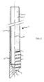
- the anchor 1 has an anchor rod 2 on.
- This is a common threaded rod made of suitable steel, the anchor rod 2 only by cutting an endless threaded rod vertically is generated to their axis in the desired length.
- On the anchor rod 2 is an end nut 3 screwed on from the threaded rod towards its free end 4 has a conical extension section 6, whose length is about 1/8 to 1/4 of the total length of the end nut 3 is.
- the end nut 3 On the outside, the end nut 3 has a helical shape running V-groove 7. At its free end 4 it is one that runs across its entire width Bevel 8, which runs here at 45 ° to axis A, Mistake.
- the end nut 3 has an internal thread 9 on, which corresponds to the external thread 11 of the anchor rod 2 or is adapted.
- the anchor rod 2 is over one part their length with a shrunk-on sleeve 12 suitable material, such as plastic.
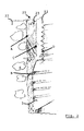
- the anchor 1 is defined basically in a manner known per se. First of all into a borehole 21 (FIG. 2) a conventional composite dowel cartridge, as from DE 41 06 680 A1 or DE 41 32 625 A1 is known, optionally with reinforcing needles, as known from DE 37 41 320 A1, in the Borehole introduced. Then the invention Anchor 1 hammered into the borehole, the Wrapping the composite dowel cartridge is destroyed so that whose adhesive content can leak out and possibly can mix the two components. For the anchor 1 is rotated in the borehole for better mixing, the bevel 8 an optimal mixing of the adhesive components.
- the compound 23 then hardens. There is an intimate adhesive connection between the Concrete 22 and the compound 23 (at A) and between the Compound 23 and the end nut 3 (at B). Farther there is a connection between the compound 23 and the Shrink sleeve 12 (at C). No adhesive bond is created in the illustrated embodiment between the Shrink sleeve 12 and the anchor rod 2 (at D).
- the composite mass penetrates into the grooves 7 of the end nut 3 a. Furthermore, the composite mass falls behind conical area 6 of the end nut 3.
Landscapes
- Engineering & Computer Science (AREA)
- General Engineering & Computer Science (AREA)
- Mechanical Engineering (AREA)
- Joining Of Building Structures In Genera (AREA)
- Dowels (AREA)
Applications Claiming Priority (2)
| Application Number | Priority Date | Filing Date | Title |
|---|---|---|---|
| DE4429055 | 1994-08-16 | ||
| DE4429055A DE4429055A1 (de) | 1994-08-16 | 1994-08-16 | Anker für Beton oder dergleichen |
Publications (2)
| Publication Number | Publication Date |
|---|---|
| EP0697530A1 EP0697530A1 (de) | 1996-02-21 |
| EP0697530B1 true EP0697530B1 (de) | 1998-04-22 |
Family
ID=6525835
Family Applications (1)
| Application Number | Title | Priority Date | Filing Date |
|---|---|---|---|
| EP95111135A Expired - Lifetime EP0697530B1 (de) | 1994-08-16 | 1995-07-15 | Anker für Beton oder dergleichen |
Country Status (3)
| Country | Link |
|---|---|
| EP (1) | EP0697530B1 (ja) |
| JP (1) | JPH08189515A (ja) |
| DE (2) | DE4429055A1 (ja) |
Cited By (2)
| Publication number | Priority date | Publication date | Assignee | Title |
|---|---|---|---|---|
| DE202009014039U1 (de) | 2009-04-04 | 2010-09-02 | B+Btec Export Division Of Dbm Diamant Systemen Bv | Verbundanker mit Glaspatrone für die Zugzone |
| US10112291B2 (en) | 2016-01-20 | 2018-10-30 | Caterpillar Inc. | Tie rod connection for a hydraulic hammer |
Families Citing this family (3)
| Publication number | Priority date | Publication date | Assignee | Title |
|---|---|---|---|---|
| EP1176321A1 (de) | 2000-07-28 | 2002-01-30 | B+Btec BV | Ankersystem |
| DE102012103546A1 (de) * | 2012-04-23 | 2013-10-24 | Johann Moissl | Anker für Wände, zum Befestigen von abragenden Bauwerken wie Markisen |
| DE102012104938A1 (de) * | 2012-06-06 | 2013-12-12 | Johann Moissl | Anker für Wände, zum Befestigen von abragenden Bauwerken wie Markisen |
Family Cites Families (7)
| Publication number | Priority date | Publication date | Assignee | Title |
|---|---|---|---|---|
| NO743043L (ja) * | 1974-08-27 | 1975-03-24 | Fosroc International Ltd | |
| GB2006367B (en) * | 1977-07-28 | 1982-01-27 | Fosroc Ag | Anchoring |
| DE3014078A1 (de) * | 1980-04-12 | 1981-10-15 | BBT-Holding AG, Bösingen | Ankerstab |
| EP0251887B1 (fr) * | 1986-06-24 | 1991-01-09 | Forges Et Boulonneries D'ars-Sur-Moselle | Boulon de soutènement extensible, méthode de soutènement, utilisation du boulon |
| DE3741320A1 (de) | 1987-12-05 | 1989-06-15 | B & Btec Holding Ag | Verfahren zum befestigen von ankerstangen in beton und verbundmasse |
| DE4106680A1 (de) | 1990-08-13 | 1992-02-20 | B & Btec Holding Ag | Klebstoffpatrone fuer einen verbundduebel |
| DE4132625A1 (de) | 1991-10-01 | 1993-04-08 | B & Btec Holding Ag | Klebstoffpatrone fuer einen verbundduebel und verfahren zu ihrer herstellung |
-
1994
- 1994-08-16 DE DE4429055A patent/DE4429055A1/de not_active Withdrawn
-
1995
- 1995-07-15 DE DE59501971T patent/DE59501971D1/de not_active Expired - Fee Related
- 1995-07-15 EP EP95111135A patent/EP0697530B1/de not_active Expired - Lifetime
- 1995-08-15 JP JP7208243A patent/JPH08189515A/ja not_active Abandoned
Cited By (3)
| Publication number | Priority date | Publication date | Assignee | Title |
|---|---|---|---|---|
| DE202009014039U1 (de) | 2009-04-04 | 2010-09-02 | B+Btec Export Division Of Dbm Diamant Systemen Bv | Verbundanker mit Glaspatrone für die Zugzone |
| DE102010013924A1 (de) | 2009-04-04 | 2010-11-18 | B+Btec Export Division Of Dbn Diamant Systemen Bv | Verbundanker mit Glaspatrone für die Zugzone |
| US10112291B2 (en) | 2016-01-20 | 2018-10-30 | Caterpillar Inc. | Tie rod connection for a hydraulic hammer |
Also Published As
| Publication number | Publication date |
|---|---|
| JPH08189515A (ja) | 1996-07-23 |
| DE59501971D1 (de) | 1998-05-28 |
| DE4429055A1 (de) | 1996-02-22 |
| EP0697530A1 (de) | 1996-02-21 |
Similar Documents
| Publication | Publication Date | Title |
|---|---|---|
| DE102010043769B4 (de) | Ankerbaugruppe, insbesondere für den Berg- und Tunnelbau | |
| EP3559484B1 (de) | System zum fügen oder armieren von bauteilen | |
| EP0363779B1 (de) | Vorrichtung zur Verankerung eines stabförmigen Zugglieds aus Faserverbundwerkstoff | |
| EP2257690A1 (de) | Korrosionsgeschützter selbstbohranker sowie ankerteileinheit und verfahren zu dessen herstellung | |
| EP0955476A2 (de) | Selbstschneidende Schraube zum Einsatz in Vollbaustoffen | |
| EP3219442B1 (de) | Antriebselement zur übertragung eines drehmomentes auf eine gewindeeinsatz-hülse | |
| DE2556493A1 (de) | Verankerungsbolzen | |
| EP0251999B1 (de) | Mittels einer aushärtenden Masse verankerbare Ankerstange | |
| DE3910627C2 (ja) | ||
| EP0697530B1 (de) | Anker für Beton oder dergleichen | |
| DE102010043765B4 (de) | Ankerbaugruppe sowie Verfahren zur Herstellung einer Ankerbaugruppe | |
| DE3741320A1 (de) | Verfahren zum befestigen von ankerstangen in beton und verbundmasse | |
| DE4438997B4 (de) | Gebirgsanker | |
| EP0056255A1 (de) | Vorrichtung zum Befestigen von Gegenständen an einer fertigen Betonwand | |
| EP0739442B1 (de) | Verspannbarer gfk-gebirgsanker | |
| EP3808934B1 (de) | Vorspannanker zum sichern einer geologischen formation | |
| DE29519888U1 (de) | Anker für Beton o.dgl. | |
| DE2164666A1 (de) | Ankerbolzen | |
| WO1993010362A1 (de) | Klebeanker | |
| DE29614733U1 (de) | Vorrichtung zur Verankerung von Bewehrungsstäben | |
| DE102017126056A1 (de) | Verfahren zum Befestigen eines Dämmstoffelements und Dämmstoffdübel | |
| DE7730164U1 (ja) | ||
| WO1999007956A1 (de) | Verbindungselement zur verankerung in einem holzwerkstück | |
| DE3631544A1 (de) | Verfahren zum verankern von bauteilen in insbesondere beton | |
| DE29803927U1 (de) | Vorrichtung zur Erstellung eines Verbundankers in hohlen Bauteilen |
Legal Events
| Date | Code | Title | Description |
|---|---|---|---|
| PUAI | Public reference made under article 153(3) epc to a published international application that has entered the european phase |
Free format text: ORIGINAL CODE: 0009012 |
|
| 17P | Request for examination filed |
Effective date: 19951122 |
|
| AK | Designated contracting states |
Kind code of ref document: A1 Designated state(s): CH DE FR GB LI NL |
|
| 17Q | First examination report despatched |
Effective date: 19961001 |
|
| GRAG | Despatch of communication of intention to grant |
Free format text: ORIGINAL CODE: EPIDOS AGRA |
|
| GRAG | Despatch of communication of intention to grant |
Free format text: ORIGINAL CODE: EPIDOS AGRA |
|
| GRAH | Despatch of communication of intention to grant a patent |
Free format text: ORIGINAL CODE: EPIDOS IGRA |
|
| GRAH | Despatch of communication of intention to grant a patent |
Free format text: ORIGINAL CODE: EPIDOS IGRA |
|
| GRAA | (expected) grant |
Free format text: ORIGINAL CODE: 0009210 |
|
| AK | Designated contracting states |
Kind code of ref document: B1 Designated state(s): CH DE FR GB LI NL |
|
| REG | Reference to a national code |
Ref country code: CH Ref legal event code: EP |
|
| REF | Corresponds to: |
Ref document number: 59501971 Country of ref document: DE Date of ref document: 19980528 |
|
| REG | Reference to a national code |
Ref country code: CH Ref legal event code: NV Representative=s name: TROESCH SCHEIDEGGER WERNER AG |
|
| GBT | Gb: translation of ep patent filed (gb section 77(6)(a)/1977) |
Effective date: 19980521 |
|
| ET | Fr: translation filed | ||
| PLBE | No opposition filed within time limit |
Free format text: ORIGINAL CODE: 0009261 |
|
| STAA | Information on the status of an ep patent application or granted ep patent |
Free format text: STATUS: NO OPPOSITION FILED WITHIN TIME LIMIT |
|
| 26N | No opposition filed | ||
| REG | Reference to a national code |
Ref country code: GB Ref legal event code: IF02 |
|
| PGFP | Annual fee paid to national office [announced via postgrant information from national office to epo] |
Ref country code: CH Payment date: 20021011 Year of fee payment: 8 |
|
| PGFP | Annual fee paid to national office [announced via postgrant information from national office to epo] |
Ref country code: GB Payment date: 20030702 Year of fee payment: 9 |
|
| PGFP | Annual fee paid to national office [announced via postgrant information from national office to epo] |
Ref country code: NL Payment date: 20030721 Year of fee payment: 9 |
|
| PGFP | Annual fee paid to national office [announced via postgrant information from national office to epo] |
Ref country code: DE Payment date: 20030723 Year of fee payment: 9 |
|
| PG25 | Lapsed in a contracting state [announced via postgrant information from national office to epo] |
Ref country code: LI Free format text: LAPSE BECAUSE OF NON-PAYMENT OF DUE FEES Effective date: 20030731 Ref country code: CH Free format text: LAPSE BECAUSE OF NON-PAYMENT OF DUE FEES Effective date: 20030731 |
|
| PGFP | Annual fee paid to national office [announced via postgrant information from national office to epo] |
Ref country code: FR Payment date: 20030731 Year of fee payment: 9 |
|
| REG | Reference to a national code |
Ref country code: CH Ref legal event code: PL |
|
| PG25 | Lapsed in a contracting state [announced via postgrant information from national office to epo] |
Ref country code: GB Free format text: LAPSE BECAUSE OF NON-PAYMENT OF DUE FEES Effective date: 20040715 |
|
| PG25 | Lapsed in a contracting state [announced via postgrant information from national office to epo] |
Ref country code: NL Free format text: LAPSE BECAUSE OF NON-PAYMENT OF DUE FEES Effective date: 20050201 Ref country code: DE Free format text: LAPSE BECAUSE OF NON-PAYMENT OF DUE FEES Effective date: 20050201 |
|
| GBPC | Gb: european patent ceased through non-payment of renewal fee |
Effective date: 20040715 |
|
| PG25 | Lapsed in a contracting state [announced via postgrant information from national office to epo] |
Ref country code: FR Free format text: LAPSE BECAUSE OF NON-PAYMENT OF DUE FEES Effective date: 20050331 |
|
| NLV4 | Nl: lapsed or anulled due to non-payment of the annual fee |
Effective date: 20050201 |
|
| REG | Reference to a national code |
Ref country code: FR Ref legal event code: ST |