EP0697530B1 - Anchoring bolt for concrete or similar - Google Patents
Anchoring bolt for concrete or similar Download PDFInfo
- Publication number
- EP0697530B1 EP0697530B1 EP95111135A EP95111135A EP0697530B1 EP 0697530 B1 EP0697530 B1 EP 0697530B1 EP 95111135 A EP95111135 A EP 95111135A EP 95111135 A EP95111135 A EP 95111135A EP 0697530 B1 EP0697530 B1 EP 0697530B1
- Authority
- EP
- European Patent Office
- Prior art keywords
- tie bolt
- anchor
- concrete
- bolt according
- nut
- Prior art date
- Legal status (The legal status is an assumption and is not a legal conclusion. Google has not performed a legal analysis and makes no representation as to the accuracy of the status listed.)
- Expired - Lifetime
Links
- 239000004567 concrete Substances 0.000 title claims description 18
- 238000004873 anchoring Methods 0.000 title description 2
- 239000002131 composite material Substances 0.000 description 14
- 239000000853 adhesive Substances 0.000 description 11
- 230000001070 adhesive effect Effects 0.000 description 11
- 239000004570 mortar (masonry) Substances 0.000 description 6
- KGNDCEVUMONOKF-UGPLYTSKSA-N benzyl n-[(2r)-1-[(2s,4r)-2-[[(2s)-6-amino-1-(1,3-benzoxazol-2-yl)-1,1-dihydroxyhexan-2-yl]carbamoyl]-4-[(4-methylphenyl)methoxy]pyrrolidin-1-yl]-1-oxo-4-phenylbutan-2-yl]carbamate Chemical compound C1=CC(C)=CC=C1CO[C@H]1CN(C(=O)[C@@H](CCC=2C=CC=CC=2)NC(=O)OCC=2C=CC=CC=2)[C@H](C(=O)N[C@@H](CCCCN)C(O)(O)C=2OC3=CC=CC=C3N=2)C1 KGNDCEVUMONOKF-UGPLYTSKSA-N 0.000 description 4
- 229940125833 compound 23 Drugs 0.000 description 4
- 239000000463 material Substances 0.000 description 4
- 229910000831 Steel Inorganic materials 0.000 description 3
- 239000011347 resin Substances 0.000 description 3
- 229920005989 resin Polymers 0.000 description 3
- 239000010959 steel Substances 0.000 description 3
- 230000005540 biological transmission Effects 0.000 description 1
- UHZZMRAGKVHANO-UHFFFAOYSA-M chlormequat chloride Chemical compound [Cl-].C[N+](C)(C)CCCl UHZZMRAGKVHANO-UHFFFAOYSA-M 0.000 description 1
- 150000001875 compounds Chemical class 0.000 description 1
- 230000007797 corrosion Effects 0.000 description 1
- 238000005260 corrosion Methods 0.000 description 1
- 239000003292 glue Substances 0.000 description 1
- 238000004519 manufacturing process Methods 0.000 description 1
- 239000000203 mixture Substances 0.000 description 1
- 230000000149 penetrating effect Effects 0.000 description 1
- 239000011148 porous material Substances 0.000 description 1
- 230000003014 reinforcing effect Effects 0.000 description 1
- 239000011435 rock Substances 0.000 description 1
- 238000007493 shaping process Methods 0.000 description 1
- 239000004575 stone Substances 0.000 description 1
Images
Classifications
-
- F—MECHANICAL ENGINEERING; LIGHTING; HEATING; WEAPONS; BLASTING
- F16—ENGINEERING ELEMENTS AND UNITS; GENERAL MEASURES FOR PRODUCING AND MAINTAINING EFFECTIVE FUNCTIONING OF MACHINES OR INSTALLATIONS; THERMAL INSULATION IN GENERAL
- F16B—DEVICES FOR FASTENING OR SECURING CONSTRUCTIONAL ELEMENTS OR MACHINE PARTS TOGETHER, e.g. NAILS, BOLTS, CIRCLIPS, CLAMPS, CLIPS OR WEDGES; JOINTS OR JOINTING
- F16B13/00—Dowels or other devices fastened in walls or the like by inserting them in holes made therein for that purpose
- F16B13/14—Non-metallic plugs or sleeves; Use of liquid, loose solid or kneadable material therefor
- F16B13/141—Fixing plugs in holes by the use of settable material
- F16B13/143—Fixing plugs in holes by the use of settable material using frangible cartridges or capsules containing the setting components
-
- F—MECHANICAL ENGINEERING; LIGHTING; HEATING; WEAPONS; BLASTING
- F16—ENGINEERING ELEMENTS AND UNITS; GENERAL MEASURES FOR PRODUCING AND MAINTAINING EFFECTIVE FUNCTIONING OF MACHINES OR INSTALLATIONS; THERMAL INSULATION IN GENERAL
- F16B—DEVICES FOR FASTENING OR SECURING CONSTRUCTIONAL ELEMENTS OR MACHINE PARTS TOGETHER, e.g. NAILS, BOLTS, CIRCLIPS, CLAMPS, CLIPS OR WEDGES; JOINTS OR JOINTING
- F16B13/00—Dowels or other devices fastened in walls or the like by inserting them in holes made therein for that purpose
- F16B13/14—Non-metallic plugs or sleeves; Use of liquid, loose solid or kneadable material therefor
- F16B13/141—Fixing plugs in holes by the use of settable material
- F16B2013/148—Means for inhibiting adhesion between dowel or anchor bolt parts and the surrounding grouting composition
Landscapes
- Engineering & Computer Science (AREA)
- General Engineering & Computer Science (AREA)
- Mechanical Engineering (AREA)
- Joining Of Building Structures In Genera (AREA)
- Dowels (AREA)
Description
Die Erfindung betrifft einen Anker für Beton oder dergleichen
nach dem Oberbegriff des Anspruchs 1.The invention relates to an anchor for concrete or the like
according to the preamble of
Die Erfindung bezieht sich auf einen Anker zur Verankerung von Teilen in in Beton, Fels, Gestein oder dergleichen gesetzten Bohrlöchern im Rahmen eines Verbunddübelsystems, wobei der gesetzte Anker insbesondere auf Zug beanspruchbar sein soll, auch wenn der Anker in der Zugzone des Betons montiert wird.The invention relates to an anchor for anchoring of parts in concrete, rock, stone or the like set drill holes as part of a composite dowel system, the anchor being set especially on tension should be loadable, even if the anchor in the Tensile zone of the concrete is mounted.
Die GB-A-1 481 004 zeigt einen Anker für Beton oder dergleichen mit einer Gewinde-Ankerstange und einer auf diese aufgeschraubten üblichen Mehrkantmutter mit einem rechteckigen äußeren Längsschnittprofil. Die Mutter weist über ihre gesamte Länge hin einen konstanten Innendurchmesser im Gewinde auf; sie ist durch eine Plastikkappe an dem dem Einführende für die Gewindestange gegenüberliegenden Ende verschlossen. Die Festlegung der Mutter an der Gewindestange in einem Bohrloch erfolgt durch in dieses eingeführtes Harzmaterial. Die Mutter und damit die Gewindestange werden in dem im Bohrloch einsitzenden Harzmaterial im wesentlichen formschlüssig über die das rückseitige Ende der Mutter bildende Schulter gehalten, wobei das Harzmaterial selbst im Bohrloch an dessen Wandungen reib- und teilweise durch Eindringen in Mikroöffnungen oder Poren auch formschlüssig gehalten wird. Aufgrund der Ausgestaltung des vorgenannten Gegenstandes mit einer kurzen Mutter mit zylindrischem Längsschnittprofil ist es notwendig, die die Mutter und damit die Stange haltende Schulter der Mutter relativ groß auszubilden, d.h. diese mit relativ großem Radius bzw. einer starken Wandung zu versehen, wie dies der Entgegenhaltung zu entnehmen ist. Damit ist es aber notwendig, eine Bohrung mit einem gegenüber dem Durchmesser der Gewindestange selbst relativen großen Durchmesser zu schaffen - beim Stande der Technik beträgt der Durchmesser das Dreifache der Gewindestange.GB-A-1 481 004 shows an anchor for concrete or the like with a threaded anchor rod and one this screwed on usual polygonal nut with a rectangular outer longitudinal section profile. The mother points a constant inner diameter over its entire length in the thread; it is on by a plastic cap opposite to the lead-in for the threaded rod Closed end. Laying down the mother the threaded rod in a borehole is made by in this introduced resin material. The mother and so the threaded rod is in the one sitting in the borehole Resin material essentially form-fitting about the rear end of the mother's shoulder held, the resin material itself in the borehole at its Walls friction and partly by penetrating micro openings or pores are also held positively. Due to the design of the aforementioned subject with a short nut with a cylindrical profile it is necessary that the mother and thus the To train the mother's shoulder holding the shoulder relatively large, i.e. these with a relatively large radius or one strong wall, such as the citation can be seen. But with that it is necessary Bore with a compared to the diameter of the threaded rod to create even relatively large diameters - in the prior art, the diameter is Triple the threaded rod.
Der Erfindung liegt daher die Aufgabe zugrunde, einen Anker für Beton oder dgl. zu schaffen, der einen sicheren Halt bei relativ zu der Stärke der Ankerstange geringerem Bohrlochdurchmesser ermöglicht.The invention is therefore based on the object To create anchors for concrete or the like secure hold relative to the strength of the anchor rod allows a smaller borehole diameter.
Zum Setzen von Ankern mit Zugbelastung wurde schon vorgeschlagen, Bohrlöcher mit einer konischen Hinterschneidung zu versehen. Ein Herstellen eines solchen Bohrloches ist äußerst aufwendig und daher mit hohen Kosten verbunden. Es sind weiter Anker bekannt, die aber als Sonderteile gefertigt werden müssen und daher und aufgrund ihrer speziellen Ausgestaltung mit einem sehr hohen Fertigungsaufwand verbunden sind, der ebenfalls zu sehr hohen Kosten führt, insbesondere wenn diese Anker korrosionsfrei sein sollen. It has already been proposed to set anchors with tensile load Drill holes with a conical undercut to provide. Making such a borehole is extremely complex and therefore associated with high costs. Anchors are also known, but as special parts have to be manufactured and therefore and because of their special design with a very high production cost are connected, which is also very high Cost leads, especially if these anchors are corrosion free should be.
Erfindungsgemäß wird die genannte Aufgabe bei einem Anker
der eingangs genannten Art durch die kennzeichnenden
Merkmale des Anspruchs 1 gelöst.According to the invention, the stated task is for an anchor
of the type mentioned above by the characteristic
Features of
Die Erfindung sieht also eine herkömmliche Gewinde-Ankerstange vor, die durch Ablängen von Endlos-Gewindestangen, vorzugsweise senkrecht zur Achse, hergestellt werden kann und damit äußerst preiswert ist, selbst wenn sie aus korrosionsfreiem Stahl besteht. Zusätzlich ist eine auf die Ankerstange aufgeschraubte, sich von der Ankerstange her zu ihrem eigenen freien Ende konisch erweiternde, ebenfalls vorzugsweise korrosionsfreie Endmutter vorgesehen, die auf ihrer Außenseite eine Profilierung aufweist. Dadurch, daß bei Einsatz dieses Ankers als Verbunddübel, also zusammen mit vorher eingebrachtem Klebstoff oder Mörtel, sich der Klebstoff oder Mörtel vor der erweiterten Endmutter ansammelt und ausgehärtet ist und dabei eine innige Verbindung zunächst mit dem umgebenden Beton eingeht, wird eine zuverlässige kraft- und formschlüssige Festlegung des erfindungsgemäßen Ankers im gebohrten Betonloch sichergestellt. Die Länge des sich erweiternden Bereiches der Endmutter sollte mehr als 1/8 ihrer Gesamtlänge betragen.The invention thus sees a conventional threaded anchor rod before, by cutting endless threaded rods, preferably perpendicular to the axis and is extremely inexpensive, even if it is out corrosion-free steel. In addition, one is on the anchor rod is screwed away from the anchor rod conically widening towards their own free end, also preferably provided a corrosion-free end nut, which has a profile on its outside. The fact that when using this anchor as a composite dowel, So together with previously applied glue or mortar, the adhesive or mortar in front of the enlarged end nut is accumulated and cured and an intimate connection with the surrounding one When concrete comes in, it becomes a reliable non-positive and form-fitting Fixing the anchor according to the invention in drilled concrete hole ensured. The length of yourself expanding area of the end nut should be more than 1/8 their total length.
Die Profilierung ist insbesondere eine schraubenförmig verlaufende Nut, die einen V-förmigen Querschnitt hat. In diese Profilierung kann Mörtel- bzw. Klebstoffmasse vor dem Aushärten eindringen und nach dem Aushärten die formschlüssige Verbindung verstärken.The profile is in particular a helical one running groove, which has a V-shaped cross section. In this profile can pre-mix mortar or adhesive penetrate the curing and after curing the reinforce positive connection.
Eine weitere bevorzugte Ausgestaltung des erfindungsgemäßen Ankers sieht vor, daß die Endmutter an ihrem freien Ende eine Abschrägung aufweist, wobei insbesondere die Abschrägung einen Winkel von 30 bis 60° zur Achse des Ankers einschließt. Hierdurch kann nach Einbringen des Ankers in das Bohrloch, in dem sich schon die Verbunddübelpatrone bzw. der Mörtel oder Klebstoff befindet, durch Drehen des Ankers vor Aushärten des Mörtels/Klebstoffs eine gute Durchmischung, insbesondere wenn ein Zweikomponenten-Klebstoff-System verwendet wird, erzielt werden. Dies ist insbesondere der Fall, wenn die Abschrägung sich über die gesamte Breite der Endmutter erstreckt.Another preferred embodiment of the invention Ankers envisages that the final mother will be at her free End has a bevel, in particular the Bevel an angle of 30 to 60 ° to the axis of the Anchor includes. As a result, after the Anchor in the borehole in which there is already the composite dowel cartridge or the mortar or adhesive is through Turn the anchor before the mortar / adhesive has hardened good mixing, especially when using a two-component adhesive system is used to be achieved. This is especially the case if the bevel is extends over the entire width of the end nut.
Eine weitere bevorzugte Ausgestaltung sieht vor, daß die Ankerstange mit einer aufgeschrumpften Hülle versehen ist. Während die auf den Anker aufgeschrumpfte Hülle sich mit der Mörtelmasse und über diese mit dem Beton verbindet und damit drehfest gehalten wird, ergibt sich durch diese Ausgestaltung keine Klebeverbindung zwischen der Ankerstange im Bereich der Hülle. Die mit der tief im Inneren des Betons in der beschriebenen Weise festgelegten Endmutter durch eine Schraubverbindung verbundene Ankerstange kann also durch Herausschrauben aus der Endmutter entfernt und ausgewechselt werden. Another preferred embodiment provides that the Provide the anchor rod with a shrink-on cover is. While the shell shrunk onto the anchor with the mortar mass and connects it to the concrete and thus held in rotation, results from this configuration no adhesive connection between the Anchor rod in the area of the shell. The one with the deep inside Set the interior of the concrete in the manner described End nut connected by a screw connection The anchor rod can therefore be unscrewed from the End nut removed and replaced.
Insgesamt bietet die Erfindung eine Vielzahl von Vorteilen. Durch die erfindungsgemäße Ausgestaltung eines Ankers mit aufgeschraubter, sich erweiternder Endmutter wird die Belastung tief in den Beton übertragen, während es im vorderen Bereich der Ankerstange keine Klebverbindung derselben mit der Bohrlochwandung gibt, sich dort aber die die formschlüssige Verbindung für die Endmutter gewährleistende ausgehärtete Verbundmasse gebildet hat. Hierdurch wird weiterhin erreicht, daß auch im Falle eines Risses im Beton, auch in der Zugzone, im Bohrloch eine sichere Festlegung und damit hinreichende Übertragung von Traglast gewährleistet bleibt.Overall, the invention offers a number of advantages. Due to the configuration of a Anchor with screwed on, widening end nut the load is transferred deep into the concrete while there is no adhesive connection in the front area of the anchor rod same with the borehole wall, there but that is the positive connection for the end nut ensuring cured composite has formed. This also ensures that even in the case a crack in the concrete, also in the draft zone, in the borehole a secure definition and therefore sufficient transmission of load remains guaranteed.
Der erfindungsgemäße Anker wird im Rahmen eines Verbunddübelsystems eingesetzt, bei dem beispielsweise Verbunddübelpatronen nach der DE 41 06 680 A1, der DE 41 32 625 A1 oder gegebenenfalls mit Verstärkung durch Stahlnadeln nach der DE 37 41 320 A1 verwendet werden; es sind aber grundsätzlich auch andere Verbunddübelpatronen einsetzbar.The anchor according to the invention is part of a composite dowel system used, for example, in composite dowel cartridges according to DE 41 06 680 A1, DE 41 32 625 A1 or, if necessary, reinforced with steel needles can be used according to DE 37 41 320 A1; but there are basically other composite dowel cartridges can also be used.
Weitere Vorteile und Merkmale der Erfindung ergeben sich aus den Ansprüchen und aus der nachfolgenden Beschreibung, in der ein bevorzugtes Ausführungsbeispiel der Erfindung unter Bezugnahme auf die Zeichnung im einzelnen erläutert ist. Dabei zeigt:
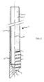
Figur 1- eine Darstellung des erfindungsgemäßen Ankers, teilweise geschnitten; und
Figur 2- eine Darstellung des Einsatzes des erfindungsgemäßen Ankers als Verbunddübel in Beton.
- Figure 1
- a representation of the anchor according to the invention, partially cut; and
- Figure 2
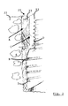
- a representation of the use of the anchor according to the invention as a composite dowel in concrete.
Der erfindungsgemäße Anker 1 weist eine Ankerstange 2
auf. Hierbei handelt es sich um eine übliche Gewindestange
aus geeignetem Stahl, wobei die Ankerstange 2 lediglich
durch Ablängen einer Endlosgewindestange senkrecht
zu ihrer Achse in der gewünschten Länge erzeugt ist. Auf
die Ankerstange 2 ist eine Endmutter 3 aufgeschraubt, die
von der Gewindestange her in Richtung auf ihr freies Ende
4 einen konischen Erweiterungsabschnitt 6 aufweist,
dessen Länge etwa 1/8 bis 1/4 der Gesamtlänge der Endmutter
3 beträgt.The
Auf der Außenseite weist die Endmutter 3 eine schraubenförmig
verlaufende V-Nut 7 auf. An ihrem freien Ende 4
ist sie mit einer über ihre gesamte Breite hin verlaufenden
Abschrägung 8, die hier unter 45° zur Achse A verläuft,
versehen. Die Endmutter 3 weist ein Innengewinde 9
auf, das dem Außengewinde 11 der Ankerstange 2 entspricht
bzw. angepaßt ist. Die Ankerstange 2 ist über einen Teil
ihrer Länge mit einer aufgeschrumpften Hülle 12 aus
geeignetem Material, wie eben Kunststoff, versehen.On the outside, the
Die Festlegung des erfindungsgemäßen Ankers 1 geschieht
grundsätzlich in an sich bekannter Weise. Zunächst wird
in ein Bohrloch 21 (Fig. 2) eine herkömmliche Verbunddübelpatrone,
wie sie aus der DE 41 06 680 A1 oder der DE
41 32 625 A1 bekannt ist, gegebenenfalls mit Verstärkungsnadeln,
wie aus der DE 37 41 320 A1 bekannt, in das
Bohrloch eingebracht. Anschließend wird der erfindungsgemäße
Anker 1 in das Bohrloch eingeschlagen, wobei die
Umhüllung der Verbunddübelpatrone zerstört wird, so daß
deren Klebstoffinhalt austreten kann und sich gegebenenfalls
die beiden Komponenten vermischen können. Zur
besseren Vermischung wird der Anker 1 im Bohrloch gedreht,
wobei die Abschrägung 8 eine optimale Vermischung
der Klebstoffkomponenten bewirkt.The
Anschließend erfolgt das Aushärten der Verbundmasse 23.
Es erfolgt eine innige Klebstoffverbindung zwischen dem
Beton 22 und der Verbundmasse 23 (bei A) und zwischen der
Verbundmasse 23 und der Endmutter 3 (bei B). Weiterhin
erfolgt eine Verbindung zwischen Verbundmasse 23 und der
Schrumpfhülle 12 (bei C). Keine Klebverbindung entsteht
bei dem dargestellten Ausführungsbeispiel zwischen der
Schrumpfhülle 12 und der Ankerstange 2 (bei D).The
Die Verbundmasse dringt dabei in die Nuten 7 der Endmutter
3 ein. Weiterhin hintergreift die Verbundmasse den
konischen Bereich 6 der Endmutter 3.The composite mass penetrates into the
Im ausgehärteten Zustand werden die Lasten von der Ankerstange
über die Endmutter und die Verbunddübelmasse in
den Beton eingetragen. Hierdurch wird die Belastung tief
in das Innere des Betons übertragen, während es im rückwärtigen
oder äußeren Bereich der Ankerstange 3 keine
feste Verbindung zwischen dieser und der Bohrlochwandung
gibt, dieser Bereich aber dennoch durch ausgehärtete,
zylindrische Verbundmasse ausgefüllt ist. Durch die
Formgebung der Endmutter, insbesondere ihren rückwärtigen,
konischen Bereich 6, wird erreicht, daß auch im
Falle eines Risses in der Zugzone des Betons und der
Verbundmasse der Anker weiterhin sicher gehalten wird, so
daß auch bei einem solchen Riß bei der Verwendung des
erfindungsgemäßen Ankers genügend Traglast aufgenommen
werden kann.In the hardened state, the loads from the anchor rod
about the end nut and the composite dowel mass in
entered the concrete. This lowers the load
transferred to the interior of the concrete while it is in the back
or outer area of the
Claims (9)
- Tie bolt for concrete or the like, having a threaded tie rod (2) in the form of a conventional threaded rod and with a nut (3) screwed thereon, characterized in that the nut (3) has conically widening areas (6) extending from its rear end to its free end and has a profiling on its outside.
- Tie bolt according to claim 1, characterized in that the profiling is a helically directed groove (7).
- Tie bolt according to claim 2, characterized in that the groove has a V-shaped cross-section.
- Tie bolt according to one of the preceding claims, characterized in that the free end of the end nut (3) has a bevel (8).
- Tie bolt according to claim 4, characterized in that the bevel (8) forms an angle of 30 to 60° with the axis (A) of the tie bolt (1).
- Tie bolt according to claim 4 or 5, characterized in that the bevel (8) passes over the entire width of the end nut (3).
- Tie bolt according to one of the preceding claims, characterized in that the widening area (6) of the end nut has a length of more than 1/8 of the total length of the end nut (3).
- Tie bolt according to one of the preceding claims, characterized in that the tie rod (2) is provided with a shrunk-on sleeve (12).
- Tie bolt according to one of the preceding claims, characterized in that the tie rod (2) is cut to length transversely with respect to its extension direction (axis A).
Applications Claiming Priority (2)
| Application Number | Priority Date | Filing Date | Title |
|---|---|---|---|
| DE4429055A DE4429055A1 (en) | 1994-08-16 | 1994-08-16 | Anchors for concrete or the like |
| DE4429055 | 1994-08-16 |
Publications (2)
| Publication Number | Publication Date |
|---|---|
| EP0697530A1 EP0697530A1 (en) | 1996-02-21 |
| EP0697530B1 true EP0697530B1 (en) | 1998-04-22 |
Family
ID=6525835
Family Applications (1)
| Application Number | Title | Priority Date | Filing Date |
|---|---|---|---|
| EP95111135A Expired - Lifetime EP0697530B1 (en) | 1994-08-16 | 1995-07-15 | Anchoring bolt for concrete or similar |
Country Status (3)
| Country | Link |
|---|---|
| EP (1) | EP0697530B1 (en) |
| JP (1) | JPH08189515A (en) |
| DE (2) | DE4429055A1 (en) |
Cited By (2)
| Publication number | Priority date | Publication date | Assignee | Title |
|---|---|---|---|---|
| DE202009014039U1 (en) | 2009-04-04 | 2010-09-02 | B+Btec Export Division Of Dbm Diamant Systemen Bv | Composite anchor with glass cartridge for the tensile zone |
| US10112291B2 (en) | 2016-01-20 | 2018-10-30 | Caterpillar Inc. | Tie rod connection for a hydraulic hammer |
Families Citing this family (3)
| Publication number | Priority date | Publication date | Assignee | Title |
|---|---|---|---|---|
| EP1176321A1 (en) | 2000-07-28 | 2002-01-30 | B+Btec BV | Anchoring System |
| DE102012103546A1 (en) * | 2012-04-23 | 2013-10-24 | Johann Moissl | Anchor for fixing at walls of protruding structure e.g. awning, has filling channels guided from front end side of anchor to last profile elevation of outer profile, where channels are diagonally arranged opposite to mantle of anchor body |
| DE102012104938A1 (en) * | 2012-06-06 | 2013-12-12 | Johann Moissl | Anchor for walls, for fixing protruding structures such as awnings |
Family Cites Families (7)
| Publication number | Priority date | Publication date | Assignee | Title |
|---|---|---|---|---|
| NO743043L (en) * | 1974-08-27 | 1975-03-24 | Fosroc International Ltd | |
| GB2006367B (en) * | 1977-07-28 | 1982-01-27 | Fosroc Ag | Anchoring |
| DE3014078A1 (en) * | 1980-04-12 | 1981-10-15 | BBT-Holding AG, Bösingen | Impact-driven masonry anchor bar - has e.g. plastics cap with sharp edge at insertion end and fitted over bar end |
| ES2019647B3 (en) * | 1986-06-24 | 1991-07-01 | Forges Et Boulonneries D'ars-Sur-Moselle | EXTENSIBLE CONTAINMENT BOLT, CONTAINMENT METHOD, USE OF THE BOLT. |
| DE3741320A1 (en) | 1987-12-05 | 1989-06-15 | B & Btec Holding Ag | METHOD FOR FIXING ANCHOR RODS IN CONCRETE AND COMPOSITION |
| DE4106680A1 (en) | 1990-08-13 | 1992-02-20 | B & Btec Holding Ag | ADHESIVE CARTRIDGE FOR A COMPOSITE DOWEL |
| DE4132625A1 (en) | 1991-10-01 | 1993-04-08 | B & Btec Holding Ag | ADHESIVE CARTRIDGE FOR A COMPOSITE DOWEL AND METHOD FOR THEIR PRODUCTION |
-
1994
- 1994-08-16 DE DE4429055A patent/DE4429055A1/en not_active Withdrawn
-
1995
- 1995-07-15 EP EP95111135A patent/EP0697530B1/en not_active Expired - Lifetime
- 1995-07-15 DE DE59501971T patent/DE59501971D1/en not_active Expired - Fee Related
- 1995-08-15 JP JP7208243A patent/JPH08189515A/en not_active Abandoned
Cited By (3)
| Publication number | Priority date | Publication date | Assignee | Title |
|---|---|---|---|---|
| DE202009014039U1 (en) | 2009-04-04 | 2010-09-02 | B+Btec Export Division Of Dbm Diamant Systemen Bv | Composite anchor with glass cartridge for the tensile zone |
| DE102010013924A1 (en) | 2009-04-04 | 2010-11-18 | B+Btec Export Division Of Dbn Diamant Systemen Bv | Shear connector, particularly for anchoring in pressure- and tensile zone in concrete, has anchor rod and glass cartridge which is destructed by anchor rod |
| US10112291B2 (en) | 2016-01-20 | 2018-10-30 | Caterpillar Inc. | Tie rod connection for a hydraulic hammer |
Also Published As
| Publication number | Publication date |
|---|---|
| JPH08189515A (en) | 1996-07-23 |
| DE59501971D1 (en) | 1998-05-28 |
| EP0697530A1 (en) | 1996-02-21 |
| DE4429055A1 (en) | 1996-02-22 |
Similar Documents
| Publication | Publication Date | Title |
|---|---|---|
| DE102010043769B4 (en) | Anchor assembly, especially for mining and tunneling | |
| EP3559484B1 (en) | System for joining or reinforcing components | |
| EP2257690B1 (en) | Corrosion-protected self-drilling anchor and anchor subunit and method for the production thereof | |
| EP0363779B1 (en) | Anchoring device for a tensioning rod composed of a fibre composite | |
| EP0955476A2 (en) | Self-tapping screw for insertion into construction elements | |
| EP3219442B1 (en) | Drive element for transmitting a torque to a thread insert sleeve | |
| DE2556493A1 (en) | Adhesively fixed wall anchor bolt - uses helical web to influence adhesive flow behind outer sealing ring | |
| EP0251999B1 (en) | Anchor bolt anchorable by means of a hardening material | |
| DE3910627C2 (en) | ||
| EP0697530B1 (en) | Anchoring bolt for concrete or similar | |
| DE3741320A1 (en) | METHOD FOR FIXING ANCHOR RODS IN CONCRETE AND COMPOSITION | |
| DE4438997B4 (en) | rock bolts | |
| DE102010043765B4 (en) | Armature assembly and method of making an armature assembly | |
| EP0056255A1 (en) | Device for fixing objects to a concrete wall | |
| EP0739442B1 (en) | Tensionable gfp rock anchor | |
| EP3808934B1 (en) | Pretensioning anchor for securing a geological formation | |
| DE19648931A1 (en) | Anchorage for use in concrete, rock, or similar materials | |
| DE2164666A1 (en) | Anchor bolts | |
| WO1993010362A1 (en) | Roof boolt for imbedding in plastic mortar | |
| DE102017126056A1 (en) | Method for fixing an insulating element and insulating dowels | |
| DE7730164U1 (en) | ||
| WO1999007956A1 (en) | Bonding unit to be fixed in a wood part | |
| DE3631544A1 (en) | Method of anchoring structural parts in, in particular, concrete | |
| EP1176321A1 (en) | Anchoring System | |
| DE102018132968A1 (en) | Expansion dowels |
Legal Events
| Date | Code | Title | Description |
|---|---|---|---|
| PUAI | Public reference made under article 153(3) epc to a published international application that has entered the european phase |
Free format text: ORIGINAL CODE: 0009012 |
|
| 17P | Request for examination filed |
Effective date: 19951122 |
|
| AK | Designated contracting states |
Kind code of ref document: A1 Designated state(s): CH DE FR GB LI NL |
|
| 17Q | First examination report despatched |
Effective date: 19961001 |
|
| GRAG | Despatch of communication of intention to grant |
Free format text: ORIGINAL CODE: EPIDOS AGRA |
|
| GRAG | Despatch of communication of intention to grant |
Free format text: ORIGINAL CODE: EPIDOS AGRA |
|
| GRAH | Despatch of communication of intention to grant a patent |
Free format text: ORIGINAL CODE: EPIDOS IGRA |
|
| GRAH | Despatch of communication of intention to grant a patent |
Free format text: ORIGINAL CODE: EPIDOS IGRA |
|
| GRAA | (expected) grant |
Free format text: ORIGINAL CODE: 0009210 |
|
| AK | Designated contracting states |
Kind code of ref document: B1 Designated state(s): CH DE FR GB LI NL |
|
| REG | Reference to a national code |
Ref country code: CH Ref legal event code: EP |
|
| REF | Corresponds to: |
Ref document number: 59501971 Country of ref document: DE Date of ref document: 19980528 |
|
| REG | Reference to a national code |
Ref country code: CH Ref legal event code: NV Representative=s name: TROESCH SCHEIDEGGER WERNER AG |
|
| GBT | Gb: translation of ep patent filed (gb section 77(6)(a)/1977) |
Effective date: 19980521 |
|
| ET | Fr: translation filed | ||
| PLBE | No opposition filed within time limit |
Free format text: ORIGINAL CODE: 0009261 |
|
| STAA | Information on the status of an ep patent application or granted ep patent |
Free format text: STATUS: NO OPPOSITION FILED WITHIN TIME LIMIT |
|
| 26N | No opposition filed | ||
| REG | Reference to a national code |
Ref country code: GB Ref legal event code: IF02 |
|
| PGFP | Annual fee paid to national office [announced via postgrant information from national office to epo] |
Ref country code: CH Payment date: 20021011 Year of fee payment: 8 |
|
| PGFP | Annual fee paid to national office [announced via postgrant information from national office to epo] |
Ref country code: GB Payment date: 20030702 Year of fee payment: 9 |
|
| PGFP | Annual fee paid to national office [announced via postgrant information from national office to epo] |
Ref country code: NL Payment date: 20030721 Year of fee payment: 9 |
|
| PGFP | Annual fee paid to national office [announced via postgrant information from national office to epo] |
Ref country code: DE Payment date: 20030723 Year of fee payment: 9 |
|
| PG25 | Lapsed in a contracting state [announced via postgrant information from national office to epo] |
Ref country code: LI Free format text: LAPSE BECAUSE OF NON-PAYMENT OF DUE FEES Effective date: 20030731 Ref country code: CH Free format text: LAPSE BECAUSE OF NON-PAYMENT OF DUE FEES Effective date: 20030731 |
|
| PGFP | Annual fee paid to national office [announced via postgrant information from national office to epo] |
Ref country code: FR Payment date: 20030731 Year of fee payment: 9 |
|
| REG | Reference to a national code |
Ref country code: CH Ref legal event code: PL |
|
| PG25 | Lapsed in a contracting state [announced via postgrant information from national office to epo] |
Ref country code: GB Free format text: LAPSE BECAUSE OF NON-PAYMENT OF DUE FEES Effective date: 20040715 |
|
| PG25 | Lapsed in a contracting state [announced via postgrant information from national office to epo] |
Ref country code: NL Free format text: LAPSE BECAUSE OF NON-PAYMENT OF DUE FEES Effective date: 20050201 Ref country code: DE Free format text: LAPSE BECAUSE OF NON-PAYMENT OF DUE FEES Effective date: 20050201 |
|
| GBPC | Gb: european patent ceased through non-payment of renewal fee |
Effective date: 20040715 |
|
| PG25 | Lapsed in a contracting state [announced via postgrant information from national office to epo] |
Ref country code: FR Free format text: LAPSE BECAUSE OF NON-PAYMENT OF DUE FEES Effective date: 20050331 |
|
| NLV4 | Nl: lapsed or anulled due to non-payment of the annual fee |
Effective date: 20050201 |
|
| REG | Reference to a national code |
Ref country code: FR Ref legal event code: ST |