EP0696160A2 - Drain thermique pour composants électriques ou électroniques ayant un plaque de base et des éléments de refroidissement, et procédé de fabrication dudit drain thermique - Google Patents
Drain thermique pour composants électriques ou électroniques ayant un plaque de base et des éléments de refroidissement, et procédé de fabrication dudit drain thermique Download PDFInfo
- Publication number
- EP0696160A2 EP0696160A2 EP95111250A EP95111250A EP0696160A2 EP 0696160 A2 EP0696160 A2 EP 0696160A2 EP 95111250 A EP95111250 A EP 95111250A EP 95111250 A EP95111250 A EP 95111250A EP 0696160 A2 EP0696160 A2 EP 0696160A2
- Authority
- EP
- European Patent Office
- Prior art keywords
- base plate
- profile
- cooling device
- longitudinal grooves
- shaped
- Prior art date
- Legal status (The legal status is an assumption and is not a legal conclusion. Google has not performed a legal analysis and makes no representation as to the accuracy of the status listed.)
- Granted
Links
Images
Classifications
-
- H—ELECTRICITY
- H01—ELECTRIC ELEMENTS
- H01L—SEMICONDUCTOR DEVICES NOT COVERED BY CLASS H10
- H01L23/00—Details of semiconductor or other solid state devices
- H01L23/34—Arrangements for cooling, heating, ventilating or temperature compensation ; Temperature sensing arrangements
- H01L23/36—Selection of materials, or shaping, to facilitate cooling or heating, e.g. heatsinks
- H01L23/367—Cooling facilitated by shape of device
- H01L23/3672—Foil-like cooling fins or heat sinks
-
- H—ELECTRICITY
- H01—ELECTRIC ELEMENTS
- H01L—SEMICONDUCTOR DEVICES NOT COVERED BY CLASS H10
- H01L21/00—Processes or apparatus adapted for the manufacture or treatment of semiconductor or solid state devices or of parts thereof
- H01L21/02—Manufacture or treatment of semiconductor devices or of parts thereof
- H01L21/04—Manufacture or treatment of semiconductor devices or of parts thereof the devices having at least one potential-jump barrier or surface barrier, e.g. PN junction, depletion layer or carrier concentration layer
- H01L21/48—Manufacture or treatment of parts, e.g. containers, prior to assembly of the devices, using processes not provided for in a single one of the subgroups H01L21/06 - H01L21/326
- H01L21/4814—Conductive parts
- H01L21/4871—Bases, plates or heatsinks
- H01L21/4882—Assembly of heatsink parts
-
- H—ELECTRICITY
- H01—ELECTRIC ELEMENTS
- H01L—SEMICONDUCTOR DEVICES NOT COVERED BY CLASS H10
- H01L2924/00—Indexing scheme for arrangements or methods for connecting or disconnecting semiconductor or solid-state bodies as covered by H01L24/00
- H01L2924/0001—Technical content checked by a classifier
- H01L2924/0002—Not covered by any one of groups H01L24/00, H01L24/00 and H01L2224/00
Definitions
- the invention relates to a cooling device for electrical or electronic components of the type mentioned in the preamble of claim 1 and to a method for their production.
- Such a cooling device is already known (EP-A-0 483 058) and has hollow bodies as cooling fins. The production is relatively complex.
- the rib-like cooling elements are made of aluminum plates, each of which is pressed with ends into parallel grooves in the base plate.
- the groove walls have projections and depressions in order to anchor the cooling elements well after they have been pressed into the grooves.
- the production of this heat sink is relatively complex.
- cooling fins are each combined at one end to form a plate, which in turn, for example, with the aid of a thermal paste is connected to the base plate, which has the electronic components, for example semiconductor elements, thyristors.
- the invention has for its object to improve a cooling device of the type mentioned technically and functionally and to simplify manufacture.
- the invention is characterized in claim 1 and particularly preferred embodiments of the same are claimed in subclaims.
- the method according to the invention is characterized in claim 11.
- At least two cooling elements are combined to form a one-piece structural unit;
- This unit consists of a band of the thermally highly conductive material, which is either curved in a meandering or serpentine manner, so that adjacent turns each form rib-like cooling elements, or which forms a U-shaped profile, so that several, in particular a multitude of at least four such U-profiles are arranged in a comb segment-like manner at a distance from one another on one side of the base plate.
- the distance between the profiles is many times smaller than their extension away from the base plate, i.e. as their height.
- a solder-clad strip-shaped sheet metal is preferably used to produce the cooling element assembly, in which the solder with which the assembly is connected to the base plate is already plated as a solder layer on the thermally highly conductive carrier layer, the sheet metal.
- a clad aluminum alloy for example of the AlMn or AlMnMg type, is particularly preferred. Such plated aluminum alloys are particularly suitable for furnace brazing; they are produced primarily by rolling and are given the meandering or serpentine structure for the purposes of the invention by bending. It is advisable to leave the solder layer exposed on the outside of those meandering ends where the connection to the base plate is made.
- the meandering unit In many cases, it is sufficient to place the meandering unit on the side on which the meandering ends are located on the base plate and solder it there, which makes the least effort in terms of production technology and still ensures a good connection and also sufficient heat transfer from the base plate to the meandering unit .
- the meandering band or the profiles can be pressed into the longitudinal grooves of the base plate by means of elongated wire pieces and permanently deformed there and thereby firmly anchored.
- the heat transfer and the anchoring are further improved if the extruded base plate has dovetail-shaped longitudinal grooves in cross section. Pieces of wire are inserted into the wider ends of the dovetail-shaped longitudinal grooves in order to facilitate the connection to the base plate by clamping or wedging in and not only to establish a good mechanical connection, but also to further reduce the thermal contact resistance even without soldering.
- the cooling effect is thereby further improved and an independent loosening of the "profiles" is prevented even when heated up strongly.
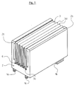
- a number of electronic components 1a, 1b and 1c is attached to a surface of the base plate 2 so that heat developing in the electronic components 1a, 1b and 1c is dissipated well to the base plate 2.
- the base plate 2 is e.g. made of aluminum and forms a profile part with the two side plates 2b, which laterally support the band meandering to the unit 3 made of solder-plated or commercially available aluminum sheet.
- the assembly 3 formed from the strip is inserted and soldered with the meandering ends 3c (according to FIG. 3) bent in an approximately semicircular manner in this example.
- a solder is recommended as a solder which can be soldered quickly and mechanically in terms of production technology and, moreover, forms only a low heat transfer resistance between the base plate 2 and the structural unit 3.
- the electronic components 1a, 1b, 1c can also be arranged on the profile legs of the base plate 2 which act as side plates 2b.
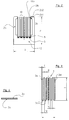
- the aluminum carrier layer 3a of the sheet-like band for the structural unit 3 is coated with a layer thickness of 0.9 mm with a 0.1 mm thick solder layer 3b made of special hard solder, in particular AlSi, on one side.
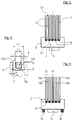
- the structural unit 3 or the U-shaped profiles 13 are anchored in the longitudinal grooves 6 by means of straight, elongated wire pieces 8, as is illustrated in FIG. 8; the elongated wire pieces 8 are clamped between adjacent profile legs 13 of the meandering band or profile 13, in particular by permanent deformation, such that meandering ends 3c (in the area of the "valleys") or the lower parts of the profile legs 13a, 13b in the vicinity of the web part 13c within the longitudinal grooves 6 slightly outwards at an angle of, for example 5 ° widen and lie on the inner surfaces of the dovetail-shaped longitudinal grooves 6.
- the wire pieces 8 are at the bottom of the cross-sectionally U-shaped profile parts 13, i.e. on the web part 13c, clamped between the profile legs 13a and 13b and anchored in the longitudinal grooves 6.
- the upper ends 2b1 of the side plate 2b or side legs are preferably projecting on the inside in order to form contact and contact surfaces 2b2 for the band or the adjacent leg 13b of the profile 13.
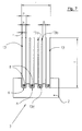
- the cooling element according to the structural unit 3 in FIG. 7 is produced as follows:
- the profile part of the base plate 2 is extruded with the longitudinal grooves 6 made of aluminum, in particular with a dovetail-shaped cross-section (FIG. 8).
- the 4 U-shaped profiles 13 are then inserted into the longitudinal grooves 6 with their bottom or end having the web part 13c.
- pieces of wire 8 with a rectangular cross-section in particular are inserted into the spaces between the profile legs 13a, 13b and expediently by means of a common tool, e.g. in a press, to the bottom, i.e. Web part 13, the profiles 13 inserted; they must overcome a force or are so strongly pressed and pressed, whereby the adjacent parts of the profile legs 13a, 13b are permanently deformed and lie flat on the side walls of the longitudinal grooves 6 with clamping action.
- the profiles can not only be made of aluminum sheet as mentioned above; copper sheet or other thermally highly conductive materials are also well suited. Likewise, copper is also suitable for the wire pieces 8 in addition to aluminum; Alloys with other or different materials can also be used.
Applications Claiming Priority (3)
| Application Number | Priority Date | Filing Date | Title |
|---|---|---|---|
| DE9412460U DE9412460U1 (de) | 1994-08-02 | 1994-08-02 | Kühlvorrichtung für elektrische bzw. elektronische Bauelemente mit einer Grundplatte und mit Kühlelementen |
| DE9412460U | 1994-08-02 | ||
| US08/769,547 US5791406A (en) | 1994-08-02 | 1996-12-19 | Cooling device for electrical or electronic components having a base plate and cooling elements and method for manufacturing the same |
Publications (3)
| Publication Number | Publication Date |
|---|---|
| EP0696160A2 true EP0696160A2 (fr) | 1996-02-07 |
| EP0696160A3 EP0696160A3 (fr) | 1996-03-13 |
| EP0696160B1 EP0696160B1 (fr) | 1997-08-20 |
Family
ID=25962307
Family Applications (1)
| Application Number | Title | Priority Date | Filing Date |
|---|---|---|---|
| EP95111250A Expired - Lifetime EP0696160B1 (fr) | 1994-08-02 | 1995-07-18 | Drain thermique pour composants électriques ou électroniques et procédé de fabrication dudit drain thermique |
Country Status (3)
| Country | Link |
|---|---|
| EP (1) | EP0696160B1 (fr) |
| AT (1) | ATE157212T1 (fr) |
| DE (2) | DE9412460U1 (fr) |
Cited By (4)
| Publication number | Priority date | Publication date | Assignee | Title |
|---|---|---|---|---|
| EP0902469A2 (fr) * | 1997-08-28 | 1999-03-17 | Hoogovens Aluminium Profiltechnik Bonn GmbH | Dispositif de refroidissement pour dispositifs électriques ou électroniques |
| DE10065470A1 (de) * | 2000-12-28 | 2002-07-11 | Corus Aluminium Profiltechnik | Kühlelement für elektrische oder elektronische bauelemente und Verfahren zu dessen Herstellung |
| DE10056387B4 (de) * | 2000-11-14 | 2008-11-13 | Corus Aluminium Profiltechnik Gmbh | Kühlvorrichtung und Verfahren zu deren Herstellung sowie Vorrichtung zur Durchführung des Verfahrens |
| EP2770253A1 (fr) * | 2013-02-26 | 2014-08-27 | Showa Denko K.K. | Appareil de rayonnement de chaleur pour éclairage à DEL |
Families Citing this family (3)
| Publication number | Priority date | Publication date | Assignee | Title |
|---|---|---|---|---|
| ATE330329T1 (de) * | 1996-01-31 | 2006-07-15 | Alcan Tech & Man Ag | Kühlkörper für halbleiterbauelemente od. dgl. |
| DE19700432A1 (de) * | 1997-01-10 | 1998-07-16 | Swg Metallverarbeitung Und Mon | Verfahren zum Herstellen von Kühlkörpern sowie nach dem Verfahren hergestellte Kühlkörper |
| DE19845374C2 (de) * | 1998-10-02 | 2003-01-02 | Swg Metallverarbeitung Und Mon | Verfahren zum Herstellen von Kühlkörpern für elektrische und/oder elektronische Bauteile |
Citations (9)
| Publication number | Priority date | Publication date | Assignee | Title |
|---|---|---|---|---|
| US1830375A (en) | 1930-04-04 | 1931-11-03 | Shoop Gertrude | Heat exchange article |
| DE2502472A1 (de) | 1975-01-22 | 1976-07-29 | Siemens Ag | Kuehlkoerper zur kuehlung von thyristoren |
| EP0123795A2 (fr) | 1983-04-29 | 1984-11-07 | International Business Machines Corporation | Dissipateur de chaleur d'une seule pièce pour un module de dispositif électronique |
| DE3518310A1 (de) | 1985-05-22 | 1986-11-27 | Aluminium-Walzwerke Singen Gmbh, 7700 Singen | Kuehlkoerper fuer halbleiterbauelemente und verfahren zu seiner herstellung |
| WO1987002443A1 (fr) | 1985-10-11 | 1987-04-23 | Neste Oy | Organe de transfert de chaleur et son procede de fabrication |
| DE4106437A1 (de) | 1990-02-28 | 1991-08-29 | Hitachi Ltd | Vorrichtung zur kuehlung von lsi-schaltungen und vorrichtung zur kuehlung eines computers |
| EP0483058A1 (fr) | 1990-10-24 | 1992-04-29 | Alusuisse-Lonza Services Ag | Refroidisseur pour composants semi-conducteurs |
| DE9214061U1 (fr) | 1992-10-17 | 1992-12-24 | Ets Claude Kremer S.A.R.L., Vianden, Li | |
| DE9302754U1 (fr) | 1993-02-25 | 1993-04-15 | Hwang Piin Co. Ltd., Lu Jou Hsiang, Taipeh, Tw |
Family Cites Families (7)
| Publication number | Priority date | Publication date | Assignee | Title |
|---|---|---|---|---|
| GB885150A (en) * | 1959-03-24 | 1961-12-20 | Gallay Ltd | Improvements in or relating to heat exchangers |
| DE3703873A1 (de) * | 1987-02-07 | 1988-08-18 | Sueddeutsche Kuehler Behr | Kuehlkoerper, insbesondere zum kuehlen elektronischer bauelemente |
| JP3122173B2 (ja) * | 1990-11-09 | 2001-01-09 | 株式会社東芝 | 放熱器、放熱装置および放熱器の製造方法 |
| DE4134929A1 (de) * | 1991-10-23 | 1993-04-29 | Vaw Ver Aluminium Werke Ag | Verbundkoerper |
| DE9215145U1 (fr) * | 1992-08-14 | 1993-01-21 | Hoogovens Aluminium Profiltechnik Gmbh, 7981 Vogt, De | |
| JPH06244328A (ja) * | 1993-02-19 | 1994-09-02 | Fujitsu Ltd | ヒートシンク |
| DE9409517U1 (de) * | 1994-06-13 | 1994-07-28 | Siemens Ag | Kühlkörper |
-
1994
- 1994-08-02 DE DE9412460U patent/DE9412460U1/de not_active Expired - Lifetime
-
1995
- 1995-07-18 EP EP95111250A patent/EP0696160B1/fr not_active Expired - Lifetime
- 1995-07-18 AT AT95111250T patent/ATE157212T1/de active
- 1995-07-18 DE DE59500529T patent/DE59500529D1/de not_active Expired - Lifetime
Patent Citations (9)
| Publication number | Priority date | Publication date | Assignee | Title |
|---|---|---|---|---|
| US1830375A (en) | 1930-04-04 | 1931-11-03 | Shoop Gertrude | Heat exchange article |
| DE2502472A1 (de) | 1975-01-22 | 1976-07-29 | Siemens Ag | Kuehlkoerper zur kuehlung von thyristoren |
| EP0123795A2 (fr) | 1983-04-29 | 1984-11-07 | International Business Machines Corporation | Dissipateur de chaleur d'une seule pièce pour un module de dispositif électronique |
| DE3518310A1 (de) | 1985-05-22 | 1986-11-27 | Aluminium-Walzwerke Singen Gmbh, 7700 Singen | Kuehlkoerper fuer halbleiterbauelemente und verfahren zu seiner herstellung |
| WO1987002443A1 (fr) | 1985-10-11 | 1987-04-23 | Neste Oy | Organe de transfert de chaleur et son procede de fabrication |
| DE4106437A1 (de) | 1990-02-28 | 1991-08-29 | Hitachi Ltd | Vorrichtung zur kuehlung von lsi-schaltungen und vorrichtung zur kuehlung eines computers |
| EP0483058A1 (fr) | 1990-10-24 | 1992-04-29 | Alusuisse-Lonza Services Ag | Refroidisseur pour composants semi-conducteurs |
| DE9214061U1 (fr) | 1992-10-17 | 1992-12-24 | Ets Claude Kremer S.A.R.L., Vianden, Li | |
| DE9302754U1 (fr) | 1993-02-25 | 1993-04-15 | Hwang Piin Co. Ltd., Lu Jou Hsiang, Taipeh, Tw |
Cited By (6)
| Publication number | Priority date | Publication date | Assignee | Title |
|---|---|---|---|---|
| EP0902469A2 (fr) * | 1997-08-28 | 1999-03-17 | Hoogovens Aluminium Profiltechnik Bonn GmbH | Dispositif de refroidissement pour dispositifs électriques ou électroniques |
| EP0902469A3 (fr) * | 1997-08-28 | 1999-07-28 | Hoogovens Aluminium Profiltechnik Bonn GmbH | Dispositif de refroidissement pour dispositifs électriques ou électroniques |
| DE10056387B4 (de) * | 2000-11-14 | 2008-11-13 | Corus Aluminium Profiltechnik Gmbh | Kühlvorrichtung und Verfahren zu deren Herstellung sowie Vorrichtung zur Durchführung des Verfahrens |
| DE10065470A1 (de) * | 2000-12-28 | 2002-07-11 | Corus Aluminium Profiltechnik | Kühlelement für elektrische oder elektronische bauelemente und Verfahren zu dessen Herstellung |
| DE10065470B4 (de) * | 2000-12-28 | 2011-02-17 | Aleris Aluminum Vogt Gmbh | Verfahren zur Herstellung eines Kühlelements für elektrische, insbesondere elektronische, Bauelemente |
| EP2770253A1 (fr) * | 2013-02-26 | 2014-08-27 | Showa Denko K.K. | Appareil de rayonnement de chaleur pour éclairage à DEL |
Also Published As
| Publication number | Publication date |
|---|---|
| DE59500529D1 (de) | 1997-09-25 |
| ATE157212T1 (de) | 1997-09-15 |
| EP0696160B1 (fr) | 1997-08-20 |
| EP0696160A3 (fr) | 1996-03-13 |
| DE9412460U1 (de) | 1995-12-14 |
Similar Documents
| Publication | Publication Date | Title |
|---|---|---|
| DE4427854C2 (de) | Kühlvorrichtung und Montageverfahren dafür | |
| DE2502472C2 (de) | Kühlkörper für Thyristoren | |
| DE2813968C2 (de) | Halbleiteranordnung | |
| EP0278240A2 (fr) | Radiateur, en particulier pour le refroidissement de composants électroniques | |
| DE2639979C3 (de) | Halbleiterbaueinheit | |
| EP0490210B1 (fr) | Echangeur de chaleur | |
| EP0805492A2 (fr) | Substrat métal céramique cintré en voûte | |
| WO2003053118A2 (fr) | Dispositif de refroidissement pour puce, et procede de realisation | |
| EP0696160B1 (fr) | Drain thermique pour composants électriques ou électroniques et procédé de fabrication dudit drain thermique | |
| DE2460631C3 (de) | Kuhlkörper zur Fremdkuhlung von Thyristoren | |
| EP0106262B1 (fr) | Echangeur thermique en particulier radiateur | |
| DE19715540C2 (de) | Verfahren zum Herstellen eines gewölbten Metall-Keramik-Substrates | |
| DE10103084B4 (de) | Halbleitermodul und Verfahren zu seiner Herstellung | |
| EP1309037A2 (fr) | Dispositif pour contacter électriquement une portion électroconductive d'un corps allongé, notamment d'un tube ou d'un câble | |
| DE2930044A1 (de) | Bauteil. | |
| DE3625238C2 (fr) | ||
| DE1916554B2 (de) | Verfahren zum Herstellen von Halbleitergleichrichteranordnungen | |
| DE2539856A1 (de) | Plattenheizkoerper | |
| DE20309856U1 (de) | Kühlkörper für Bauelemente | |
| WO1996034245A1 (fr) | Tube plat a cavites multiples pour echangeurs de chaleur et son procede de fabrication | |
| DE1800192B2 (de) | Verfahren zum serienmäßigen Herstellen von Halbleiteranordnungen und Verwendung des Verfahrens zur Kontaktierung scheibenförmiger Halbleiterkörper Aren: Telefunken Patentverwertungsgesellschaft mbH, 7900 Ulm | |
| DE2448618C3 (de) | Flachheizkörper | |
| DE3916788C2 (fr) | ||
| DE10338041B3 (de) | Elektrischer Widerstand und Verfahren zum Herstellen von Widerständen | |
| DE2515356C3 (de) | Elektronenstrahlauffänger für Elektronenstrahlröhren hoher Leistung, insbesondere Hochleistungswanderfeldröhren und Verfahren zu seiner Herstellung |
Legal Events
| Date | Code | Title | Description |
|---|---|---|---|
| PUAI | Public reference made under article 153(3) epc to a published international application that has entered the european phase |
Free format text: ORIGINAL CODE: 0009012 |
|
| PUAL | Search report despatched |
Free format text: ORIGINAL CODE: 0009013 |
|
| AK | Designated contracting states |
Kind code of ref document: A2 Designated state(s): AT CH DE FR GB IT LI |
|
| AK | Designated contracting states |
Kind code of ref document: A3 Designated state(s): AT CH DE FR GB IT LI |
|
| 17P | Request for examination filed |
Effective date: 19960418 |
|
| 17Q | First examination report despatched |
Effective date: 19960710 |
|
| GRAG | Despatch of communication of intention to grant |
Free format text: ORIGINAL CODE: EPIDOS AGRA |
|
| GRAH | Despatch of communication of intention to grant a patent |
Free format text: ORIGINAL CODE: EPIDOS IGRA |
|
| GRAH | Despatch of communication of intention to grant a patent |
Free format text: ORIGINAL CODE: EPIDOS IGRA |
|
| ITF | It: translation for a ep patent filed |
Owner name: STUDIO FERRARIO |
|
| GRAA | (expected) grant |
Free format text: ORIGINAL CODE: 0009210 |
|
| AK | Designated contracting states |
Kind code of ref document: B1 Designated state(s): AT CH DE FR GB IT LI |
|
| REF | Corresponds to: |
Ref document number: 157212 Country of ref document: AT Date of ref document: 19970915 Kind code of ref document: T |
|
| ET | Fr: translation filed | ||
| REG | Reference to a national code |
Ref country code: CH Ref legal event code: NV Representative=s name: GERHARD H. ULRICH PATENTANWALT Ref country code: CH Ref legal event code: EP |
|
| GBT | Gb: translation of ep patent filed (gb section 77(6)(a)/1977) |
Effective date: 19970820 |
|
| REF | Corresponds to: |
Ref document number: 59500529 Country of ref document: DE Date of ref document: 19970925 |
|
| PLBE | No opposition filed within time limit |
Free format text: ORIGINAL CODE: 0009261 |
|
| STAA | Information on the status of an ep patent application or granted ep patent |
Free format text: STATUS: NO OPPOSITION FILED WITHIN TIME LIMIT |
|
| 26N | No opposition filed | ||
| REG | Reference to a national code |
Ref country code: GB Ref legal event code: IF02 |
|
| REG | Reference to a national code |
Ref country code: CH Ref legal event code: NV Representative=s name: AMMANN PATENTANWAELTE AG BERN, CH |
|
| PGFP | Annual fee paid to national office [announced via postgrant information from national office to epo] |
Ref country code: DE Payment date: 20140610 Year of fee payment: 20 Ref country code: CH Payment date: 20140722 Year of fee payment: 20 |
|
| PGFP | Annual fee paid to national office [announced via postgrant information from national office to epo] |
Ref country code: AT Payment date: 20140620 Year of fee payment: 20 Ref country code: FR Payment date: 20140724 Year of fee payment: 20 Ref country code: GB Payment date: 20140721 Year of fee payment: 20 |
|
| PGFP | Annual fee paid to national office [announced via postgrant information from national office to epo] |
Ref country code: IT Payment date: 20140724 Year of fee payment: 20 |
|
| REG | Reference to a national code |
Ref country code: DE Ref legal event code: R071 Ref document number: 59500529 Country of ref document: DE |
|
| REG | Reference to a national code |
Ref country code: CH Ref legal event code: PL |
|
| REG | Reference to a national code |
Ref country code: GB Ref legal event code: PE20 Expiry date: 20150717 |
|
| REG | Reference to a national code |
Ref country code: AT Ref legal event code: MK07 Ref document number: 157212 Country of ref document: AT Kind code of ref document: T Effective date: 20150718 |
|
| PG25 | Lapsed in a contracting state [announced via postgrant information from national office to epo] |
Ref country code: GB Free format text: LAPSE BECAUSE OF EXPIRATION OF PROTECTION Effective date: 20150717 |