EP0696160A2 - Cooling device for electrical or electronic components having a main board and cooling elements, and method for making the same - Google Patents
Cooling device for electrical or electronic components having a main board and cooling elements, and method for making the same Download PDFInfo
- Publication number
- EP0696160A2 EP0696160A2 EP95111250A EP95111250A EP0696160A2 EP 0696160 A2 EP0696160 A2 EP 0696160A2 EP 95111250 A EP95111250 A EP 95111250A EP 95111250 A EP95111250 A EP 95111250A EP 0696160 A2 EP0696160 A2 EP 0696160A2
- Authority
- EP
- European Patent Office
- Prior art keywords
- base plate
- profile
- cooling device
- longitudinal grooves
- shaped
- Prior art date
- Legal status (The legal status is an assumption and is not a legal conclusion. Google has not performed a legal analysis and makes no representation as to the accuracy of the status listed.)
- Granted
Links
Images
Classifications
-
- H—ELECTRICITY
- H01—ELECTRIC ELEMENTS
- H01L—SEMICONDUCTOR DEVICES NOT COVERED BY CLASS H10
- H01L23/00—Details of semiconductor or other solid state devices
- H01L23/34—Arrangements for cooling, heating, ventilating or temperature compensation ; Temperature sensing arrangements
- H01L23/36—Selection of materials, or shaping, to facilitate cooling or heating, e.g. heatsinks
- H01L23/367—Cooling facilitated by shape of device
- H01L23/3672—Foil-like cooling fins or heat sinks
-
- H—ELECTRICITY
- H01—ELECTRIC ELEMENTS
- H01L—SEMICONDUCTOR DEVICES NOT COVERED BY CLASS H10
- H01L21/00—Processes or apparatus adapted for the manufacture or treatment of semiconductor or solid state devices or of parts thereof
- H01L21/02—Manufacture or treatment of semiconductor devices or of parts thereof
- H01L21/04—Manufacture or treatment of semiconductor devices or of parts thereof the devices having at least one potential-jump barrier or surface barrier, e.g. PN junction, depletion layer or carrier concentration layer
- H01L21/48—Manufacture or treatment of parts, e.g. containers, prior to assembly of the devices, using processes not provided for in a single one of the subgroups H01L21/06 - H01L21/326
- H01L21/4814—Conductive parts
- H01L21/4871—Bases, plates or heatsinks
- H01L21/4882—Assembly of heatsink parts
-
- H—ELECTRICITY
- H01—ELECTRIC ELEMENTS
- H01L—SEMICONDUCTOR DEVICES NOT COVERED BY CLASS H10
- H01L2924/00—Indexing scheme for arrangements or methods for connecting or disconnecting semiconductor or solid-state bodies as covered by H01L24/00
- H01L2924/0001—Technical content checked by a classifier
- H01L2924/0002—Not covered by any one of groups H01L24/00, H01L24/00 and H01L2224/00
Definitions
- the invention relates to a cooling device for electrical or electronic components of the type mentioned in the preamble of claim 1 and to a method for their production.
- Such a cooling device is already known (EP-A-0 483 058) and has hollow bodies as cooling fins. The production is relatively complex.
- the rib-like cooling elements are made of aluminum plates, each of which is pressed with ends into parallel grooves in the base plate.
- the groove walls have projections and depressions in order to anchor the cooling elements well after they have been pressed into the grooves.
- the production of this heat sink is relatively complex.
- cooling fins are each combined at one end to form a plate, which in turn, for example, with the aid of a thermal paste is connected to the base plate, which has the electronic components, for example semiconductor elements, thyristors.
- the invention has for its object to improve a cooling device of the type mentioned technically and functionally and to simplify manufacture.
- the invention is characterized in claim 1 and particularly preferred embodiments of the same are claimed in subclaims.
- the method according to the invention is characterized in claim 11.
- At least two cooling elements are combined to form a one-piece structural unit;
- This unit consists of a band of the thermally highly conductive material, which is either curved in a meandering or serpentine manner, so that adjacent turns each form rib-like cooling elements, or which forms a U-shaped profile, so that several, in particular a multitude of at least four such U-profiles are arranged in a comb segment-like manner at a distance from one another on one side of the base plate.
- the distance between the profiles is many times smaller than their extension away from the base plate, i.e. as their height.
- a solder-clad strip-shaped sheet metal is preferably used to produce the cooling element assembly, in which the solder with which the assembly is connected to the base plate is already plated as a solder layer on the thermally highly conductive carrier layer, the sheet metal.
- a clad aluminum alloy for example of the AlMn or AlMnMg type, is particularly preferred. Such plated aluminum alloys are particularly suitable for furnace brazing; they are produced primarily by rolling and are given the meandering or serpentine structure for the purposes of the invention by bending. It is advisable to leave the solder layer exposed on the outside of those meandering ends where the connection to the base plate is made.
- the meandering unit In many cases, it is sufficient to place the meandering unit on the side on which the meandering ends are located on the base plate and solder it there, which makes the least effort in terms of production technology and still ensures a good connection and also sufficient heat transfer from the base plate to the meandering unit .
- the meandering band or the profiles can be pressed into the longitudinal grooves of the base plate by means of elongated wire pieces and permanently deformed there and thereby firmly anchored.
- the heat transfer and the anchoring are further improved if the extruded base plate has dovetail-shaped longitudinal grooves in cross section. Pieces of wire are inserted into the wider ends of the dovetail-shaped longitudinal grooves in order to facilitate the connection to the base plate by clamping or wedging in and not only to establish a good mechanical connection, but also to further reduce the thermal contact resistance even without soldering.
- the cooling effect is thereby further improved and an independent loosening of the "profiles" is prevented even when heated up strongly.
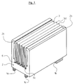
- a number of electronic components 1a, 1b and 1c is attached to a surface of the base plate 2 so that heat developing in the electronic components 1a, 1b and 1c is dissipated well to the base plate 2.
- the base plate 2 is e.g. made of aluminum and forms a profile part with the two side plates 2b, which laterally support the band meandering to the unit 3 made of solder-plated or commercially available aluminum sheet.
- the assembly 3 formed from the strip is inserted and soldered with the meandering ends 3c (according to FIG. 3) bent in an approximately semicircular manner in this example.
- a solder is recommended as a solder which can be soldered quickly and mechanically in terms of production technology and, moreover, forms only a low heat transfer resistance between the base plate 2 and the structural unit 3.
- the electronic components 1a, 1b, 1c can also be arranged on the profile legs of the base plate 2 which act as side plates 2b.
- the aluminum carrier layer 3a of the sheet-like band for the structural unit 3 is coated with a layer thickness of 0.9 mm with a 0.1 mm thick solder layer 3b made of special hard solder, in particular AlSi, on one side.
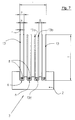
- the structural unit 3 or the U-shaped profiles 13 are anchored in the longitudinal grooves 6 by means of straight, elongated wire pieces 8, as is illustrated in FIG. 8; the elongated wire pieces 8 are clamped between adjacent profile legs 13 of the meandering band or profile 13, in particular by permanent deformation, such that meandering ends 3c (in the area of the "valleys") or the lower parts of the profile legs 13a, 13b in the vicinity of the web part 13c within the longitudinal grooves 6 slightly outwards at an angle of, for example 5 ° widen and lie on the inner surfaces of the dovetail-shaped longitudinal grooves 6.
- the wire pieces 8 are at the bottom of the cross-sectionally U-shaped profile parts 13, i.e. on the web part 13c, clamped between the profile legs 13a and 13b and anchored in the longitudinal grooves 6.
- the upper ends 2b1 of the side plate 2b or side legs are preferably projecting on the inside in order to form contact and contact surfaces 2b2 for the band or the adjacent leg 13b of the profile 13.
- the cooling element according to the structural unit 3 in FIG. 7 is produced as follows:
- the profile part of the base plate 2 is extruded with the longitudinal grooves 6 made of aluminum, in particular with a dovetail-shaped cross-section (FIG. 8).
- the 4 U-shaped profiles 13 are then inserted into the longitudinal grooves 6 with their bottom or end having the web part 13c.
- pieces of wire 8 with a rectangular cross-section in particular are inserted into the spaces between the profile legs 13a, 13b and expediently by means of a common tool, e.g. in a press, to the bottom, i.e. Web part 13, the profiles 13 inserted; they must overcome a force or are so strongly pressed and pressed, whereby the adjacent parts of the profile legs 13a, 13b are permanently deformed and lie flat on the side walls of the longitudinal grooves 6 with clamping action.
- the profiles can not only be made of aluminum sheet as mentioned above; copper sheet or other thermally highly conductive materials are also well suited. Likewise, copper is also suitable for the wire pieces 8 in addition to aluminum; Alloys with other or different materials can also be used.
Abstract
Description
Die Erfindung bezieht sich auf eine Kühlvorrichtung für elektrische bzw. elektronische Bauelemente der im Oberbegriff des Anspruches 1 genannten Gattung sowie auf ein Verfahren zu deren Herstellung.The invention relates to a cooling device for electrical or electronic components of the type mentioned in the preamble of
Eine derartige Kühlvorrichtung ist bereits bekannt (EP-A-0 483 058) und weist Hohlkörper als Kühlrippen auf. Die Herstellung ist relativ aufwendig.Such a cooling device is already known (EP-A-0 483 058) and has hollow bodies as cooling fins. The production is relatively complex.
Eine weitere Kühlvorrichtung ist aus der DE-PS 25 02 472 bekannt. Dabei sind die rippenartigen Kühlelemente aus Aluminiumplatten hergestellt, welche jeweils mit Enden in parallel verlaufende Nuten der Grundplatte eingepreßt sind. Die Nutenwandungen weisen Vorsprünge und Vertiefungen auf, um die Kühlelemente nach dem Einpressen in die Nuten gut zu verankern. Das Herstellen dieses Kühlkörpers ist verhältnismäßig aufwendig.Another cooling device is known from DE-PS 25 02 472. The rib-like cooling elements are made of aluminum plates, each of which is pressed with ends into parallel grooves in the base plate. The groove walls have projections and depressions in order to anchor the cooling elements well after they have been pressed into the grooves. The production of this heat sink is relatively complex.
Darüber hinaus ist es bekannt (DE-PS 35 18 310 und EP-OS 0 483 058), die einzelnen rippenartigen Kühlelemente dadurch fest in der Grundplatte zu verankern, daß die Zwischenstege zwischen den Nuten in der Grundplatte nach dem Einsetzen der Enden der Kühlelemente an die Kühlelementewandung angepreßt werden, wodurch sich die Breite der Nuten verringert. Hier wird empfohlen, die Außenflächen der plattenförmigen bzw. als Hohlkörper ausgebildeten Kühlelemente mit Erhöhungen und Vertiefungen zu versehen, um die Verankerung der einzelnen Kühlelemente in der Grundplatte zu verbessern.In addition, it is known (DE-PS 35 18 310 and EP-
Ferner ist es bekannt (DE-OS 41 06 437), Kühlelemente aus dünnen Drähten herzustellen. Die einzelnen Drähte werden mäanderförmig gebogen, so daß ein und derselbe Draht jeweils Bestandteil einer Vielzahl von Kühlelementen bildet; dabei ist eine Vielzahl solcher Drähte hintereinander angeordnet, um rippenartige Strukturen zu formen. Die Verbindung der dünnen Drähte mit der Grundplatte erfolgt mittels einer metallischen Verbindung. Dabei ist es auch bekannt, eine Kühlmittelströmung von oben auf die rippenförmige Struktur bestehend aus den vielen Kühldrähten aufzublasen.Furthermore, it is known (DE-OS 41 06 437) to produce cooling elements from thin wires. The individual wires become meandering bent so that one and the same wire forms part of a plurality of cooling elements; a large number of such wires are arranged one behind the other to form rib-like structures. The thin wires are connected to the base plate by means of a metallic connection. It is also known to inflate a coolant flow from above onto the rib-shaped structure consisting of the many cooling wires.
Ferner ist es bekannt (EP-PS 0 123 795), aus einem quaderförmigen Block einzelne im Querschnitt wiederum quaderförmige Kühlelemente durch kreuzweises Ausfräsen herzustellen. Der Block wird von beiden Stirnseiten her so mit Fräsrillen versehen, daß sich ein im Querschnitt mäanderartiger Verlauf des verbliebenen Werkstückmaterials ergibt. Auch hier ist der Herstellungsaufwand verhältnismäßig groß.Furthermore, it is known (EP-
Außerdem ist es auch bekannt (DE-GM 92 14 061 und 93 02 754), die Kühlelemente zu einer Baueinheit zusammen zu fassen, indem die Kühlrippen jeweils an einem Ende zu einer Platte zusammen-gefaßt sind, die ihrerseits beispielsweise mit Hilfe einer Wärmeleitpaste mit der Grundplatte in Verbindung steht, welche die elektronischen Bauelemente, beispielsweise Halbleiterelemente, Thyristoren, aufweist.In addition, it is also known (DE-GM 92 14 061 and 93 02 754) to combine the cooling elements to form a structural unit, in that the cooling fins are each combined at one end to form a plate, which in turn, for example, with the aid of a thermal paste is connected to the base plate, which has the electronic components, for example semiconductor elements, thyristors.
Ferner ist es bekannt (US-A-1 830 375), an beiden Außenseiten eines flachen Hohlrohres bandförmige Mäander anzusetzen und mittels einer Drahtwendel festzuhalten.Furthermore, it is known (US-A-1 830 375) to apply band-shaped meanders to both outer sides of a flat hollow tube and to hold them in place by means of a wire helix.
Schließlich ist es bekannt (WO87/02443), U-förmige Profile mit dem Boden des Stegteils an einer Grundplatte derart festzuschweißen, daß sich Profilmaterial mit dem Grundplattenmaterial legiert.Finally, it is known (WO87 / 02443) to weld U-shaped profiles to the base of the web part on a base plate in such a way that profile material alloys with the base plate material.
Der Erfindung liegt die Aufgabe zugrunde, eine Kühlvorrichtung der eingangs genannten Gattung technisch und funktionell zu verbessern und herstellungsmäßig zu vereinfachen.The invention has for its object to improve a cooling device of the type mentioned technically and functionally and to simplify manufacture.
Die Erfindung ist im Anspruch 1 gekennzeichnet und in Unteransprüchen sind besonders bevorzugte Ausbildungen derselben beansprucht. Das erfindungsgemäße Verfahren ist im Anspruch 11 gekennzeichnet.The invention is characterized in
Gemäß der Erfindung sind mindestens zwei Kühlelemente zu einer einstückigen Baueinheit zusammengefaßt; diese Baueinheit besteht aus einem Band des thermisch gut leitfähigen Materials, das entweder mäanderförmig bzw serpentinenartig gebogen ist, so daß benachbarte Windungen jeweils rippenartige Kühlelemente bilden, oder das ein U-förmiges Profil bildet, so daß mehrere, insb. eine Vielzahl von mindestens vier solcher U-Profile kammsegmentartig im Abstand nebeneinander an einer Seite der Grundplatte angeordnet ist. Der Abstand der Profile ist um ein Vielfaches kleiner als deren Ausdehnung von der Grundplatte weg, d.h. als deren Bauhöhe.According to the invention, at least two cooling elements are combined to form a one-piece structural unit; This unit consists of a band of the thermally highly conductive material, which is either curved in a meandering or serpentine manner, so that adjacent turns each form rib-like cooling elements, or which forms a U-shaped profile, so that several, in particular a multitude of at least four such U-profiles are arranged in a comb segment-like manner at a distance from one another on one side of the base plate. The distance between the profiles is many times smaller than their extension away from the base plate, i.e. as their height.
Bei der bevorzugten Alternative, bei der jeweils zwei Kühlrippen zu einem Profilteil vereint sind, das im Querschnitt U-förmig ist, ist dessen Fuß, d.h. der die beiden Profilschenkel verbindende Stegteil, in der betreffenden Längsnut der Grundplatte verankert, so daß sich gleichzeitig ein Flächenkontakt zu Längsnutinnenwänden ergibt und sich ein guter Wärmeübergang realisieren läßt.In the preferred alternative, in which two cooling fins are combined to form a profile part which is U-shaped in cross section, its base, i.e. the web part connecting the two profile legs, anchored in the relevant longitudinal groove of the base plate, so that at the same time there is surface contact with the longitudinal groove inner walls and good heat transfer can be achieved.
Bevorzugt wird zur Herstellung der Kühlelemente-Baueinheit ein lotplattiertes bandförmiges Blech verwendet, bei dem das Lot, mit dem die Baueinheit mit der Grundplatte verbunden wird, als Lotschicht schon auf der thermisch gut leitfähigen Trägerschicht, dem Blech, plattiert ist. Besonders bevorzugt wird eine plattierte Aluminiumlegierung, beispielsweise vom Typ AlMn oder AlMnMg. Solche plattierte Aluminiumlegierungen eignen sich insbesondere zur Ofenlötung; sie werden vor allem durch Walzen hergestellt und erhalten für die erfindungsmäßigen Zwecke durch Biegen die mäanderförmige bzw. serpentinenartige Struktur. Dabei empfiehlt es sich, die Lotschicht an den Außenseiten derjenigen Mäanderenden freiliegen zu lassen, an welchen die Verbindung mit der Grundplatte erfolgt.A solder-clad strip-shaped sheet metal is preferably used to produce the cooling element assembly, in which the solder with which the assembly is connected to the base plate is already plated as a solder layer on the thermally highly conductive carrier layer, the sheet metal. A clad aluminum alloy, for example of the AlMn or AlMnMg type, is particularly preferred. Such plated aluminum alloys are particularly suitable for furnace brazing; they are produced primarily by rolling and are given the meandering or serpentine structure for the purposes of the invention by bending. It is advisable to leave the solder layer exposed on the outside of those meandering ends where the connection to the base plate is made.
Vielfach genügt es, die im Profil mäanderförmige Baueinheit an einer Seite, an der sich Mäanderenden befinden, an die Grundplatte anzulegen und dort aufzulöten, was herstellungstechnisch den geringsten Aufwand macht und dennoch eine gute Verbindung und auch einen ausreichenden Wärmeübergang von der Grundplatte zur mäanderförmigen Baueinheit sicherstellt.In many cases, it is sufficient to place the meandering unit on the side on which the meandering ends are located on the base plate and solder it there, which makes the least effort in terms of production technology and still ensures a good connection and also sufficient heat transfer from the base plate to the meandering unit .
Anstelle der oder ergänzend zur Lötverbindung kann das mäanderförmige Band oder können die Profile mittels langgestreckten Drahtstücken in die Längsnuten der Grundplatte eingedrückt und dort bleibend verformt und hierdurch fest verankert sein.Instead of or in addition to the soldered connection, the meandering band or the profiles can be pressed into the longitudinal grooves of the base plate by means of elongated wire pieces and permanently deformed there and thereby firmly anchored.
Der Wärmeübergang und die Verankerung werden noch verbessert, wenn die stranggepreßte Grundplatte im Querschnitt schwalbenschwanzförmige Längsnuten aufweist. In die breiteren Enden der schwalbenschwanzförmigen Längsnuten werden Drahtstücke eingelegt, um das Verbinden mit der Grundplatte durch Einklemmen bzw. Einkeilen zu erleichtern und nicht nur eine gute mechanische Verbindung herzustellen, sondern auch den thermischen Übergangswiderstand noch weiter auch ohne Verlöten zu vermindern. Die Kühlwirkung wird hierdurch noch weiter verbessert und ein selbständiges Lösen der "Profile" auch bei starkem Erwärmen wird verhindert.The heat transfer and the anchoring are further improved if the extruded base plate has dovetail-shaped longitudinal grooves in cross section. Pieces of wire are inserted into the wider ends of the dovetail-shaped longitudinal grooves in order to facilitate the connection to the base plate by clamping or wedging in and not only to establish a good mechanical connection, but also to further reduce the thermal contact resistance even without soldering. The cooling effect is thereby further improved and an independent loosening of the "profiles" is prevented even when heated up strongly.
Ausführungsbeispiele der Erfindung werden im folgenden näher erläutert. Dabei zeigen:
- Fig. 1
- eine schematische Darstellung einer erfindungsgemäßen Kühlvorrichtung;
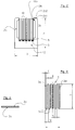
- Fig. 2
- eine Querschnittsansicht auf die Kühlvorrichtung einer anderen erfindungsgemäßen Version;
- Fig. 3
- eine Querschnittsansicht auf die zu einer eiiistückigen Baueinheit vereinten einzelnen Kühlelemente in Form eines mäanderförmigen in Falten gelegten Bandes;
- Fig. 4
- einen Teilquerschnitt des zur Herstellung der Kühlelemente dienenden Bandes;
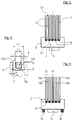
- Fig. 5-7
- alternative Querschnittansichten der Kühlvorrichtung und
- Fig. 8
- einen vergrößerten Teilausschnitt aus dem Verankerungsbereich des Bandes bzw. Profils in einer Grundplattennut im Querschnitt.
- Fig. 1
- a schematic representation of a cooling device according to the invention;
- Fig. 2
- a cross-sectional view of the cooling device of another version according to the invention;
- Fig. 3
- a cross-sectional view of the individual cooling elements combined in an egg-shaped unit in the form of a meandering band folded;
- Fig. 4
- a partial cross section of the band used to produce the cooling elements;
- Fig. 5-7
- alternative cross-sectional views of the cooling device and
- Fig. 8
- an enlarged partial section of the anchoring area of the band or profile in a base plate groove in cross section.
Gemäß Figur 1 ist eine Reihe von elektronischen Bauelementen 1a, 1b und 1c an einer Fläche der Grundplatte 2 so befestigt, daß sich in den elektronischen Bauelementen 1a, 1b und 1c entwickelnde Wärme gut auf die Grundplatte 2 abgeleitet wird. Die Grundplatte 2 besteht z.B. aus Aluminium und bildet ein Profilteil mit den zwei Seitenplatten 2b, welche das zu der Baueinheit 3 mäanderförmig gebogene Band aus lotplattiertem oder handelsüblichem Aluminiumblech seitlich abstützen. In schwalbenschwanzförmige Längsnuten 6 (gemäß Numerierung nach Fig. 8) der Grundplatte 2 ist die aus dem Band gebildete Baueinheit 3 mit den bei diesem Beispiel etwa halbkreisförmig gebogene Mäanderenden 3c (gem. Fig. 3) eingesetzt und verlötet. Als Lot empfiehlt sich ein solches, das sich herstellungstechnisch schnell und mechanisch fest verlöten läßt und darüber hinaus einen nur geringen Wärmeübergangswiderstand zwischen der Grundplatte 2 und der Baueinheit 3 bildet.According to Figure 1, a number of
Die in den Figuren 2 und 3 dargestellten Abmessungen bei dem Ausführungsbeispiel der Erfindung sind folgende:
- a
- = 60 mm
- b
- = 47 mm
- e
- = 48 mm
- f
- = 1 mm
- g
- = 2 mm
- h
- = 4 mm
- i
- = ca.30 mm.
- a
- = 60 mm
- b
- = 47 mm
- e
- = 48 mm
- f
- = 1 mm
- G
- = 2 mm
- H
- = 4 mm
- i
- = approx. 30 mm.
Die elektronischen Bauelemente 1a, 1b, 1c können auch an den als Seitenplatten 2b wirkenden Profilschenkeln der Grundplatte 2 angeordnet sein.The
Gemäß Fig. 4 ist die aus Aluminium bestehende Trägerschicht 3a des blechartigen Bandes für die Baueinheit 3 einer Schichtdicke von 0,9 mm mit einer 0,1 mm dicken Lötschicht 3b aus Spezial-Hartlot aus insb. AlSi an einer Seite überzogen.According to FIG. 4, the aluminum carrier layer 3a of the sheet-like band for the
Auch gemäß Fig. 2, 5, 6, 7 und 8 ist die Baueinheit 3 oder sind die U-förmigen Profile 13 mittels geraden langgestreckten Drahtstücken 8 in den Längsnuten 6 verankert, wie dies in Fig. 8 verdeutlicht ist; dabei sind die langgestreckten Drahtstücke 8 zwischen benachbarten Profilschenkeln 13 des mäanderförmigen Bandes bzw. Profils 13 insb. durch bleibende Verformung so eingeklemmt, daß Mäanderenden 3c (im Bereich der "Täler") oder die unteren Teile der Profilschenkel 13a, 13b in der Nähe des Stegteils 13c innerhalb der Längsnuten 6 leicht nach außen unter einem Winkel von z.B. 5° aufgeweitet werden und sich an die Innenflächen der schwalbenschwanzförmigen Längsnuten 6 anlegen.2, 5, 6, 7 and 8, the
Gemäß Fig. 2, 6 und 7 sind die Drahtstücke 8 am Grund der im Querschnitt U-förmigen Profilteile 13, d.h. auf dem Stegteil 13c, zwischen die Profilschenkel 13a und 13b eingeklemmt und in den Längsnuten 6 verankert.2, 6 and 7, the
Die oberen Enden 2b1 der Seitenplatte 2b bzw. Seitenschenkel sind bevorzugt innen vorspringend, um Anlage- und Kontaktflächen 2b2 für das Band oder den anliegenden Schenkel 13b der Profils 13 zu bilden.The upper ends 2b1 of the
Bevorzugte Maße für das Vorzugsbeispiel von Figur 7 sind:
- e
- = 50,8 mm (Profilhöhe)
- f
- = 1 mm (Banddicke)
- g
- = 3,15 mm (Profilabstand)
- h
- = 5,1 mm (Profilbreite)
- i
- = 30 mm (Breite der Baueinheit im Bereich der Kühlelemente)
- k
- = 3,1 mm (Innenweite der Profile zwischen den Profilschenkeln).
- e
- = 50.8 mm (profile height)
- f
- = 1 mm (tape thickness)
- G
- = 3.15 mm (profile distance)
- H
- = 5.1 mm (profile width)
- i
- = 30 mm (width of the unit in the area of the cooling elements)
- k
- = 3.1 mm (inside width of the profiles between the profile legs).
Das Kühlelement gemäß der Baueinheit 3 von Figur 7 wird wie folgt hergestellt:The cooling element according to the
Zuerst wird der Profilteil der Grundplatte 2 mit dem im Querschnitt insb. schwalbenschwanzförmigen (Fig. 8) Längsnuten 6 aus Aluminium stranggepreßt. Danach werden die 4 U-förmigen Profile 13 mit ihrem den Stegteil 13c aufweisenden Boden bzw. Ende in die Längsnuten 6 eingesteckt. Anschließend werden Drahtstücke 8 mit insb. Rechteckquerschnitt in die Zwischenräume zwischen den Profilschenkeln 13a, 13b eingesteckt und zweckmäßigerweise mittels eines gemeinsamen Werkzeugs, z.B. in einer Presse, bis zum Boden, d.h. Stegteil 13, der Profile 13 eingeschoben; dabei müssen sie eine Kraft überwinden oder werden so stark gedrückt und gepreßt, wodurch die benachbarten Teile der Profilschenkel 13a, 13b bleibend verformt werden und sich an die Seitenwände der Längsnuten 6 flächig unter Klemmwirkung anlegen.First, the profile part of the
Die Profile können nicht nur wie oben erwähnt aus Aluminiumblech hergestellt sein; auch Kupferblech oder andere thermisch gut leitfähige Werkstoffe sind gut geeignet. Gleichfalls eignet sich für die Drahtstücke 8 außer Aluminium auch Kupfer; auch Legierungen solcher mit anderen oder anderer Werkstoffe sind anwendbar.The profiles can not only be made of aluminum sheet as mentioned above; copper sheet or other thermally highly conductive materials are also well suited. Likewise, copper is also suitable for the
Claims (11)
dadurch gekennzeichnet,
daß mindestens zwei Kühlelemente zu einer einstückigen bandförmigen Baueinheit (3) zusammengefaßt sind, die im Querschnitt mindestens ein U-förmiges Profil (13) aufweist, deren die beiden Profilschenkel (3d, 13a, 13b) verbindender Stegteil (3c, 13c) in der Längsnut (6) der Grundplatte (2) verankert istCooling device for electrical or electronic components with a base plate (2) for fastening the components to be cooled and with rib-like cooling elements made of thermally highly conductive material, such as aluminum, which are essentially parallel to one another and at a distance therefrom in heat-transferring contact with the base plate ( 2) that ends of the cooling elements engage in slot-like longitudinal grooves (6) of the base plate (2),
characterized,
that at least two cooling elements are combined to form a one-piece band-shaped unit (3) which has at least one U-shaped profile (13) in cross section, the web part (3c, 13c) connecting the two profile legs (3d, 13a, 13b) in the longitudinal groove (6) of the base plate (2) is anchored
dadurch gekennzeichet,
daß mehrere U-förmige Profile zu einer mäander- bzw. serpentinenförmigen Baueinheit (3) zusammengefaßt sind.Cooling device according to claim 1,
characterized by
that several U-shaped profiles are combined to form a meandering or serpentine-shaped unit (3).
dadurch gekennzeichnet,
daß eine Mehrzahl U-förmiger Profile (13) kammsegmentartig parallel und im Abstand nebeneinander mit der Grundplatte (2) verbunden ist.Cooling device according to claim 1,
characterized,
that a plurality of U-shaped profiles (13) are connected in parallel with a comb segment and at a distance from one another to the base plate (2).
dadurch gekennzeichnet,
daß zwischen die Profilschenkel (13a, 13b) im Bereich der Profilstegteile (13c) ein langgestrecktes Drahtstück (8) eingeklemmt ist, das die U-förmigen Profilteile (13) im Bereich der Profilstegteile (13c) in die Längsnuten (6) der Grundplatte (2) eingeklemmt bzw. eingepreßt hält.Cooling device according to one of the preceding claims,
characterized,
that an elongated piece of wire (8) is clamped between the profile legs (13a, 13b) in the region of the profile web parts (13c), which the U-shaped profile parts (13) in the region of the profile web parts (13c) into the longitudinal grooves (6) of the base plate ( 2) Pinched or pressed in.
dadurch gekennzeichnet,
daß die Drahtstücke (8) benachbarte Teile des Profilteils (13) bzw. der Profilteile (13) in Flächenkontakt an Innenwände der Längsnuten (6) andrücken.Cooling device according to claim 4,
characterized,
that the wire pieces (8) press adjacent parts of the profile part (13) or the profile parts (13) into surface contact on the inner walls of the longitudinal grooves (6).
dadurch gekennzeichnet,
daß die Grundplatte (2) mit den Längsnuten (6) stranggepreßt ist.Cooling device according to one of the preceding claims,
characterized,
that the base plate (2) with the longitudinal grooves (6) is extruded.
dadurch gekennzeichnet,
daß die Längsnuten (6) der Grundplatte (2) im Querschnitt schwalbenschwanzförmig ausgebildet sind.Cooling device according to claim 6,
characterized,
that the longitudinal grooves (6) of the base plate (2) are dovetail-shaped in cross section.
dadurch gekennzeichnet,
daß das Profil (13) aus einem Verbundwerkstoff aus mindestens zwei Schichten, nämlich einer thermisch gut leitfähigen Trägerschicht (3a) und einer plattierten Lötschicht (3b), besteht.Cooling device according to one of the preceding claims,
characterized,
that the profile (13) consists of a composite material of at least two layers, namely a thermally highly conductive carrier layer (3a) and a plated solder layer (3b).
dadurch gekennzeichnet,
daß die Trägerschicht (3a) aus einer Aluminiumlegierung und die Lötschicht (3b) aus einem Hartlot besteht.Cooling device according to claim 8,
characterized,
that the carrier layer (3a) consists of an aluminum alloy and the solder layer (3b) consists of a hard solder.
dadurch gekennzeichnet,
daß das Profil (13) längs der Außenseite von Profilschenkeln (13a, 13b) an die Grundplatte (2) gelötet ist.Cooling device according to one of the preceding claims,
characterized,
that the profile (13) is soldered along the outside of profile legs (13a, 13b) to the base plate (2).
dadurch gekennzeichnet,
daß die mäanderförmige Baueinheit (3) und/oder eine Mehrzahl von U-förmigen Profilen (13) mit deren den Stegteil (3c, 13c) bildenden Enden in die Längsnuten (6) eingesetzt und anschließend die langgestreckten Drahtstücke (8) derart bis an den Boden der U-förmigen Profile (13) gepreßt werden, daß sich der Stegteil (3c,13c) und/oder benachbarte Teile der Profilschenkel (3d, 13a, 13b) bleibend unter Anlage an Innenwände der Längsnuten (6) verformen.Method for producing a cooling device according to one of the preceding claims, in which the cooling elements are inserted into the longitudinal grooves (6) of the base plate (2) and are non-positively connected to the latter,
characterized,
that the meandering structural unit (3) and / or a plurality of U-shaped profiles (13) with their ends forming the web part (3c, 13c) inserted into the longitudinal grooves (6) and then the elongated wire pieces (8) in such a way up to the Bottom of the U-shaped profiles (13) are pressed so that the web part (3c, 13c) and / or adjacent parts of the profile legs (3d, 13a, 13b) permanently deform while resting against the inner walls of the longitudinal grooves (6).
Applications Claiming Priority (3)
| Application Number | Priority Date | Filing Date | Title |
|---|---|---|---|
| DE9412460U | 1994-08-02 | ||
| DE9412460U DE9412460U1 (en) | 1994-08-02 | 1994-08-02 | Cooling device for electrical or electronic components with a base plate and with cooling elements |
| US08/769,547 US5791406A (en) | 1994-08-02 | 1996-12-19 | Cooling device for electrical or electronic components having a base plate and cooling elements and method for manufacturing the same |
Publications (3)
| Publication Number | Publication Date |
|---|---|
| EP0696160A2 true EP0696160A2 (en) | 1996-02-07 |
| EP0696160A3 EP0696160A3 (en) | 1996-03-13 |
| EP0696160B1 EP0696160B1 (en) | 1997-08-20 |
Family
ID=25962307
Family Applications (1)
| Application Number | Title | Priority Date | Filing Date |
|---|---|---|---|
| EP95111250A Expired - Lifetime EP0696160B1 (en) | 1994-08-02 | 1995-07-18 | Cooling device for electrical or electronic components and method for making the same |
Country Status (3)
| Country | Link |
|---|---|
| EP (1) | EP0696160B1 (en) |
| AT (1) | ATE157212T1 (en) |
| DE (2) | DE9412460U1 (en) |
Cited By (4)
| Publication number | Priority date | Publication date | Assignee | Title |
|---|---|---|---|---|
| EP0902469A2 (en) * | 1997-08-28 | 1999-03-17 | Hoogovens Aluminium Profiltechnik Bonn GmbH | Cooling device for electrical or electronic devices |
| DE10065470A1 (en) * | 2000-12-28 | 2002-07-11 | Corus Aluminium Profiltechnik | Heat sink for electrical or electronic components has casting skin removed from edge of cooling ribs formed integrally with base part |
| DE10056387B4 (en) * | 2000-11-14 | 2008-11-13 | Corus Aluminium Profiltechnik Gmbh | Cooling device and method for its production and apparatus for carrying out the method |
| EP2770253A1 (en) * | 2013-02-26 | 2014-08-27 | Showa Denko K.K. | Heat radiation apparatus for LED lighting |
Families Citing this family (3)
| Publication number | Priority date | Publication date | Assignee | Title |
|---|---|---|---|---|
| ATE330329T1 (en) * | 1996-01-31 | 2006-07-15 | Alcan Tech & Man Ag | HEAT SINK FOR SEMICONDUCTOR COMPONENTS OR. DGL. |
| DE19700432A1 (en) * | 1997-01-10 | 1998-07-16 | Swg Metallverarbeitung Und Mon | Heat sink for electric and-or electronic component |
| DE19845374C2 (en) * | 1998-10-02 | 2003-01-02 | Swg Metallverarbeitung Und Mon | Process for the production of heat sinks for electrical and / or electronic components |
Citations (9)
| Publication number | Priority date | Publication date | Assignee | Title |
|---|---|---|---|---|
| US1830375A (en) | 1930-04-04 | 1931-11-03 | Shoop Gertrude | Heat exchange article |
| DE2502472A1 (en) | 1975-01-22 | 1976-07-29 | Siemens Ag | Thyristor heat sink with lateral ribs - has each rib pressed in base-plate groove and with deformations in press region |
| EP0123795A2 (en) | 1983-04-29 | 1984-11-07 | International Business Machines Corporation | Unitary heat sink for an electronic device module |
| DE3518310A1 (en) | 1985-05-22 | 1986-11-27 | Aluminium-Walzwerke Singen Gmbh, 7700 Singen | REFRIGERATOR BODY FOR SEMICONDUCTOR COMPONENTS AND METHOD FOR THE PRODUCTION THEREOF |
| WO1987002443A1 (en) | 1985-10-11 | 1987-04-23 | Neste Oy | Heat transfer member and procedure for manufacturing same |
| DE4106437A1 (en) | 1990-02-28 | 1991-08-29 | Hitachi Ltd | DEVICE FOR COOLING LSI CIRCUITS AND DEVICE FOR COOLING A COMPUTER |
| EP0483058A1 (en) | 1990-10-24 | 1992-04-29 | Alusuisse-Lonza Services Ag | Heat sink for semiconductor components |
| DE9214061U1 (en) | 1992-10-17 | 1992-12-24 | Ets Claude Kremer S.A.R.L., Vianden, Li | |
| DE9302754U1 (en) | 1993-02-25 | 1993-04-15 | Hwang Piin Co. Ltd., Lu Jou Hsiang, Taipeh, Tw |
Family Cites Families (7)
| Publication number | Priority date | Publication date | Assignee | Title |
|---|---|---|---|---|
| GB885150A (en) * | 1959-03-24 | 1961-12-20 | Gallay Ltd | Improvements in or relating to heat exchangers |
| DE3703873A1 (en) * | 1987-02-07 | 1988-08-18 | Sueddeutsche Kuehler Behr | HEAT SINK, ESPECIALLY FOR COOLING ELECTRONIC COMPONENTS |
| JP3122173B2 (en) * | 1990-11-09 | 2001-01-09 | 株式会社東芝 | Heatsink, heatsink, and method of manufacturing heatsink |
| DE4134929A1 (en) * | 1991-10-23 | 1993-04-29 | Vaw Ver Aluminium Werke Ag | Heat transfer body for cooling of semiconductor component - has ribs upstanding from base to grip prongs of component which are forced into corresp. grooves |
| DE9215145U1 (en) * | 1992-08-14 | 1993-01-21 | Hoogovens Aluminium Profiltechnik Gmbh, 7981 Vogt, De | |
| JPH06244328A (en) * | 1993-02-19 | 1994-09-02 | Fujitsu Ltd | Heat sink |
| DE9409517U1 (en) * | 1994-06-13 | 1994-07-28 | Siemens Ag | Heatsink |
-
1994
- 1994-08-02 DE DE9412460U patent/DE9412460U1/en not_active Expired - Lifetime
-
1995
- 1995-07-18 DE DE59500529T patent/DE59500529D1/en not_active Expired - Lifetime
- 1995-07-18 EP EP95111250A patent/EP0696160B1/en not_active Expired - Lifetime
- 1995-07-18 AT AT95111250T patent/ATE157212T1/en active
Patent Citations (9)
| Publication number | Priority date | Publication date | Assignee | Title |
|---|---|---|---|---|
| US1830375A (en) | 1930-04-04 | 1931-11-03 | Shoop Gertrude | Heat exchange article |
| DE2502472A1 (en) | 1975-01-22 | 1976-07-29 | Siemens Ag | Thyristor heat sink with lateral ribs - has each rib pressed in base-plate groove and with deformations in press region |
| EP0123795A2 (en) | 1983-04-29 | 1984-11-07 | International Business Machines Corporation | Unitary heat sink for an electronic device module |
| DE3518310A1 (en) | 1985-05-22 | 1986-11-27 | Aluminium-Walzwerke Singen Gmbh, 7700 Singen | REFRIGERATOR BODY FOR SEMICONDUCTOR COMPONENTS AND METHOD FOR THE PRODUCTION THEREOF |
| WO1987002443A1 (en) | 1985-10-11 | 1987-04-23 | Neste Oy | Heat transfer member and procedure for manufacturing same |
| DE4106437A1 (en) | 1990-02-28 | 1991-08-29 | Hitachi Ltd | DEVICE FOR COOLING LSI CIRCUITS AND DEVICE FOR COOLING A COMPUTER |
| EP0483058A1 (en) | 1990-10-24 | 1992-04-29 | Alusuisse-Lonza Services Ag | Heat sink for semiconductor components |
| DE9214061U1 (en) | 1992-10-17 | 1992-12-24 | Ets Claude Kremer S.A.R.L., Vianden, Li | |
| DE9302754U1 (en) | 1993-02-25 | 1993-04-15 | Hwang Piin Co. Ltd., Lu Jou Hsiang, Taipeh, Tw |
Cited By (6)
| Publication number | Priority date | Publication date | Assignee | Title |
|---|---|---|---|---|
| EP0902469A2 (en) * | 1997-08-28 | 1999-03-17 | Hoogovens Aluminium Profiltechnik Bonn GmbH | Cooling device for electrical or electronic devices |
| EP0902469A3 (en) * | 1997-08-28 | 1999-07-28 | Hoogovens Aluminium Profiltechnik Bonn GmbH | Cooling device for electrical or electronic devices |
| DE10056387B4 (en) * | 2000-11-14 | 2008-11-13 | Corus Aluminium Profiltechnik Gmbh | Cooling device and method for its production and apparatus for carrying out the method |
| DE10065470A1 (en) * | 2000-12-28 | 2002-07-11 | Corus Aluminium Profiltechnik | Heat sink for electrical or electronic components has casting skin removed from edge of cooling ribs formed integrally with base part |
| DE10065470B4 (en) * | 2000-12-28 | 2011-02-17 | Aleris Aluminum Vogt Gmbh | Method for producing a cooling element for electrical, in particular electronic, components |
| EP2770253A1 (en) * | 2013-02-26 | 2014-08-27 | Showa Denko K.K. | Heat radiation apparatus for LED lighting |
Also Published As
| Publication number | Publication date |
|---|---|
| DE9412460U1 (en) | 1995-12-14 |
| ATE157212T1 (en) | 1997-09-15 |
| EP0696160A3 (en) | 1996-03-13 |
| DE59500529D1 (en) | 1997-09-25 |
| EP0696160B1 (en) | 1997-08-20 |
Similar Documents
| Publication | Publication Date | Title |
|---|---|---|
| DE4427854C2 (en) | Cooling device and assembly method therefor | |
| DE2502472C2 (en) | Heat sink for thyristors | |
| DE2813968C2 (en) | Semiconductor device | |
| EP0278240A2 (en) | Heat sink, particularly for cooling electronic components | |
| DE2639979C3 (en) | Semiconductor module | |
| EP0490210B1 (en) | Heat exchanger | |
| EP0805492A2 (en) | Curved metal ceramic substrate | |
| WO2003053118A2 (en) | Cooling device for a chip and method for production thereof | |
| EP0696160B1 (en) | Cooling device for electrical or electronic components and method for making the same | |
| DE2460631C3 (en) | Heat sink for external cooling of thyristors | |
| EP0106262B1 (en) | Heat exchanger, in particular a radiator | |
| EP0632684B1 (en) | Process for manufacturing metal-ceramic substrate | |
| DE3922485C1 (en) | ||
| DE19715540C2 (en) | Method of manufacturing a domed metal-ceramic substrate | |
| DE10103084B4 (en) | Semiconductor module and method for its production | |
| EP1309037A2 (en) | Device for electrically contacting a conductive part of a long body such as tube or cable | |
| DE2930044A1 (en) | COMPONENT. | |
| DE3625238C2 (en) | ||
| DE1916554B2 (en) | Method for manufacturing semiconductor rectifier arrangements | |
| DE2539856A1 (en) | Hot water domestic panel radiator - has grooved heating panels and convection plates with high induction of heat in convection plates | |
| DE20309856U1 (en) | Heat sink for semiconductor components has holders with divergent inner walls and mounting sections with corresponding convergent outer walls | |
| WO1996034245A1 (en) | Flat tube with multiple cavities for heat exchangers and process for manufacturing the same | |
| DE1800192B2 (en) | Process for the serial production of semiconductor arrangements and use of the process for contacting disk-shaped semiconductor bodies Aren: Telefunken Patentverwertungsgesellschaft mbH, 7900 Ulm | |
| DE2448618C3 (en) | Panel radiators | |
| DE3916788C2 (en) |
Legal Events
| Date | Code | Title | Description |
|---|---|---|---|
| PUAI | Public reference made under article 153(3) epc to a published international application that has entered the european phase |
Free format text: ORIGINAL CODE: 0009012 |
|
| PUAL | Search report despatched |
Free format text: ORIGINAL CODE: 0009013 |
|
| AK | Designated contracting states |
Kind code of ref document: A2 Designated state(s): AT CH DE FR GB IT LI |
|
| AK | Designated contracting states |
Kind code of ref document: A3 Designated state(s): AT CH DE FR GB IT LI |
|
| 17P | Request for examination filed |
Effective date: 19960418 |
|
| 17Q | First examination report despatched |
Effective date: 19960710 |
|
| GRAG | Despatch of communication of intention to grant |
Free format text: ORIGINAL CODE: EPIDOS AGRA |
|
| GRAH | Despatch of communication of intention to grant a patent |
Free format text: ORIGINAL CODE: EPIDOS IGRA |
|
| GRAH | Despatch of communication of intention to grant a patent |
Free format text: ORIGINAL CODE: EPIDOS IGRA |
|
| ITF | It: translation for a ep patent filed |
Owner name: STUDIO FERRARIO |
|
| GRAA | (expected) grant |
Free format text: ORIGINAL CODE: 0009210 |
|
| AK | Designated contracting states |
Kind code of ref document: B1 Designated state(s): AT CH DE FR GB IT LI |
|
| REF | Corresponds to: |
Ref document number: 157212 Country of ref document: AT Date of ref document: 19970915 Kind code of ref document: T |
|
| ET | Fr: translation filed | ||
| REG | Reference to a national code |
Ref country code: CH Ref legal event code: NV Representative=s name: GERHARD H. ULRICH PATENTANWALT Ref country code: CH Ref legal event code: EP |
|
| GBT | Gb: translation of ep patent filed (gb section 77(6)(a)/1977) |
Effective date: 19970820 |
|
| REF | Corresponds to: |
Ref document number: 59500529 Country of ref document: DE Date of ref document: 19970925 |
|
| PLBE | No opposition filed within time limit |
Free format text: ORIGINAL CODE: 0009261 |
|
| STAA | Information on the status of an ep patent application or granted ep patent |
Free format text: STATUS: NO OPPOSITION FILED WITHIN TIME LIMIT |
|
| 26N | No opposition filed | ||
| REG | Reference to a national code |
Ref country code: GB Ref legal event code: IF02 |
|
| REG | Reference to a national code |
Ref country code: CH Ref legal event code: NV Representative=s name: AMMANN PATENTANWAELTE AG BERN, CH |
|
| PGFP | Annual fee paid to national office [announced via postgrant information from national office to epo] |
Ref country code: DE Payment date: 20140610 Year of fee payment: 20 Ref country code: CH Payment date: 20140722 Year of fee payment: 20 |
|
| PGFP | Annual fee paid to national office [announced via postgrant information from national office to epo] |
Ref country code: AT Payment date: 20140620 Year of fee payment: 20 Ref country code: FR Payment date: 20140724 Year of fee payment: 20 Ref country code: GB Payment date: 20140721 Year of fee payment: 20 |
|
| PGFP | Annual fee paid to national office [announced via postgrant information from national office to epo] |
Ref country code: IT Payment date: 20140724 Year of fee payment: 20 |
|
| REG | Reference to a national code |
Ref country code: DE Ref legal event code: R071 Ref document number: 59500529 Country of ref document: DE |
|
| REG | Reference to a national code |
Ref country code: CH Ref legal event code: PL |
|
| REG | Reference to a national code |
Ref country code: GB Ref legal event code: PE20 Expiry date: 20150717 |
|
| REG | Reference to a national code |
Ref country code: AT Ref legal event code: MK07 Ref document number: 157212 Country of ref document: AT Kind code of ref document: T Effective date: 20150718 |
|
| PG25 | Lapsed in a contracting state [announced via postgrant information from national office to epo] |
Ref country code: GB Free format text: LAPSE BECAUSE OF EXPIRATION OF PROTECTION Effective date: 20150717 |