EP0689010A2 - Dichtungsanordnung in einer Rauchgasarmatur - Google Patents
Dichtungsanordnung in einer Rauchgasarmatur Download PDFInfo
- Publication number
- EP0689010A2 EP0689010A2 EP95250137A EP95250137A EP0689010A2 EP 0689010 A2 EP0689010 A2 EP 0689010A2 EP 95250137 A EP95250137 A EP 95250137A EP 95250137 A EP95250137 A EP 95250137A EP 0689010 A2 EP0689010 A2 EP 0689010A2
- Authority
- EP
- European Patent Office
- Prior art keywords
- spring steel
- steel sheet
- sheet strip
- sealing seat
- sealing
- Prior art date
- Legal status (The legal status is an assumption and is not a legal conclusion. Google has not performed a legal analysis and makes no representation as to the accuracy of the status listed.)
- Granted
Links
Images


Classifications
-
- F—MECHANICAL ENGINEERING; LIGHTING; HEATING; WEAPONS; BLASTING
- F16—ENGINEERING ELEMENTS AND UNITS; GENERAL MEASURES FOR PRODUCING AND MAINTAINING EFFECTIVE FUNCTIONING OF MACHINES OR INSTALLATIONS; THERMAL INSULATION IN GENERAL
- F16J—PISTONS; CYLINDERS; SEALINGS
- F16J15/00—Sealings
- F16J15/02—Sealings between relatively-stationary surfaces
- F16J15/06—Sealings between relatively-stationary surfaces with solid packing compressed between sealing surfaces
- F16J15/08—Sealings between relatively-stationary surfaces with solid packing compressed between sealing surfaces with exclusively metal packing
- F16J15/0887—Sealings between relatively-stationary surfaces with solid packing compressed between sealing surfaces with exclusively metal packing the sealing effect being obtained by elastic deformation of the packing
- F16J15/0893—Sealings between relatively-stationary surfaces with solid packing compressed between sealing surfaces with exclusively metal packing the sealing effect being obtained by elastic deformation of the packing the packing having a hollow profile
-
- F—MECHANICAL ENGINEERING; LIGHTING; HEATING; WEAPONS; BLASTING
- F16—ENGINEERING ELEMENTS AND UNITS; GENERAL MEASURES FOR PRODUCING AND MAINTAINING EFFECTIVE FUNCTIONING OF MACHINES OR INSTALLATIONS; THERMAL INSULATION IN GENERAL
- F16K—VALVES; TAPS; COCKS; ACTUATING-FLOATS; DEVICES FOR VENTING OR AERATING
- F16K1/00—Lift valves or globe valves, i.e. cut-off apparatus with closure members having at least a component of their opening and closing motion perpendicular to the closing faces
- F16K1/16—Lift valves or globe valves, i.e. cut-off apparatus with closure members having at least a component of their opening and closing motion perpendicular to the closing faces with pivoted closure-members
- F16K1/18—Lift valves or globe valves, i.e. cut-off apparatus with closure members having at least a component of their opening and closing motion perpendicular to the closing faces with pivoted closure-members with pivoted discs or flaps
- F16K1/22—Lift valves or globe valves, i.e. cut-off apparatus with closure members having at least a component of their opening and closing motion perpendicular to the closing faces with pivoted closure-members with pivoted discs or flaps with axis of rotation crossing the valve member, e.g. butterfly valves
- F16K1/226—Shaping or arrangements of the sealing
- F16K1/2263—Shaping or arrangements of the sealing the sealing being arranged on the valve seat
- F16K1/2266—Shaping or arrangements of the sealing the sealing being arranged on the valve seat and being forced into sealing contact with the valve member by a spring or a spring-like member
-
- F—MECHANICAL ENGINEERING; LIGHTING; HEATING; WEAPONS; BLASTING
- F23—COMBUSTION APPARATUS; COMBUSTION PROCESSES
- F23L—SUPPLYING AIR OR NON-COMBUSTIBLE LIQUIDS OR GASES TO COMBUSTION APPARATUS IN GENERAL ; VALVES OR DAMPERS SPECIALLY ADAPTED FOR CONTROLLING AIR SUPPLY OR DRAUGHT IN COMBUSTION APPARATUS; INDUCING DRAUGHT IN COMBUSTION APPARATUS; TOPS FOR CHIMNEYS OR VENTILATING SHAFTS; TERMINALS FOR FLUES
- F23L13/00—Construction of valves or dampers for controlling air supply or draught
- F23L13/02—Construction of valves or dampers for controlling air supply or draught pivoted about a single axis but having not other movement
Definitions
- the invention relates to a seal arrangement in a flue gas fitting according to the preamble of claim 1.
- a generic sealing arrangement is known from DE 38 15 404 A1. It has a circumferential wing sealing seat arranged on the respective flap wing and a corresponding, fixed counter-sealing seat on the housing of the flue gas fitting which cooperates with it. In the locked position, both sealing seats lie directly on top of each other. Since the flue gas fittings are used for flue gas ducts with very large cross-sectional areas (eg 50 to 100 m2), dust deposits and tension can result in the surfaces of the sealing seats not lying flat on one another if the sealing surfaces of the sealing seats are completely rigid.
- the sealing arrangement known from DE 38 15 404 A1 on one of the two sealing seats has a spring steel sheet strip which is convexly curved against the other sealing seat and on which the other sealing seat, i.e. in As a rule, the wing sealing seat is in the locked position of the flap wing.
- the convex curved spring steel sheet strip can adapt exactly to the wing sealing seat under pressure and thus reliably seals.
- the spring-steel strip of the known sealing arrangement is provided with two longitudinally extending creases 90 o and is bent in the assembled state in cross section to form a closed hollow profile.
- Both long sides of the spring steel sheet strip are firmly clamped (for example by means of a screwed-on terminal strip).
- This type of fastening means that the hollow profile of the spring steel sheet strip has considerable spring stiffness and the deformations caused by the adjacent flap wing cause very high bending stresses.
- the object of the invention is to improve a generic flue gas fitting so that the risk of breakage of the spring steel sheet strip of the sealing arrangement is substantially reduced.
- the invention is based on the knowledge that the bending stress of the spring steel sheet strip can be substantially reduced despite maintaining its convex curvature against the corresponding sealing seat if only one of its two long sides is firmly clamped, while the other long side can slide under the pressure of the flap wing on the mounting base of the spring steel sheet strip, so that the convex curvature can easily adapt to the shape of the sealing surface interacting with it.
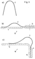
- the spring steel sheet strip 6 in Fig. 1a has a substantially flat shape and only has a longitudinal bend 7 on its left longitudinal side, the function of which is shown in Fig. 1b.
- the profile attached to the fitting housing (also not shown) and forming the counter-seat 10 must have an approximately L-shaped cross-sectional shape, i.e. in addition to the flat bearing surface 1a have, for example, a right-angled free leg 1b.
- the right longitudinal side of the spring steel sheet strip 6 is firmly clamped onto the vertically directed free leg 1b by means of a screwed-on terminal strip 12.
- the spring steel sheet strip 6 has been bent to the left during assembly under elastic deformation until it is on its left longitudinal side lies flat on the horizontal support surface 1a of the sealing seat 10. It bulges convexly over the bearing surface 1 a and is held in this position by a hold-down device 11.
- the hold-down device 11 does not clamp the spring steel sheet strip 6, but only holds it in the manner of a sliding guide. So that the spring steel sheet strip 6 cannot slide out of the slide guide to the right under the hold-down device 11, it has a safety device, which in this case is designed as a longitudinal bend 7. It would of course also be possible to provide a different form of stop (eg thickening).
- FIG. 2 differs from that of FIG. 1 only in that the spring steel sheet strip 5 is supported by an additional narrower spring steel sheet strip 5a, which is flush with the spring steel sheet strip 5 on one long side.
- the spring stiffness in the vicinity of the clamping point is increased compared to the unsupported part of the spring steel sheet strip 5. This leads to a comparatively steeper convex bulge.
- the spring steel sheet strips all have a permanent pre-deformation in the unmounted state, namely a pre-deformation transverse to the longitudinal direction, which is designed as a bulge or buckling. It runs essentially in the central area over the entire length of the spring steel sheet strip.
- this bulge of the spring steel strip 2 is approximately U-shaped. Because of this pre-deformation, the spring steel sheet strip 2 can still assume a convex shape even when it rests on a sealing seat 10 which only has a flat bearing surface 1, on which the right longitudinal side is clamped is (Fig. 3b). However, it is also possible to attach this spring steel sheet strip 2 to an L-shaped sealing seat 10 in a manner similar to that in FIG. 1b (FIG. 3c).
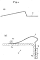
- Fig. 4 shows a further variant, in which the spring steel sheet strip 3 is provided with two opposite longitudinal bends. As can be seen in FIG. 4b, this leads to a higher curvature over the bearing surface 1a.
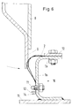
- FIG. 6 shows a section of a flue gas fitting with the sealing arrangement according to the invention.
- the L-shaped sealing seat 10 is part of a U-profile, which is welded to the housing 15 of the flue gas fitting.
- the hold-down device 11 which is also screwed on, on the bearing surface 1a.
- the spring steel sheet strip 2 In the open position of the flap wing 8, the spring steel sheet strip 2 has the thickly extended shape. Its left longitudinal edge lies at the point marked by the dashed line 13.
- the sealing arrangement designed according to the invention drastically reduces the risk of breakage for the spring steel sheet strip, the costs for the sealing arrangement even being reduced.
Landscapes
- Engineering & Computer Science (AREA)
- General Engineering & Computer Science (AREA)
- Mechanical Engineering (AREA)
- Combustion & Propulsion (AREA)
- Chemical & Material Sciences (AREA)
- Gasket Seals (AREA)
- Lift Valve (AREA)
- Prevention Of Fouling (AREA)
- Exhaust Silencers (AREA)
- Safety Valves (AREA)
- Treating Waste Gases (AREA)
- Feeding And Controlling Fuel (AREA)
- Turbine Rotor Nozzle Sealing (AREA)
Abstract
Description
- Die Erfindung betrifft eine Dichtunganordnung in einer Rauchgasarmatur gemäß dem Gattungsbegriff des Patentanspruchs 1.
- Eine gattungsgemäße Dichtungsanordnung ist aus der DE 38 15 404 A1 bekannt. Sie weist einen an dem jeweiligen Klappenflügel angeordneten umlaufenden Flügeldichtsitz und einen entsprechenden, mit diesem zusammenwirkenden feststehenden Gegendichtsitz am Gehäuse der Rauchgasarmatur auf. In der Sperrstellung liegen beide Dichtsitze unmittelbar aufeinander. Da die Rauchgasarmaturen für Rauchgaskanäle mit sehr großen Querschnittsflächen (z.B. 50 bis 100 m²) eingesetzt werden, kann es durch Staubablagerungen und Verspannungen vorkommen, daß die Flächen der Dichtsitze nicht plan aufeinanderliegen, wenn die Dichtflächen der Dichtsitze völlig starr ausgebildet sind. Um die auf diese Weise entstehenden Undichtigkeiten zu vermeiden, weist die aus der DE 38 15 404 A1 bekannte Dichtungsanordnung an einem der beiden Dichtsitze, im Regelfall an dem Gegendichtsitz des Gehäuses der Rauchgasarmatur, einen konvex gegen den anderen Dichtsitz gewölbten Federstahlblechstreifen auf, an dem der andere Dichtsitz, also im Regelfall der Flügeldichtsitz, in der Sperrstellung des Klappenflügels anliegt. Der konvex gewölbte Federstahlblechstreifen kann sich unter Druckwirkung des Flügeldichtsitzes diesem genau anpassen und dichtet somit zuverlässig ab. Der Federstahlblechstreifen der bekannten Dichtungsanordnung ist mit zwei in Längsrichtung verlaufenden Knicken von 90 o versehen und ist im Montagezustand im Querschnitt zu einem geschlossenen Hohlprofil gebogen. Beide Längsseiten des Federstahlblechstreifens sind (beispielsweise mittels angeschraubter Klemmleiste) fest eingespannt. Diese Art der Befestigung führt dazu, daß das Hohlprofil des Federstahlblechstreifens eine beträchtliche Federsteifigkeit aufweist und die von dem anliegenden Klappenflügel bewirkten Verformungen sehr hohe Biegespannungen hervorrufen.
- Insbesondere bei Rauchgasarmaturen, bei denen die Dichtsitze starken Druckwechselbeanspruchungen unterliegen (z.B. Jalousieklappen) kann es unter ungünstigen Umständen zu einem Bruch des Federstahlblechstreifens und somit zur Undichtigkeit der Armatur kommen, so daß eine Reparatur erforderlich wird.
- Aufgabe der Erfindung ist es, eine gattungsgemäße Rauchgasarmatur so zu verbessern, daß die Gefahr eines Bruchs des Federstahlblechstreifens der Dichtungsanordnung wesentlich vermindert wird.
- Gelöst wird diese Aufgabe erfindungsgemäß mit den kennzeichnenden Merkmalen des Anspruchs 1. Vorteilhafte Weiterbildungen der Erfindung sind in den Unteransprüchen 2 bis 6 angegeben.
- Der Erfindung liegt die Erkenntnis zugrunde, daß die Biegebeanspruchung des Federstahlblechstreifens trotz Beibehaltung seiner konvexen Wölbung gegen den korrespondierenden Dichtsitz wesentlich vermindert werden kann, wenn nur eine seiner beiden Längsseiten fest eingespannt wird, während die andere Längsseite unter der Druckeinwirkung des Klappenflügels auf der Befestigungsunterlage des Federstahlblechstreifens gleitend ausweichen kann, so daß sich die konvexe Wölbung leicht der Form der mit ihr zusammenwirkenden Dichtfläche anpassen kann.
- Anhand der in den Fig. 1 bis 6 dargestellten Ausführungsbeispiele wird die Erfindung nachfolgend näher beschrieben. Es zeigen:
- Fig. 1 bis 5
- schematische Darstellungen von Dichtsitzen mit unterschiedlich geformten Federstahlblechstreifen und
- Fig. 6
- einen Ausschnitt aus einer Rauchgasarmatur mit einer erfindungsgemäßen Dichtungsanordnung.
- In den Fig. 1 bis 5 ist jeweils in einer Teildarstellung a) ein Querschnitt durch einen nichtmontierten Federstahlblechstreifen wiedergegeben, während die Teildarstellung b) und ggf. c) den zugehörigen Querschnitt im montierten Zustand zeigt. Der Federstahlblechstreifen 6 in Fig. 1a hat eine im wesentlichen plane Form und weist lediglich an seiner linken Längsseite einen Längsknick 7 auf, dessen Funktion aus Fig. 1b hervorgeht. Um die gewünschte konvex (gegen den nicht dargestellten Flügeldichtsitz) gebogene Form des Federstahlblechstreifens 6 zu erzielen, muß das am (ebenfalls nicht dargestellten) Armaturengehäuse befestigte, den Gegendichtsitz 10 bildende Profil eine etwa L-förmige Querschnittsform haben, also zusätzlich zu der flachen Auflagerfläche 1a einen z.B. rechtwicklig abgewinkelten freien Schenkel 1b aufweisen. Die rechte Längsseite des Federstahlblechstreifens 6 ist mittels einer angeschraubten Klemmleiste 12 fest auf den vertikal gerichteten freien Schenkel 1b gespannt. Der Federstahlblechstreifen 6 ist bei der Montage unter elastischer Verformung nach links gebogen worden, bis er an seiner linken Längsseite auf der horizontalen Auflagerflache 1a des Dichtsitzes 10 flach aufliegt. Er wölbt sich konvex über der Auflagerfläche 1a und wird in dieser Position durch einen Niederhalter 11 gehalten. Der Niederhalter 11 klemmt den Federstahlblechstreifen 6 nicht fest, sondern hält ihn lediglich im Sinne einer Gleitführung. Damit der Federstahlblechstreifen 6 nicht unter dem Niederhalter 11 aus der Gleitführung nach rechts herausrutschen kann, weist er eine Sicherung auf, die in diesem Fall als Längsknick 7 ausgeführt ist. Es wäre selbstverständlich auch möglich, eine andere Form eines Anschlags vorzusehen (z.B. Verdickung).
- Die in Fig. 2 dargestellte Ausführungsform unterscheidet sich von derjenigen der Fig. 1 lediglich dadurch, daß der Federstahlblechstreifen 5 durch einen zusätzlichen schmaleren Federstahlblechstreifen 5a, der an einer Längsseite bündig mit dem Federstahlblechstreifen 5 zusammengelegt ist, gestützt wird. Hierdurch wird die Federsteifigkeit im Nahbereich der Einspannstelle gegenüber dem ungestützten Teil des Federstahlblechstreifens 5 erhöht. Dies führt zu einer vergleichsweise steileren konvexen Auswölbung.
- Die Ausführungen der Fig. 3 bis 5 unterscheiden sich von der Ausführung in Fig. 1 im wesentlichen dadurch, daß die Federstahlblechstreifen alle eine bleibende Vorverformung im unmontirten Zustand aufweisen, und zwar eine Vorverformung quer zur Längsrichtung, die als Auswölbung oder Ausknickung ausgebildet ist. Sie verläuft im wesentlichen im mittleren Bereich über die gesamte Länge des Federstahlblechstreifens.
- In Fig. 3a ist diese Auswölbung des Federstahlhlechstreifens 2 etwa U-förmig ausgebildet. Aufgrund dieser Vorverformung kann der Federstahlblechstreifen 2 selbst dann noch eine konvexe Form annehmen, wenn er auf einem Dichtsitz 10 aufliegt, der lediglich eine ebene Auflagerfläche 1 aufweist, auf dem die rechte Längsseite festgeklemmt ist (Fig. 3b). Es ist aber auch möglich, diesen Federstahlblechstreifen 2 ähnlich wie in Fig. 1b an einem L-förmigen Dichtsitz 10 anzubringen (Fig. 3c).
- Fig. 4 zeigt eine weitere Variante, bei der der Federstahlblechstreifen 3 mit zwei gegensinnigen Längsknicken versehen ist. Dies führt, wie Fig. 4 b erkennen läßt, zu einer höheren Wölbung über der Auflagerfläche 1a.
- Bei der Ausführung gemäß Fig. 5 wurde lediglich die linke Hälfte des Federstahlblechstreifens 4 gewölbt. Im nur einseitig eingespannten Zustand (gestrichelte Darstellung in Fig. 5b) zeigt die freie Längsseite des Federstahlblechstreifens nach rechts und nimmt im fertigmontierten Zustand die ausgezogen dargestellte Form an.
- In Fig. 6 schließlich ist ein Ausschnitt aus einer Rauchgasarmatur mit der erfindungsgemäßen Dichtungsanordnung dargestellt. Der L-förmige Dichtsitz 10 ist Teil eines U-Profils, das an dem Gehäuse 15 der Rauchgasarmatur angeschweißt ist. Der Federstahlblechstreifen 2, der über die angeschraubte Klemmleiste 12 auf dem freien Schenkel 1b fest eingespannt ist, wird an seiner linken Längsseite gleitbar von dem ebenfalls angeschraubten Niederhalter 11 auf der Auflagerfläche 1a gehalten. In geöffneter Stellung des Klappenflügels 8 weist der Federstahlblechstreifen 2 die dick ausgezogene Form auf. Sein linker Längsrand liegt an der durch die gestrichelte Linie 13 markierten Stelle. In der Schließstellung des Klappenflügels 8 liegt deren Dichtsitz 9 fest auf dem Federstahlblechstreifen 2 auf und verformt letzteren in der strichpunktiert dargestellten Weise. Dabei kann die linke Längsseite des Federstahlblechstreifens 2 gleitend nach links ausweichen und liegt dann in der gestrichelt markierten Stellung 14.
- Durch die erfindungsgemäß gestaltete Dichtungsanordnung wird die Bruchgefahr für den Federstahlblechstreifen drastisch reduziert, wobei die Kosten für die Dichtungsanordnung sogar noch vermindert werden.
Claims (6)
- Dichtungsanordnung in einer Rauchgasarmatur, insbesondere in einer Absperrarmatur in Form einer Jalousieklappe, mit mindestens einem bewegbaren Klappenflügel (8), der mit seinem Flügeldichtsitz (9) an einem entsprechenden feststehenden Gegendichtsitz (10) des Armaturengehäuses (15) dichtend zur Anlage bringbar ist, wobei der Flügeldichtsitz (9) oder der Gegendichtsitz (10) mit einem elastisch verformbaren und nach außen konvex über dem jeweiligen Dichtsitz sich wölbenden Federstahlblechstreifen (2 bis 6), der eine erste und eine zweite Längsseite aufweist, belegt ist und die erste Längsseite des Federstahlblechstreifens (2 bis 6) an dem den jeweiligen Dichtsitz bildenden Teil eingespannt ist,
dadurch gekennzeichnet,
daß die zweite Längsseite des Federstahlblechsstreifens (2-6) gleitbar auf dem Teil befestigt ist, an dem die erste Längsseite des Federstahlblechstreifens (2-6) eingespannt ist. - Dichtungsanordnung nach Anspruch 1,
dadurch gekennzeichnet,
daß die zweite Längsseite des Federstahlblechstreifens (2 bis 6) durch einen Niederhalter (11) auf das den jeweiligen Dichtsitz bildende Teil (Gegendichtsitz 10) gedrückt wird. - Dichtungsanordnung nach einem der Ansprüche 1 bis 2,
dadurch gekennzeichnet,
daß das den Federstahlblechstreifen (2 bis 6) tragende Teil ein Blechprofil ist, das im Querschnitt einen von der Auflagerfläche (1a) des Dichtsitzes (10) abgewickelten freien Schenkel (1b) aufweist, auf dem die feste Einspannung angeordnet ist. - Dichtungsanordnung nach einem der Ansprüche 2 bis 3,
dadurch gekennzeichnet,
daß der Federstahlblechstreifen (2 bis 6) an seiner gleitbar aufliegenden Längsseite eine Sicherung gegen ein Herausrutschen aus der durch den Niederhalter (11) gebildeten Gleitführung aufweist. - Dichtungsanordnung nach Anspruch 4,
dadurch gekennzeichnet,
daß die Sicherung als Längsknick (7) am äußersten Längsrand des Federstahlblechstreifens (4, 5, 6) ausgebildet ist. - Dichtungsanordnung nach einem der Ansprüche 1 bis 5,
dadurch gekennzeichnet,
daß der Federstahlblechstreifen (2 bis 6) im unmontierten Zustand über seine gesamte Länge eine bleibende Vorverformung im Sinne einer quer zur Längsrichtung verlaufenden und im wesentlichen im mittleren Bereich des Federstahlblechstreifens (2 bis 6) angeordneten Auswölbung oder Ausknickung aufweist.
Applications Claiming Priority (2)
| Application Number | Priority Date | Filing Date | Title |
|---|---|---|---|
| DE4423330 | 1994-06-22 | ||
| DE4423330A DE4423330C2 (de) | 1994-06-22 | 1994-06-22 | Absperrarmatur für Rauchgase |
Publications (3)
| Publication Number | Publication Date |
|---|---|
| EP0689010A2 true EP0689010A2 (de) | 1995-12-27 |
| EP0689010A3 EP0689010A3 (de) | 1996-09-18 |
| EP0689010B1 EP0689010B1 (de) | 1999-08-11 |
Family
ID=6522164
Family Applications (1)
| Application Number | Title | Priority Date | Filing Date |
|---|---|---|---|
| EP95250137A Expired - Lifetime EP0689010B1 (de) | 1994-06-22 | 1995-06-08 | Dichtungsanordnung in einer Rauchgasarmatur |
Country Status (5)
| Country | Link |
|---|---|
| EP (1) | EP0689010B1 (de) |
| AT (1) | ATE183305T1 (de) |
| CA (1) | CA2152288A1 (de) |
| DE (2) | DE4423330C2 (de) |
| ES (1) | ES2134407T3 (de) |
Cited By (5)
| Publication number | Priority date | Publication date | Assignee | Title |
|---|---|---|---|---|
| EP0754916A2 (de) * | 1995-06-22 | 1997-01-22 | Sammet Dampers Oy | Klappe zur Verwendung in Rauchgas- oder Luftkanälen |
| WO1997021049A1 (fr) * | 1995-12-06 | 1997-06-12 | Cockerill Mechanical Industries S.A. | Joint d'etancheite pour portes de registres de deviation de fumee de centrales electriques |
| WO1999067554A1 (de) * | 1998-06-19 | 1999-12-29 | Mannesmann Ag | Vorrichtung zur abdichtung |
| EP1873426A2 (de) | 2006-06-30 | 2008-01-02 | General Electric Company | Dichtungsanordnung |
| CN110307353A (zh) * | 2019-06-15 | 2019-10-08 | 宁波连通设备集团有限公司 | 密封结构、密封系统及闸板阀 |
Citations (1)
| Publication number | Priority date | Publication date | Assignee | Title |
|---|---|---|---|---|
| DE3815404A1 (de) | 1988-05-05 | 1989-11-16 | Pks Engineering | Schwenkklappenanordnung fuer heissgas-rohrleitungen |
Family Cites Families (4)
| Publication number | Priority date | Publication date | Assignee | Title |
|---|---|---|---|---|
| GB1598427A (en) * | 1977-03-31 | 1981-09-23 | Foster Wheeler Power Prod | Isolating/pressure relief damper |
| US4241895A (en) * | 1978-04-26 | 1980-12-30 | Fmc Corporation | Annular resilient metal valve seat |
| DE3815402A1 (de) * | 1988-05-05 | 1989-11-16 | Pks Engineering | Vorrichtung zur abdichtung |
| DE4204516C1 (en) * | 1992-02-15 | 1993-09-02 | Langerbein-Scharf Gmbh & Co. Kg, 4700 Hamm, De | Gas-conduit stop valve - has U=section rust-proof-steel distance-strip securing ends of U=shaped sealing strip and enclosing base strip |
-
1994
- 1994-06-22 DE DE4423330A patent/DE4423330C2/de not_active Expired - Fee Related
-
1995
- 1995-06-08 DE DE59506570T patent/DE59506570D1/de not_active Expired - Fee Related
- 1995-06-08 ES ES95250137T patent/ES2134407T3/es not_active Expired - Lifetime
- 1995-06-08 EP EP95250137A patent/EP0689010B1/de not_active Expired - Lifetime
- 1995-06-08 AT AT95250137T patent/ATE183305T1/de not_active IP Right Cessation
- 1995-06-21 CA CA002152288A patent/CA2152288A1/en not_active Abandoned
Patent Citations (1)
| Publication number | Priority date | Publication date | Assignee | Title |
|---|---|---|---|---|
| DE3815404A1 (de) | 1988-05-05 | 1989-11-16 | Pks Engineering | Schwenkklappenanordnung fuer heissgas-rohrleitungen |
Cited By (9)
| Publication number | Priority date | Publication date | Assignee | Title |
|---|---|---|---|---|
| EP0754916A2 (de) * | 1995-06-22 | 1997-01-22 | Sammet Dampers Oy | Klappe zur Verwendung in Rauchgas- oder Luftkanälen |
| EP0754916A3 (de) * | 1995-06-22 | 1998-08-05 | Sammet Dampers Oy | Klappe zur Verwendung in Rauchgas- oder Luftkanälen |
| WO1997021049A1 (fr) * | 1995-12-06 | 1997-06-12 | Cockerill Mechanical Industries S.A. | Joint d'etancheite pour portes de registres de deviation de fumee de centrales electriques |
| BE1009809A3 (fr) * | 1995-12-06 | 1997-08-05 | Cockerill Mech Ind Sa | Joint d'etancheite pour portes de registres de deviation de fumee de centrales electriques. |
| WO1999067554A1 (de) * | 1998-06-19 | 1999-12-29 | Mannesmann Ag | Vorrichtung zur abdichtung |
| EP1873426A2 (de) | 2006-06-30 | 2008-01-02 | General Electric Company | Dichtungsanordnung |
| EP1873426A3 (de) * | 2006-06-30 | 2009-10-21 | General Electric Company | Dichtungsanordnung |
| US7775048B2 (en) | 2006-06-30 | 2010-08-17 | General Electric Company | Seal assembly |
| CN110307353A (zh) * | 2019-06-15 | 2019-10-08 | 宁波连通设备集团有限公司 | 密封结构、密封系统及闸板阀 |
Also Published As
| Publication number | Publication date |
|---|---|
| CA2152288A1 (en) | 1995-12-23 |
| EP0689010A3 (de) | 1996-09-18 |
| ES2134407T3 (es) | 1999-10-01 |
| DE4423330A1 (de) | 1996-01-04 |
| DE4423330C2 (de) | 1996-06-05 |
| EP0689010B1 (de) | 1999-08-11 |
| DE59506570D1 (de) | 1999-09-16 |
| ATE183305T1 (de) | 1999-08-15 |
Similar Documents
| Publication | Publication Date | Title |
|---|---|---|
| DE10044268C2 (de) | Verriegelungselement mit einer Konterplatte für die schraublose Adaption mit einem Klemm- und Verriegelungsdachprofilblech für Flachdächer | |
| DE3342362A1 (de) | Vorrichtung zur fuehrung und halterung einer fensterscheibe in einem kraftfahrzeug | |
| EP2461119A2 (de) | Klemme für ein Plattenelement, insbesondere für ein Photovoltaikmodul | |
| EP0847346B1 (de) | Wischblatt mit windleitfläche für scheibenwischanlagen von kraftfahrzeugen | |
| DE3035170A1 (de) | Dichtung fuer gassperrventile | |
| DE4423330C2 (de) | Absperrarmatur für Rauchgase | |
| EP0827580B1 (de) | Vorrichtung zur abdichtung zwischen beweglichen anlagenteilen | |
| DE10216625B4 (de) | Befestigungsvorrichtung für eine abdichtende Halterung eines Flächenkörpers | |
| EP0830529B1 (de) | Vorrichtung zur abdichtung zwischen beweglichen anlagenteilen | |
| DE19651365C5 (de) | Vorrichtung zur vorläufigen Halterung von Platten und Halterungen an Riegel- und Pfostenfassaden | |
| DE102018102488A1 (de) | Anordnung zur Positionierung eines Flachteils an einem Schaltschrankrahmengestell sowie ein entsprechendes Verfahren | |
| DE19919247B4 (de) | Führungsschiene für ein Linearlager | |
| DE102007047773A1 (de) | Profil | |
| EP0526748B1 (de) | Absperrarmatur | |
| DE3737833C1 (en) | Flat gasket | |
| DE102007020187A1 (de) | Plattenwärmetauscher | |
| DE19828896C1 (de) | Vorrichtung zur Abdichtung | |
| DE4028898A1 (de) | Dichtungshalteteil | |
| DE3324139C2 (de) | Elastisches Befestigungselement | |
| DE602004004292T2 (de) | Abgasleitungshalter, verfahren zur befestigung eines abgasleitungshalters | |
| DE202019103599U1 (de) | Vorrichtung zum Verspannen von Rahmenprofilen an Lüftungskanälen | |
| DE102006040882A1 (de) | Vorhanggassack-Modul | |
| DE102021204717A1 (de) | Bauteil und Wärmeübertrager | |
| DE102022205375A1 (de) | Gleitschiene für einen Türantrieb | |
| DE102022003335A1 (de) | Befestigung und Abdichtung einer Vorsatzscheibe |
Legal Events
| Date | Code | Title | Description |
|---|---|---|---|
| PUAI | Public reference made under article 153(3) epc to a published international application that has entered the european phase |
Free format text: ORIGINAL CODE: 0009012 |
|
| AK | Designated contracting states |
Kind code of ref document: A2 Designated state(s): AT BE DE ES FR GB IT NL |
|
| PUAL | Search report despatched |
Free format text: ORIGINAL CODE: 0009013 |
|
| AK | Designated contracting states |
Kind code of ref document: A3 Designated state(s): AT BE DE ES FR GB IT NL |
|
| 17P | Request for examination filed |
Effective date: 19961129 |
|
| GRAG | Despatch of communication of intention to grant |
Free format text: ORIGINAL CODE: EPIDOS AGRA |
|
| GRAG | Despatch of communication of intention to grant |
Free format text: ORIGINAL CODE: EPIDOS AGRA |
|
| GRAH | Despatch of communication of intention to grant a patent |
Free format text: ORIGINAL CODE: EPIDOS IGRA |
|
| 17Q | First examination report despatched |
Effective date: 19990201 |
|
| GRAH | Despatch of communication of intention to grant a patent |
Free format text: ORIGINAL CODE: EPIDOS IGRA |
|
| GRAA | (expected) grant |
Free format text: ORIGINAL CODE: 0009210 |
|
| AK | Designated contracting states |
Kind code of ref document: B1 Designated state(s): AT BE DE ES FR GB IT NL |
|
| REF | Corresponds to: |
Ref document number: 183305 Country of ref document: AT Date of ref document: 19990815 Kind code of ref document: T |
|
| RTI1 | Title (correction) |
Free format text: SEALING STRUCTURE FOR A FLUE GAS VALVE |
|
| GBT | Gb: translation of ep patent filed (gb section 77(6)(a)/1977) |
Effective date: 19990812 |
|
| REF | Corresponds to: |
Ref document number: 59506570 Country of ref document: DE Date of ref document: 19990916 |
|
| REG | Reference to a national code |
Ref country code: ES Ref legal event code: FG2A Ref document number: 2134407 Country of ref document: ES Kind code of ref document: T3 |
|
| ITF | It: translation for a ep patent filed |
Owner name: GUZZI E RAVIZZA S.R.L. |
|
| ET | Fr: translation filed | ||
| PG25 | Lapsed in a contracting state [announced via postgrant information from national office to epo] |
Ref country code: AT Free format text: LAPSE BECAUSE OF NON-PAYMENT OF DUE FEES Effective date: 20000608 |
|
| PG25 | Lapsed in a contracting state [announced via postgrant information from national office to epo] |
Ref country code: ES Free format text: LAPSE BECAUSE OF NON-PAYMENT OF DUE FEES Effective date: 20000609 |
|
| PLBE | No opposition filed within time limit |
Free format text: ORIGINAL CODE: 0009261 |
|
| STAA | Information on the status of an ep patent application or granted ep patent |
Free format text: STATUS: NO OPPOSITION FILED WITHIN TIME LIMIT |
|
| PG25 | Lapsed in a contracting state [announced via postgrant information from national office to epo] |
Ref country code: BE Free format text: LAPSE BECAUSE OF NON-PAYMENT OF DUE FEES Effective date: 20000630 |
|
| 26N | No opposition filed | ||
| BERE | Be: lapsed |
Owner name: MANNESMANN A.G. Effective date: 20000630 |
|
| PG25 | Lapsed in a contracting state [announced via postgrant information from national office to epo] |
Ref country code: NL Free format text: LAPSE BECAUSE OF NON-PAYMENT OF DUE FEES Effective date: 20010101 |
|
| NLV4 | Nl: lapsed or anulled due to non-payment of the annual fee |
Effective date: 20010101 |
|
| PG25 | Lapsed in a contracting state [announced via postgrant information from national office to epo] |
Ref country code: FR Free format text: LAPSE BECAUSE OF NON-PAYMENT OF DUE FEES Effective date: 20010831 |
|
| REG | Reference to a national code |
Ref country code: FR Ref legal event code: ST |
|
| REG | Reference to a national code |
Ref country code: GB Ref legal event code: IF02 |
|
| REG | Reference to a national code |
Ref country code: ES Ref legal event code: FD2A Effective date: 20010712 |
|
| PGFP | Annual fee paid to national office [announced via postgrant information from national office to epo] |
Ref country code: GB Payment date: 20040524 Year of fee payment: 10 |
|
| PGFP | Annual fee paid to national office [announced via postgrant information from national office to epo] |
Ref country code: DE Payment date: 20040525 Year of fee payment: 10 |
|
| PG25 | Lapsed in a contracting state [announced via postgrant information from national office to epo] |
Ref country code: IT Free format text: LAPSE BECAUSE OF NON-PAYMENT OF DUE FEES;WARNING: LAPSES OF ITALIAN PATENTS WITH EFFECTIVE DATE BEFORE 2007 MAY HAVE OCCURRED AT ANY TIME BEFORE 2007. THE CORRECT EFFECTIVE DATE MAY BE DIFFERENT FROM THE ONE RECORDED. Effective date: 20050608 Ref country code: GB Free format text: LAPSE BECAUSE OF NON-PAYMENT OF DUE FEES Effective date: 20050608 |
|
| PG25 | Lapsed in a contracting state [announced via postgrant information from national office to epo] |
Ref country code: DE Free format text: LAPSE BECAUSE OF NON-PAYMENT OF DUE FEES Effective date: 20060103 |
|
| GBPC | Gb: european patent ceased through non-payment of renewal fee |
Effective date: 20050608 |
|
| PG25 | Lapsed in a contracting state [announced via postgrant information from national office to epo] |
Ref country code: FR Free format text: LAPSE BECAUSE OF NON-PAYMENT OF DUE FEES Effective date: 20000630 |