EP0687166B1 - An ostomy coupling - Google Patents
An ostomy coupling Download PDFInfo
- Publication number
- EP0687166B1 EP0687166B1 EP94908291A EP94908291A EP0687166B1 EP 0687166 B1 EP0687166 B1 EP 0687166B1 EP 94908291 A EP94908291 A EP 94908291A EP 94908291 A EP94908291 A EP 94908291A EP 0687166 B1 EP0687166 B1 EP 0687166B1
- Authority
- EP
- European Patent Office
- Prior art keywords
- coupling part
- coupling
- annular
- locking ring
- beak
- Prior art date
- Legal status (The legal status is an assumption and is not a legal conclusion. Google has not performed a legal analysis and makes no representation as to the accuracy of the status listed.)
- Expired - Lifetime
Links
- 230000008878 coupling Effects 0.000 title claims abstract description 242
- 238000010168 coupling process Methods 0.000 title claims abstract description 242
- 238000005859 coupling reaction Methods 0.000 title claims abstract description 242
- 210000003323 beak Anatomy 0.000 claims abstract description 47
- 239000000853 adhesive Substances 0.000 claims abstract description 24
- 230000001070 adhesive effect Effects 0.000 claims abstract description 24
- 238000007789 sealing Methods 0.000 claims description 17
- 230000000717 retained effect Effects 0.000 claims description 2
- 239000000463 material Substances 0.000 description 14
- 230000000694 effects Effects 0.000 description 10
- 239000011324 bead Substances 0.000 description 7
- 238000004519 manufacturing process Methods 0.000 description 7
- 230000007423 decrease Effects 0.000 description 4
- 210000003811 finger Anatomy 0.000 description 3
- 238000005452 bending Methods 0.000 description 2
- 230000009975 flexible effect Effects 0.000 description 2
- 238000003466 welding Methods 0.000 description 2
- 210000001072 colon Anatomy 0.000 description 1
- 210000005069 ears Anatomy 0.000 description 1
- 210000003608 fece Anatomy 0.000 description 1
- 239000011888 foil Substances 0.000 description 1
- 238000007455 ileostomy Methods 0.000 description 1
- 210000003405 ileum Anatomy 0.000 description 1
- 238000002347 injection Methods 0.000 description 1
- 239000007924 injection Substances 0.000 description 1
- 238000001746 injection moulding Methods 0.000 description 1
- 210000004932 little finger Anatomy 0.000 description 1
- 230000001095 motoneuron effect Effects 0.000 description 1
- 210000000056 organ Anatomy 0.000 description 1
- 230000000149 penetrating effect Effects 0.000 description 1
- 230000028327 secretion Effects 0.000 description 1
- 210000003708 urethra Anatomy 0.000 description 1
- 239000002699 waste material Substances 0.000 description 1
Images

Classifications
-
- A—HUMAN NECESSITIES
- A61—MEDICAL OR VETERINARY SCIENCE; HYGIENE
- A61F—FILTERS IMPLANTABLE INTO BLOOD VESSELS; PROSTHESES; DEVICES PROVIDING PATENCY TO, OR PREVENTING COLLAPSING OF, TUBULAR STRUCTURES OF THE BODY, e.g. STENTS; ORTHOPAEDIC, NURSING OR CONTRACEPTIVE DEVICES; FOMENTATION; TREATMENT OR PROTECTION OF EYES OR EARS; BANDAGES, DRESSINGS OR ABSORBENT PADS; FIRST-AID KITS
- A61F5/00—Orthopaedic methods or devices for non-surgical treatment of bones or joints; Nursing devices ; Anti-rape devices
- A61F5/44—Devices worn by the patient for reception of urine, faeces, catamenial or other discharge; Colostomy devices
- A61F5/445—Colostomy, ileostomy or urethrostomy devices
- A61F5/448—Means for attaching bag to seal ring
-
- A—HUMAN NECESSITIES
- A61—MEDICAL OR VETERINARY SCIENCE; HYGIENE
- A61F—FILTERS IMPLANTABLE INTO BLOOD VESSELS; PROSTHESES; DEVICES PROVIDING PATENCY TO, OR PREVENTING COLLAPSING OF, TUBULAR STRUCTURES OF THE BODY, e.g. STENTS; ORTHOPAEDIC, NURSING OR CONTRACEPTIVE DEVICES; FOMENTATION; TREATMENT OR PROTECTION OF EYES OR EARS; BANDAGES, DRESSINGS OR ABSORBENT PADS; FIRST-AID KITS
- A61F5/00—Orthopaedic methods or devices for non-surgical treatment of bones or joints; Nursing devices ; Anti-rape devices
- A61F5/44—Devices worn by the patient for reception of urine, faeces, catamenial or other discharge; Colostomy devices
- A61F5/445—Colostomy, ileostomy or urethrostomy devices
- A61F2005/4486—Colostomy, ileostomy or urethrostomy devices with operable locking ring
Definitions
- the present invention relates to an ostomy coupling of the kind comprising a first and a second annular coupling part and a locking ring, where one of the coupling parts is secured to a selfadhesive plate or disc by which it is attachable to the ostomy patient around his stoma, and where the other coupling part carries a collection receptacle or closing plug, and where the locking ring is intended for holding together the first and the second coupling part in tight and secure contact with each other.
- an ostomy patient or ostomist means a person who has a colostomy, an ileostomy or an urostomy.
- a projection of the colon, ileum or urethra has been performed surgically, so that the body's waste products passing through these organs are discharged through an artificial opening, and are collected continuously or at intervals in a collection receptacle, such as a foil bag. If the collection is performed at intervals, the collection receptacle may in the intervening periods be replaced by a closing plug, as known e.g. from DK patent specification No. 153 122.
- the collection bag or the closing plug may be attached directly around the stoma by means of an adhesive disc, but since these parts must be changed even several times daily, and since frequent removal of such an adhesive disc from the skin may cause extreme damage thereto, use is generally made of two-part ostomy equipment consisting of an adhesive disc which is attachable around the ostomist's stoma, and on the non-adhesive surface of which an annular coupling part is attached, often called a plate coupling part, which can be coupled to another annular coupling part which carries a collection receptacle or a closing plug.
- axial pressure and pulling forces are meant forces which in the mounting and demounting situation influence the skin area around the stoma with pressure and pull, respectively.
- axial direction are meant directions which are essentially parallel to the centre axis of the coupling parts.
- the axial thickness of a coupling ring or locking ring thus denotes the distance between two planes which are perpendicular to the centre axis and intersect the surface or line on the coupling or locking ring which in a use situation is closest to the user's stoma-surrounding skin surface and remotest from the user's stoma-surrounding skin surface, respectively.
- a coupling of the above kind is known e.g. from EP patent specification No. 347 025.
- the ostomy coupling disclosed therein consists of two annular coupling parts, one of which is attached to an adhesive disc for attachment around a stoma, and the other carries a collection bag, and a locking ring which locks together the two coupling parts.
- the two coupling parts each have a closed loop-form, i.e. that in their annular extension they stretch a distance in axial direction away from the adhesive disc or the collection bag, respectively, and deflect in radial outward direction.
- the part on the first and the second coupling part, respectively, which strecthes radially outwards, has plane surfaces.
- a similar ostomy coupling is known from WO published specifications No. 91/01118 and 91/01119.
- the ostomy coupling therein disclosed differs from the one mentioned above in having a primary and a secondary coupling mechanism, and in the two coupling parts not having plane contact surfaces.
- the two coupling parts each have projecting parts being capable of passing into mutual engagement so as to form a primary tight assembly of the coupling parts.
- This primary coupling together and uncoupling thereof call for moderate axial pressure and pulling forces.
- another locking ring with U-shape is positioned around the coupling part.
- This locking ring which constitutes the secondary coupling mechanism, embraces the radially projecting parts of the two coupling parts without, however, necessarily having squeezing effect thereon.
- the secondary coupling mechanism will thus not be loaded under normal circumstances, but only in case of a substantial pull in the bag part.
- the locking rings described above must, however, necessarily have a certain axial thickness, since the locking rings have two annular radially inwardly projecting legs or protrusions for enclosing the annular radially outwardly projecting parts of the two coupling parts. In view of material strength and manufacturing tolerances there is thus a lower limit for the axial thickness of the coupling.
- GB patent specification No. 2 215 212 discloses an ostomy coupling consisting of two coupling parts and a locking ring, which only has one annular radially inwardly projecting protrusion.
- One of the coupling parts is of a deformable material and is, as described above, attached to an adhesive disc which projects outwardly therefrom in a closed loop-form so as to form a collar having an annular groove.
- the other annular coupling part is attached to a collection bag and extends outwardly therefrom in axial direction, and is furthermore provided with a small annular beak.
- the two coupling parts are assembled by one deformable coupling part being positioned in radial direction over the other, so that the beak in the second coupling part engages with an annular recess in the deformable one coupling part.
- This engagement between the beak and the recess has in itself no significant strength because of the flexible property of the deformable material.
- the locking ring is thereafter positioned in the annular edge, whereafter it is locked and thereby squeezes the deformable coupling part against the other coupling part.
- This last described ostomy coupling may thus be shaped with a smaller axial thickness than ostomy couplings where the locking ring has two annular radially inwardly directed legs or protusions which in the coupling situation are to embrace and hold or squeeze together radially outwardly projecting parts on the two coupling parts.
- an ostomy coupling comprising a first and a second annular coupling part and a locking ring for locking together the two coupling parts, where one of the two coupling parts is attached to an adhesive disc and the other of the two coupling parts carries a collection receptacle or a closing plug, the first coupling part comprising a collar with a radially outwardly projecting annular edge for forming a groove having an in radial direction innermost groove section, and an in its in radial direction inner side positioned annular recess, and the second coupling part comprising an axial projecting part with an annular radially outwardly projecting beak being capable of engaging with the annular recesss in the first coupling part when the said first coupling part is positioned around the second coupling part, and where the locking ring has an annular in radial direction inwardly projecting protrusion, and that the locking ring is positioned in the groove of the first coupling part, the said
- the coupling ring according to the invention is fairly easy to couple on and off, since the two coupling parts during the coupling together are first coupled together by a primary coupling mechanism, the first coupling part being forced over the second coupling part by use of small or moderate axially directed pressure forces, whereby the annular beak of the second coupling part will engage with the recess in the first coupling part, whereafter the locking ring, which may already be loosely positioned in the groove of the first coupling part without close contact with groove bottom and groove walls, is locked, so that the radially inwardly directed protrusions of the locking ring abut tightly against the bottom and walls of the groove at least in an area, without, however, influencing the first coupling part with appreciable squeeze forces.
- the locking ring is lockable by application of moderate or slight finger strength.
- the first coupling part At loads which try to tear the two coupling parts apart, the first coupling part will be fixedly squeezed between the annular beak of the second coupling part and the radially inwardly projecting protrusions of the locking ring, whereby the coupling strength will increase.
- loads to which an ostomy coupling according to the invention is exposed in use contribute to increasing the coupling strength and consequently the tightness and safety against unintended removal of the collecting receptacle or the closing plug.
- the first coupling part is sealed to a collection bag or a closing plug, and the second coupling part is sealed to an adhesive disc.
- the annular groove in the first coupling part is preferably very narrow in the in radial direction innermost part, i.e. less than 1 mm wide, and expands width-wise in radial outward direction, preferably in one or more steps.
- groove width is meant the distance between the wall surfaces of the groove on a line which is parallel to the centre line of the coupling part.
- the radially inwardly projecting protrusion of the locking ring is preferably so shaped as to correspond to the in radial direction innermost and narrowest part of the annular groove of the first coupling part.
- the sealing surface between the two coupling parts is constituted by the contact between the beak on the second coupling part and the recess in the first coupling part.
- These parts are preferably so constructed that there is an annular narrow sealing surface enclosed on both sides by annular clearances between the beak and the first coupling part.
- the sealing surface is positioned at a distance from the tip of the beak, and that the sealing surface is thus constituted by the contact between an annular surface area on the recess of the first coupling part and an annular surface area on one of the surfaces of the beak, and that this one of the surfaces of the beak in an area which adjoins the tip of the beak is not in direct contact with the first coupling part.
- the annular recess in the first coupling part is preferably so shaped as to have an annular surface which is essentially perpendicular to the centre axis and faces the point of attachment of this coupling part to the collection receptacle, the closing plug, or the adhesive disc, and at the same time the beak of the second coupling part is so shaped as to have an annular surface which corresponds to the annular surface of the recess, so that these two surfaces, which are essentially perpendicular to the centre axis, abut against each other when the coupling is locked.
- the locking ring is provided with a two-step lock in the way it is disclosed in WO 91/01118.
- the locking ring it is provided with an in radial direction inner spring which extends throughout the entire annular extension of the ring, the locking ring, as seen in section, being curved in the area which projects radially outwards from the annular protrusion.
- the locking ring comprises, as seen in section, an S-shaped segment or intermediate piece. According to this embodiment it is achieved that the dependency of the coupling efficiency on the manufacturing tolerances of the units becomes significantly reduced. Further, the coupling will seem less rigid, it will maintain a good seal even upon wringing and bending the entire coupling in use, and it will consequently be more pleasant for ostomy patients to wear.
- the locking ring and the plate coupling part are preferably made of an essentially non-deformable polymeric material. For reasons of production it is particularly advantageous to make the coupling parts and the locking ring by injection moulding in a material suited for this purpose.
- the locking ring Before the two coupling parts of the ostomy coupling are coupled together, the locking ring is preferably placed in the groove of the first coupling part in its non-locked position. If the locking ring is provided with a two-step lock as mentioned above, the locking ring may advantageously be positioned in its first locking-position, so that the annular radially inwardly projecting protrusion of the locking ring is not in close contact with the bottom of the groove throughout the entire annular extension of the groove.
- the locking ring is opened, whereafter the two coupling parts are separated from each other by application of small or moderate pulling forces, a pulling flap preferably being positioned in the coupling part which carries a collection receptacle or a closing plug.
- this pulling flap is positioned on the annular collar edge of the coupling part, since by that means it is avoided that the locking ring falls out or is torn out of the groove during removal of the receptacle or plug carrying coupling part.
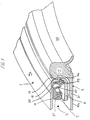
- Figs. 1, 2 and 3 show an especially preferred embodiment of the ostomy coupling according to the invention in mounted and demounted state, respectively.
- the ostomy coupling comprises a first coupling part 1, a second coupling part 2, and a locking ring 3.
- the first coupling part 1 carries in a manner known per see a not shown collection receptacle or closing plug being attached e.g. by welding to an annular surface area 4a throughout the entire annular extension of the coupling part.
- This first coupling part is hereinafter designated the bag coupling part.
- the second coupling part 2 hereinafter designated the plate coupling part, is in a manner known per se attached e.g. by welding to a not shown adhesive disc or plate in an annular surface area 21a, by which it can be adhered to the skin area around a stoma.
- the bag coupling part comprises a base portion 4 having a collar 5 projecting axially from the base portion 4, the said collar having a radially outwardly projecting annular edge 6 for forming a groove 7.
- the width of the groove which is defined as the distance between the inner wall surfaces 8 and 9 of the groove, decreases in step 8b, 9b from both side walls 8, 9 in radially inward direction so as to form an in radial direction innermost annular groove section 7a with groove walls 8a and 9a and a groove bottom 10.
- the groove width decreases in one step 8b, 9b from the side wall 8 closest to the user and the side wall 9 most remote from the user, respectively, in the situation of use.
- the groove width may just as well decrease in several steps from each of the two side walls, but it is particularly advantageous that the side wall decreases from the side wall precisely in one step 9b, which is explained in more detail below.
- the step 9b at least in the area closest to the base portion 5 tapers radially inwardly from the base portion 4.
- the bag coupling part has a recess 11 in its in radial direction inner side of the collar 5.
- the recess is so positioned that in axial direction it is closer to the attachment surface 4a of the coupling part to the collection receptacle or the closing plug.
- the recess 11 has a first essentially plane surface 12 which is essentially perpendicular to the centre axis C-C' of the coupling part, which is indicated in fig. 2, and a second rounded surface 13 with an annular sealing rib 14.
- the surface 12 may be inclined in relation to the centre axis C-C', it, however, has to be ensured that the beak of the plate coupling part which is described later on is capable of engaging with the recess with a certain strength.
- the in radial direction innermost section of the rounded surface 13 further constitutes the wall surface of an annular lip 15 which forms a secondary seal when the coupling parts are coupled together.
- the plate coupling part 2 comprises a base portion 21 with an axially outwardly projecting annular part 17 having an annular inwardly projecting beak 18 with a first beak surface 19 which is essentially perpendicular to the centre axis C-C' or has an angle with corresponds to the angle of the recess surface 12 to the centre axis C-C', and a second preferably rounded beak surface 20 which, however, in the area 20a, 20b which adjoins the annular tip 19a of the beak between the first beak surface 19 and the second beak surface 20 is essentially parallel to the centre axis C-C'.
- the beak 18 of the plate coupling part is so shaped as to be capable of engaging with the recess 11 of the bag coupling part, which is explained later on.
- the base portion 21 of the bag coupling part is in the annular area closest to the axially outwardly projecting part 17, axially thicker than the in radial direction outermost area of the base portion 21 to which the adhesive disc is attached.
- the coupling part On the in radial direction inner side of the projecting part 17 of the plate coupling, the coupling part is provided with an annular flange 22.
- This flange has two functions. When the plate coupling part is attached around a stoma, this flange will prevent faeces or other secretion from the stoma from penetrating between the adhesive plate and the plate coupling part. This is an important hygienic measure, since the plate coupling part is often used for several days, and must consequently be kept clean.
- the flange 22 may furthermore act as attachment rib for a convex ring which some ostomy patients have to use.
- the flange 22 could, however, just as well be replaced by in radial direction inwardly projecting knobs or the like for retaining a convex ring in the way it is known from e.g. the applicant's DK patent application No. 0371/92 corresponding to WO 93/18725.
- the base flange 21a may furthermore in a manner known per se be provided with not shown ears for attachment of a supporting belt.
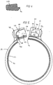
- the locking ring 3 which is intended for positioning in the groove 7 of the bag coupling part, as shown in fig. 1, comprises an annular base ring 25 and an in radial direction inwardly projecting annular protrusion 26 which fits into the in radial direction innermost groove section 7a of the coupling part.
- the base ring and the protrusion are connected by an intermediate piece 27 which is bent so as to have a S-shaped cross-section.
- the resilient effect between the base ring 25 and the protrusion 26 may of course just as well be obtained by an intermediate piece having any other bent cross-section, e.g. having a C-shaped cross-section, or the intermediate piece may be inclined in relation to the radial direction between the base ring 25 and the protrusion 26.
- first and a second guide flange 28, 29 with rounded edges project in oppositely directed axial directions.
- the object of these guide flanges 28, 29 is to guide the locking ring 3 during positioning thereof in groove section 7 and during locking thereof, so that the protrusion 26 is guided into the innermost groove section 7a.
- the first guide flange 28, which extends in axial direction towards the base portion 4 of the first coupling part when the coupling is mounted, further has a fortifying effect on the seals of the coupling, which is explained in more detail below.
- the locking ring may also be shaped without intermediate piece, this locking ring consisting of a base ring 125 from which a protrusion 26 corresponding to the protrusion 26 in the embodiment shown in fig. 1-3 projects in radial inward direction.
- the locking ring may advantageously be provided with a two-step lock like those described in WO91/01118.
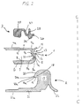
- Fig. 5 shows a locking ring having a preferred two-step lock.
- the locking ring corresponds to the one shown in fig. 1-3, and thus consists of a base ring 25, an intermediate piece 27, and a protrusion 26.
- the locking ring is provided with a cut for forming two ends 40, 41, being provided with a male locking unit 42 and a female locking unit 43, respectively, which may be passed into a primary and a secondary mutual engagement.
- the male locking unit 42 comprises a flat disc 44 which projects radially from the locking ring.
- the flat disc 44 comprises a vane 45 which projects from the lead-in edge 46 which is first introduced into the female locking unit. From the first side of the vane closest to the lead-in edge 46 a first bead 47 projects in axial direction, and from the other side of the vane closest to the vane tip a second bead 48 projects in axial direction.
- the female locking unit comprises a flat housing 49 which also projects radially from the locking ring.
- the housing 49 has a first wall 50 and a second wall 51, each being provided with a window 52, 53.
- the housing has an open ceiling 54 and an open front wall 55.
- the locking ring 3 When opening the secondary lock of the locking ring a slight pressure is exerted on the vane 45 through the window 53, until the bead slips out of the engagement with the window 53.
- the locking ring 3 if preferably elastically deformable at least in a section of its annular extension, so that the bead 48 by itself leaps out of the engagement with the window 53 by a slight pressure on the vane 45.
- the locking ring 3 and the first coupling part 1 may advantageously, and in the way it is shown in the preferred embodiment of the invention in fig. 1, be so constructed that the locking ring prior to mounting the coupling is positioned in the groove 7 in its primary locking position, in the way it is known from the applicant's WO patent application No. 91/01119.
- the maximum inner diameter of the locking ring, when the locking ring is in its primary locking position is smaller than the outer diameter of the collar edge 6 of the first coupling part. This is significantly advantageous handling-wise, since the locking ring 3 already at the moment of sale may be positioned in the groove 7 in its primary locking position, whereby the user avoids trouble of handling a separate locking ring.
- the plate coupling part is attached in a manner known per se around a stoma.
- the bag coupling part is forced over the axially outwardly projecting annular part 17 of the plate coupling part, so that the beak 18 engages with the recess 11.
- the locking ring may as described above in advance be positioned in the groove of the bag coupling part in its primary locking position, i.e. so that the radially inwardly projecting protrusion 26 does not project into the innermost groove section 7a in the annular direction of the entire groove section, or it may be positioned in the groove 7 after assembly of the bag coupling part and the plate coupling part.
- the ostomy coupling is secondarily coupled by locking the locking ring, so that the protrusion 26 of the locking ring projects into the innermost groove section 7a of the bag coupling.
- Figs. 1 and 3 show the coupling in its locked position. It is seen that the outer diameter of the beak is larger than the inner diameter of the protrusion 26 of the locking ring. This entails that the protrusion 26 of the locking ring and the beak 18 at loads which try to tear the plate coupling part 2 and the bag coupling part 1 apart will squeeze the wall part 5a of the first coupling part between the recess 11 and the innermost groove section 7a, whereby the strength of the coupling will be increased. This effect is further fortified by the first recess surface 12 and the first beak surface 19 being essentially plane and perpendicular to the centre axis C-C'.
- the protrusion 26 is preferably slightly axially narrower than the groove section 7a, so that there is a small clearance between the side walls 8a, 9a and the protrusion 26 when the coupling is without load. In the embodiment shown in fig. 3 there is thus a clearance between the side wall 8a and the protrusion. This clearance will in practice when the coupling is without load be distributed between the protrusion 26 and the side wall 8a, and the protrusion 26 and the side wall 9a, respectively, and further it is normally smaller than the one shown in fig. 3.
- the wall section 5a and the protrusion 26 When the coupling is loaded with a heavy load the wall section 5a and the protrusion 26 will, if there is a clearance between the side walls 8a, 9a and the protrusion 26, assume a slightly inclined position in relation to its position in the state without load, which is essentially perpendicular to the centre axis C-C', so that the protrusion 26 in the area closest to the groove bottom 10 will press against the side wall 8a, and in the area at some distance from the bottom 10, where this distance depends on the clearance between the side walls 8a, 9a and the protrusion 26 in position without load, the protrusion 26 will press against the side wall 9a, whereby the above squeezing of the wall part 5a is obtained. Because of the assumption by the protrusion of an inclined position, the guide flange 28 will increase its pressure against the step wall 9b, which as described above results in an improved seal.
- the beak surface 19 is somewhat wider than the recess surface 12, so that the two coupling parts 1 and 2 are only in tight physical contact in the beak/recess area, and so that between the wall part 5b of the first coupling part, which has the groove bottom 10 as side surface, and the second coupling part there is an annular clearance 30. This results in significantly reduced demands on the production tolerances of the units and at the same time it has no impairing effect on the seal.
- the annular clearance 30 has a radial width which at least in an area is smaller than the width of the side wall 8a of the innermost groove section, since hereby it is prevented that the wall part 5c of the first coupling part between the wall part 5b and the collar edge may pass this clearance 30, so that the beak 18 and the recess 11 pass out of engagement, even when the second coupling part is of a deformable material.
- the lip 15 of the bag coupling part abuts against the rounded surface 20 of the beak so as to form a secondary seal.
- the primary seal is constituted by the contact between the sealing rib 14 and an annular narrow surface area 20b on the second surface 20 of the beak, which is positioned at a distance from the tip 19a of the beak. It is particularly advantageous that this narrow sealing surface area is not constituted by or comprises the tip 19 of the beak, since this tip may easily be damaged in use or in the production, and that this would place tremendously severe demands on manufacturing tolerances of the units.
- the guide flange 28 also has fortifying effect on the secondary seal between the lip 15 and the beak surface 20.
- the surface area 28a of the guide flange which area abuts tightly against the step wall 9b, is advantageously and as shown in the preferred embodiment of the invention, in particular fig. 3, positioned in the same plane perpendicularly to the centre axis C-C' as the annular clearance 31 between the sealing surface which constitutes the primary seal and the sealing surface which constitutes the secondary seal.
- the guide flange also has fortifying effect on the primary seal.
- the protrusion 26 of the locking ring abuts against the side wall 9a of the innermost groove section, and the larger the load, the more the pressure of the flange 28 against the step wall 9b is increased, whereby the seals, both the primary and the secondary, are improved.
- the locking ring When the bag coupling is to be removed, the locking ring is first opened to its primary locking position as previously described. Hereafter the bag coupling part may easily be removed by a pull in the pulling flap.
- the locking ring and the plate coupling part may advantageously be made of a rigid or semi-rigid polymeric material.
- the rigidity of the bag coupling part has no significant influence on the coupling strength, since this part is rigidly retained between the plate coupling part and the locking ring.
- a softer and consequently more flexible material is, however, preferred.
- mouldable and in particular injection mouldable material for all the parts it is, however, preferred to use mouldable and in particular injection mouldable material, and further it is preferred that the bag coupling material and the plate coupling material are weldable to bag/plug or adhesive disc, respectively.
Landscapes
- Health & Medical Sciences (AREA)
- Life Sciences & Earth Sciences (AREA)
- General Health & Medical Sciences (AREA)
- Orthopedic Medicine & Surgery (AREA)
- Engineering & Computer Science (AREA)
- Biomedical Technology (AREA)
- Heart & Thoracic Surgery (AREA)
- Nursing (AREA)
- Vascular Medicine (AREA)
- Animal Behavior & Ethology (AREA)
- Epidemiology (AREA)
- Public Health (AREA)
- Veterinary Medicine (AREA)
- Orthopedics, Nursing, And Contraception (AREA)
- Materials For Medical Uses (AREA)
- Mechanical Operated Clutches (AREA)
- Lock And Its Accessories (AREA)
Applications Claiming Priority (4)
| Application Number | Priority Date | Filing Date | Title |
|---|---|---|---|
| DK19793 | 1993-02-22 | ||
| DK019793A DK170206B1 (da) | 1993-02-22 | 1993-02-22 | Stomikobling |
| DK197/93 | 1993-02-22 | ||
| PCT/DK1994/000073 WO1994018919A1 (en) | 1993-02-22 | 1994-02-22 | An ostomy coupling |
Publications (2)
| Publication Number | Publication Date |
|---|---|
| EP0687166A1 EP0687166A1 (en) | 1995-12-20 |
| EP0687166B1 true EP0687166B1 (en) | 1998-08-12 |
Family
ID=8090856
Family Applications (1)
| Application Number | Title | Priority Date | Filing Date |
|---|---|---|---|
| EP94908291A Expired - Lifetime EP0687166B1 (en) | 1993-02-22 | 1994-02-22 | An ostomy coupling |
Country Status (12)
| Country | Link |
|---|---|
| US (1) | US5496297A (da) |
| EP (1) | EP0687166B1 (da) |
| JP (1) | JP3471800B2 (da) |
| CN (1) | CN1103209C (da) |
| AT (1) | ATE169488T1 (da) |
| AU (1) | AU674060B2 (da) |
| DE (1) | DE69412468T2 (da) |
| DK (2) | DK170206B1 (da) |
| ES (1) | ES2121191T3 (da) |
| NO (1) | NO303523B1 (da) |
| RU (1) | RU2124335C1 (da) |
| WO (1) | WO1994018919A1 (da) |
Families Citing this family (79)
| Publication number | Priority date | Publication date | Assignee | Title |
|---|---|---|---|---|
| JP4584360B2 (ja) * | 1996-10-22 | 2010-11-17 | コロプラスト アクティーゼルスカブ | 小孔器具 |
| GB2344998A (en) * | 1998-12-22 | 2000-06-28 | Bristol Myers Squibb Co | Ostomy coupling |
| GB9929517D0 (en) * | 1999-12-13 | 2000-02-09 | Bristol Myers Squibb Co | Ostomy coupling |
| DK173488B1 (da) * | 2000-01-07 | 2000-12-18 | Biotap As | Stomipose med kobling |
| JP2003531679A (ja) | 2000-05-03 | 2003-10-28 | コロプラスト アクティーゼルスカブ | 人工孔器具 |
| GB0031551D0 (en) * | 2000-12-22 | 2001-02-07 | 3D Instr Ltd | Switched mode circuit topologies |
| DK174538B1 (da) | 2001-01-26 | 2003-05-19 | Coloplast As | Renseindretning |
| DK174693B1 (da) | 2001-06-15 | 2003-09-15 | Coloplast As | Stormiindretning |
| WO2003017896A1 (en) * | 2001-08-08 | 2003-03-06 | Biotap A/S | Coupling for coupling two devices and method for using the coupling |
| DK175870B1 (da) | 2001-09-05 | 2005-05-02 | Coloplast As | Stomiindretning |
| US7172581B2 (en) | 2001-09-24 | 2007-02-06 | Coloplast A/S | Ostomy appliance with a removable, washable and reusable sealing member |
| DK175563B1 (da) | 2002-02-05 | 2004-12-06 | Coloplast As | Stomiindretning |
| DK175356B1 (da) | 2002-02-28 | 2004-09-06 | Coloplast As | Stomiindretning |
| RU2220685C1 (ru) * | 2002-06-25 | 2004-01-10 | Общество с ограниченной ответственностью "Пальма" | Приемник для сбора выделений из стомы |
| DK200300018A (da) | 2003-01-10 | 2004-07-11 | Coloplast As | stomiindretning |
| DK176447B1 (da) * | 2003-02-03 | 2008-03-03 | Coloplast As | Stomistöttebeklædningsstykke |
| DK176288B1 (da) | 2003-02-03 | 2007-06-11 | Coloplast As | Stomistöttebeklædningsstykke |
| DK176425B1 (da) * | 2003-03-17 | 2008-02-04 | Coloplast As | Stomiindretning |
| DK176790B1 (da) | 2003-03-31 | 2009-09-07 | Coloplast As | Klubende plaster |
| US7811274B2 (en) | 2003-05-07 | 2010-10-12 | Portaero, Inc. | Method for treating chronic obstructive pulmonary disease |
| US7426929B2 (en) | 2003-05-20 | 2008-09-23 | Portaero, Inc. | Intra/extra-thoracic collateral ventilation bypass system and method |
| US7533667B2 (en) * | 2003-05-29 | 2009-05-19 | Portaero, Inc. | Methods and devices to assist pulmonary decompression |
| US7252086B2 (en) * | 2003-06-03 | 2007-08-07 | Cordis Corporation | Lung reduction system |
| US7377278B2 (en) * | 2003-06-05 | 2008-05-27 | Portaero, Inc. | Intra-thoracic collateral ventilation bypass system and method |
| US7682332B2 (en) * | 2003-07-15 | 2010-03-23 | Portaero, Inc. | Methods to accelerate wound healing in thoracic anastomosis applications |
| US7470263B2 (en) * | 2004-03-01 | 2008-12-30 | Coloplast A/S | Ostomy system |
| EP1725197B1 (en) | 2004-03-01 | 2010-07-28 | Coloplast A/S | An ostomy appliance |
| DK1722731T3 (da) | 2004-03-01 | 2009-02-16 | Coloplast As | Stomiindretning og kompakteret pose |
| US8449511B2 (en) | 2004-09-08 | 2013-05-28 | Coloplast A/S | Activity ostomy bag |
| JP4851078B2 (ja) * | 2004-10-14 | 2012-01-11 | ジーイー・メディカル・システムズ・グローバル・テクノロジー・カンパニー・エルエルシー | 超音波イメージング装置 |
| US7398782B2 (en) * | 2004-11-19 | 2008-07-15 | Portaero, Inc. | Method for pulmonary drug delivery |
| US8220460B2 (en) * | 2004-11-19 | 2012-07-17 | Portaero, Inc. | Evacuation device and method for creating a localized pleurodesis |
| US20060118126A1 (en) * | 2004-11-19 | 2006-06-08 | Don Tanaka | Methods and devices for controlling collateral ventilation |
| US7824366B2 (en) * | 2004-12-10 | 2010-11-02 | Portaero, Inc. | Collateral ventilation device with chest tube/evacuation features and method |
| FR2884707B1 (fr) * | 2005-04-21 | 2007-12-07 | Braun Medical Soc Par Actions | Dispositif de raccordement d'une poche de recueil a un support |
| US8104474B2 (en) * | 2005-08-23 | 2012-01-31 | Portaero, Inc. | Collateral ventilation bypass system with retention features |
| WO2007059775A1 (en) | 2005-11-24 | 2007-05-31 | Coloplast A/S | Coupling assembly |
| US7406963B2 (en) * | 2006-01-17 | 2008-08-05 | Portaero, Inc. | Variable resistance pulmonary ventilation bypass valve and method |
| EP1894547A1 (en) * | 2006-08-29 | 2008-03-05 | Eurotec Beheer B.V. | Ostomy coupling |
| US8163034B2 (en) * | 2007-05-11 | 2012-04-24 | Portaero, Inc. | Methods and devices to create a chemically and/or mechanically localized pleurodesis |
| US20080281151A1 (en) * | 2007-05-11 | 2008-11-13 | Portaero, Inc. | Pulmonary pleural stabilizer |
| US7931641B2 (en) * | 2007-05-11 | 2011-04-26 | Portaero, Inc. | Visceral pleura ring connector |
| US20080283065A1 (en) * | 2007-05-15 | 2008-11-20 | Portaero, Inc. | Methods and devices to maintain patency of a lumen in parenchymal tissue of the lung |
| US20080287878A1 (en) * | 2007-05-15 | 2008-11-20 | Portaero, Inc. | Pulmonary visceral pleura anastomosis reinforcement |
| US8062315B2 (en) | 2007-05-17 | 2011-11-22 | Portaero, Inc. | Variable parietal/visceral pleural coupling |
| US20080295829A1 (en) * | 2007-05-30 | 2008-12-04 | Portaero, Inc. | Bridge element for lung implant |
| US8475389B2 (en) * | 2008-02-19 | 2013-07-02 | Portaero, Inc. | Methods and devices for assessment of pneumostoma function |
| US8336540B2 (en) * | 2008-02-19 | 2012-12-25 | Portaero, Inc. | Pneumostoma management device and method for treatment of chronic obstructive pulmonary disease |
| EP2242527A4 (en) | 2008-02-19 | 2011-07-13 | Portaero Inc | DEVICES AND METHOD FOR THE DELIVERY OF A THERAPEUTIC AGENT BY A PNEUMOSTOMA |
| EP2358314B1 (en) * | 2008-11-19 | 2025-06-04 | ConvaTec Technologies Inc. | Ostomy pouch appliance |
| US8347881B2 (en) * | 2009-01-08 | 2013-01-08 | Portaero, Inc. | Pneumostoma management device with integrated patency sensor and method |
| US8518053B2 (en) * | 2009-02-11 | 2013-08-27 | Portaero, Inc. | Surgical instruments for creating a pneumostoma and treating chronic obstructive pulmonary disease |
| BR112012010285B1 (pt) * | 2009-11-02 | 2020-01-21 | Coloplast As | disco de vedação, placa de base, e, utensílio para ostomia |
| CN102883691B (zh) * | 2010-05-10 | 2015-02-25 | 科洛普拉斯特公司 | 用于造口袋的虹膜状光阑密封件 |
| WO2011141029A1 (en) * | 2010-05-10 | 2011-11-17 | Coloplast A/S | Negative drawstring seal for an ostomy bag |
| GB201105126D0 (en) | 2011-03-25 | 2011-05-11 | Ostomycure As | Percutaneous implant and ostomy method |
| EP2726033B8 (en) | 2011-07-01 | 2015-09-30 | Coloplast A/S | A coupling for an ostomy appliance |
| US9833352B2 (en) | 2011-08-23 | 2017-12-05 | Mayo Foundation For Medical Education And Research | Ostomy devices |
| CN103781441B (zh) | 2011-09-14 | 2016-01-13 | 科洛普拉斯特公司 | 一种人体废物收集袋 |
| US10034792B2 (en) * | 2012-03-06 | 2018-07-31 | Coloplast A/S | Locking ring with lever arm |
| GB2511825A (en) | 2013-03-14 | 2014-09-17 | Ostomycure As | Implant |
| BR112015032821B1 (pt) | 2013-07-18 | 2021-12-14 | Coloplast A/S | Método para monitoramento de pressão, e, utensílio de ostomia |
| EP3038573B1 (en) * | 2013-08-30 | 2025-06-11 | Bruce Goldsmith | An ostomy appliance and its method of assembly |
| RU2712075C2 (ru) | 2015-03-16 | 2020-01-24 | Колопласт А/С | Приспособление для стомы |
| DK178391B1 (da) * | 2015-03-18 | 2016-10-17 | Multi-Lock Aps | Stomianordning |
| BR112018007240A2 (pt) | 2015-10-20 | 2018-10-16 | Coloplast As | sistema de acoplamento para um aparelho de ostomia |
| EP4151244A1 (en) | 2016-03-14 | 2023-03-22 | Trio Healthcare Limited | Skin compatible composition |
| EP3706619B1 (en) | 2017-11-09 | 2024-04-24 | ConvaTec Technologies Inc. | Ostomy monitoring system |
| GB201806045D0 (en) * | 2018-04-12 | 2018-05-30 | Ostomycure As | Lid |
| USD893514S1 (en) | 2018-11-08 | 2020-08-18 | 11 Health And Technologies Limited | Display screen or portion thereof with graphical user interface |
| GB201904402D0 (en) | 2019-03-29 | 2019-05-15 | Trio Healthcare Ltd | Foamed skin compatible silicone composition |
| GB201904403D0 (en) | 2019-03-29 | 2019-05-15 | Trio Healthcare Ltd | Skin compatible silicone composition |
| US12295875B2 (en) | 2020-02-20 | 2025-05-13 | Convatec Limited | Ostomy appliance coupling assembly |
| GB202002393D0 (en) * | 2020-02-20 | 2020-04-08 | Convatec Ltd | An astomy appliance coupling assembly |
| GB2594506A (en) * | 2020-04-30 | 2021-11-03 | Ostique Ltd | Coupling system |
| US12357494B2 (en) | 2020-10-15 | 2025-07-15 | Convatec Technologies Inc. | Ostomy systems and methods |
| EP4243744B1 (en) * | 2020-11-12 | 2026-01-07 | Coloplast A/S | Ostomy appliance |
| CN116648213B (zh) * | 2020-12-31 | 2026-03-17 | 康沃特克科技公司 | 用于造口术器具的联接系统 |
| US20250302661A1 (en) * | 2022-05-18 | 2025-10-02 | Coloplast A/S | An ostomy appliance and a coupling therefore |
Family Cites Families (8)
| Publication number | Priority date | Publication date | Assignee | Title |
|---|---|---|---|---|
| US4664661A (en) * | 1984-08-17 | 1987-05-12 | E. R. Squibb & Sons, Inc. | Modified accordion flange |
| GB8618693D0 (en) * | 1986-07-31 | 1986-09-10 | Craig Med Prod Ltd | Ostomy coupling |
| FR2613613B1 (fr) * | 1987-04-10 | 1990-12-07 | Biotrol Sa Lab | Dispositif d'assemblage pour poche d'ostomie |
| GB8802265D0 (en) * | 1988-02-02 | 1988-03-02 | Smiths Industries Plc | Medico-surgical collection bag assemblies |
| GB2217207B (en) * | 1988-04-15 | 1991-04-24 | Squibb & Sons Inc | Coupling for attaching an ostomy bag or pouch to a medical grade adhesive pad |
| DK361889D0 (da) * | 1989-07-21 | 1989-07-21 | Coloplast As | Laasbar kobling til opsamlingsorganer og lukkeorganer for legemsaabninger |
| FR2673836B1 (fr) * | 1991-03-14 | 1993-07-16 | Biotrol Labroratoires | Dispositif d'assemblage d'un porte-poche et d'une poche de stomie. |
| DK170739B1 (da) * | 1992-03-20 | 1996-01-08 | Coloplast As | Konveks-ring til brug sammen med stomiudstyr |
-
1993
- 1993-02-22 DK DK019793A patent/DK170206B1/da not_active IP Right Cessation
-
1994
- 1994-02-22 RU RU95118437A patent/RU2124335C1/ru active
- 1994-02-22 US US08/199,547 patent/US5496297A/en not_active Expired - Lifetime
- 1994-02-22 DE DE69412468T patent/DE69412468T2/de not_active Expired - Lifetime
- 1994-02-22 AU AU61388/94A patent/AU674060B2/en not_active Ceased
- 1994-02-22 JP JP51857094A patent/JP3471800B2/ja not_active Expired - Fee Related
- 1994-02-22 DK DK94908291T patent/DK0687166T3/da active
- 1994-02-22 CN CN94191254A patent/CN1103209C/zh not_active Expired - Lifetime
- 1994-02-22 WO PCT/DK1994/000073 patent/WO1994018919A1/en not_active Ceased
- 1994-02-22 EP EP94908291A patent/EP0687166B1/en not_active Expired - Lifetime
- 1994-02-22 AT AT94908291T patent/ATE169488T1/de active
- 1994-02-22 ES ES94908291T patent/ES2121191T3/es not_active Expired - Lifetime
-
1995
- 1995-08-10 NO NO953142A patent/NO303523B1/no unknown
Also Published As
| Publication number | Publication date |
|---|---|
| EP0687166A1 (en) | 1995-12-20 |
| DE69412468T2 (de) | 1999-01-28 |
| WO1994018919A1 (en) | 1994-09-01 |
| NO303523B1 (no) | 1998-07-27 |
| ATE169488T1 (de) | 1998-08-15 |
| DK19793A (da) | 1994-08-23 |
| DK170206B1 (da) | 1995-06-19 |
| NO953142L (no) | 1995-08-10 |
| AU674060B2 (en) | 1996-12-05 |
| AU6138894A (en) | 1994-09-14 |
| JP3471800B2 (ja) | 2003-12-02 |
| DK0687166T3 (da) | 1998-11-02 |
| ES2121191T3 (es) | 1998-11-16 |
| CN1118134A (zh) | 1996-03-06 |
| DK19793D0 (da) | 1993-02-22 |
| DE69412468D1 (de) | 1998-09-17 |
| RU2124335C1 (ru) | 1999-01-10 |
| NO953142D0 (no) | 1995-08-10 |
| CN1103209C (zh) | 2003-03-19 |
| US5496297A (en) | 1996-03-05 |
| JPH08506745A (ja) | 1996-07-23 |
Similar Documents
| Publication | Publication Date | Title |
|---|---|---|
| EP0687166B1 (en) | An ostomy coupling | |
| EP0274862B1 (en) | Ostomy bag coupling | |
| US5501677A (en) | Two-piece ostomy appliance and low-profile coupling ring assembly | |
| EP2613747B1 (en) | Adaptive floating flange for ostomy appliance | |
| CA2052598C (en) | Convex insert for ostomy device | |
| US4834732A (en) | Ostomy coupling | |
| GB2121902A (en) | A coupling for an ostomy bag | |
| US4559048A (en) | Coupling for an ostomy bag | |
| JPH04231045A (ja) | 改良された連結方式の人工肛門用具 | |
| JPH0626554B2 (ja) | 人工肛門用具 | |
| JP2777182B2 (ja) | 人工肛門用カップリング | |
| US5195996A (en) | Ostomy device with improved coupling system | |
| EP0680736B1 (en) | Ostomy coupling | |
| JPH0231753A (ja) | 人工肛門袋用カップリング | |
| EP0313175A1 (en) | Ostomy coupling | |
| KR200363860Y1 (ko) | 스토마용 배변기 | |
| CA2213900A1 (en) | Improvements in ostomy patient equipment |
Legal Events
| Date | Code | Title | Description |
|---|---|---|---|
| PUAI | Public reference made under article 153(3) epc to a published international application that has entered the european phase |
Free format text: ORIGINAL CODE: 0009012 |
|
| 17P | Request for examination filed |
Effective date: 19950805 |
|
| AK | Designated contracting states |
Kind code of ref document: A1 Designated state(s): AT BE CH DE DK ES FR GB GR IE IT LI LU MC NL PT SE |
|
| GRAG | Despatch of communication of intention to grant |
Free format text: ORIGINAL CODE: EPIDOS AGRA |
|
| 17Q | First examination report despatched |
Effective date: 19970923 |
|
| GRAG | Despatch of communication of intention to grant |
Free format text: ORIGINAL CODE: EPIDOS AGRA |
|
| GRAH | Despatch of communication of intention to grant a patent |
Free format text: ORIGINAL CODE: EPIDOS IGRA |
|
| GRAH | Despatch of communication of intention to grant a patent |
Free format text: ORIGINAL CODE: EPIDOS IGRA |
|
| GRAA | (expected) grant |
Free format text: ORIGINAL CODE: 0009210 |
|
| AK | Designated contracting states |
Kind code of ref document: B1 Designated state(s): AT BE CH DE DK ES FR GB GR IE IT LI LU MC NL PT SE |
|
| PG25 | Lapsed in a contracting state [announced via postgrant information from national office to epo] |
Ref country code: GR Free format text: LAPSE BECAUSE OF NON-PAYMENT OF DUE FEES Effective date: 19980812 |
|
| REF | Corresponds to: |
Ref document number: 169488 Country of ref document: AT Date of ref document: 19980815 Kind code of ref document: T |
|
| REG | Reference to a national code |
Ref country code: CH Ref legal event code: EP |
|
| REF | Corresponds to: |
Ref document number: 69412468 Country of ref document: DE Date of ref document: 19980917 |
|
| ET | Fr: translation filed | ||
| REG | Reference to a national code |
Ref country code: CH Ref legal event code: NV Representative=s name: PATENTANWAELTE SCHAAD, BALASS, MENZL & PARTNER AG |
|
| REG | Reference to a national code |
Ref country code: DK Ref legal event code: T3 |
|
| PG25 | Lapsed in a contracting state [announced via postgrant information from national office to epo] |
Ref country code: PT Free format text: LAPSE BECAUSE OF FAILURE TO SUBMIT A TRANSLATION OF THE DESCRIPTION OR TO PAY THE FEE WITHIN THE PRESCRIBED TIME-LIMIT Effective date: 19981112 |
|
| REG | Reference to a national code |
Ref country code: ES Ref legal event code: FG2A Ref document number: 2121191 Country of ref document: ES Kind code of ref document: T3 |
|
| REG | Reference to a national code |
Ref country code: IE Ref legal event code: FG4D |
|
| PLBE | No opposition filed within time limit |
Free format text: ORIGINAL CODE: 0009261 |
|
| STAA | Information on the status of an ep patent application or granted ep patent |
Free format text: STATUS: NO OPPOSITION FILED WITHIN TIME LIMIT |
|
| 26N | No opposition filed | ||
| PG25 | Lapsed in a contracting state [announced via postgrant information from national office to epo] |
Ref country code: MC Free format text: LAPSE BECAUSE OF NON-PAYMENT OF DUE FEES Effective date: 19990831 |
|
| PGFP | Annual fee paid to national office [announced via postgrant information from national office to epo] |
Ref country code: AT Payment date: 20000211 Year of fee payment: 7 |
|
| PGFP | Annual fee paid to national office [announced via postgrant information from national office to epo] |
Ref country code: LU Payment date: 20000221 Year of fee payment: 7 |
|
| PGFP | Annual fee paid to national office [announced via postgrant information from national office to epo] |
Ref country code: CH Payment date: 20000228 Year of fee payment: 7 |
|
| PGFP | Annual fee paid to national office [announced via postgrant information from national office to epo] |
Ref country code: BE Payment date: 20000412 Year of fee payment: 7 |
|
| PG25 | Lapsed in a contracting state [announced via postgrant information from national office to epo] |
Ref country code: LU Free format text: LAPSE BECAUSE OF NON-PAYMENT OF DUE FEES Effective date: 20010222 Ref country code: AT Free format text: LAPSE BECAUSE OF NON-PAYMENT OF DUE FEES Effective date: 20010222 |
|
| PG25 | Lapsed in a contracting state [announced via postgrant information from national office to epo] |
Ref country code: LI Free format text: LAPSE BECAUSE OF NON-PAYMENT OF DUE FEES Effective date: 20010228 Ref country code: CH Free format text: LAPSE BECAUSE OF NON-PAYMENT OF DUE FEES Effective date: 20010228 Ref country code: BE Free format text: LAPSE BECAUSE OF NON-PAYMENT OF DUE FEES Effective date: 20010228 |
|
| BERE | Be: lapsed |
Owner name: COLOPLAST A/S Effective date: 20010228 |
|
| REG | Reference to a national code |
Ref country code: CH Ref legal event code: PL |
|
| REG | Reference to a national code |
Ref country code: GB Ref legal event code: IF02 |
|
| PGFP | Annual fee paid to national office [announced via postgrant information from national office to epo] |
Ref country code: IE Payment date: 20110210 Year of fee payment: 18 Ref country code: DK Payment date: 20110210 Year of fee payment: 18 |
|
| PGFP | Annual fee paid to national office [announced via postgrant information from national office to epo] |
Ref country code: IT Payment date: 20110218 Year of fee payment: 18 Ref country code: NL Payment date: 20110216 Year of fee payment: 18 Ref country code: SE Payment date: 20110211 Year of fee payment: 18 |
|
| PGFP | Annual fee paid to national office [announced via postgrant information from national office to epo] |
Ref country code: ES Payment date: 20110315 Year of fee payment: 18 |
|
| REG | Reference to a national code |
Ref country code: NL Ref legal event code: V1 Effective date: 20120901 |
|
| PG25 | Lapsed in a contracting state [announced via postgrant information from national office to epo] |
Ref country code: SE Free format text: LAPSE BECAUSE OF NON-PAYMENT OF DUE FEES Effective date: 20120223 |
|
| REG | Reference to a national code |
Ref country code: DK Ref legal event code: EBP |
|
| REG | Reference to a national code |
Ref country code: IE Ref legal event code: MM4A |
|
| PG25 | Lapsed in a contracting state [announced via postgrant information from national office to epo] |
Ref country code: IT Free format text: LAPSE BECAUSE OF NON-PAYMENT OF DUE FEES Effective date: 20120222 |
|
| PG25 | Lapsed in a contracting state [announced via postgrant information from national office to epo] |
Ref country code: NL Free format text: LAPSE BECAUSE OF NON-PAYMENT OF DUE FEES Effective date: 20120901 Ref country code: IE Free format text: LAPSE BECAUSE OF NON-PAYMENT OF DUE FEES Effective date: 20120222 |
|
| PGFP | Annual fee paid to national office [announced via postgrant information from national office to epo] |
Ref country code: FR Payment date: 20130301 Year of fee payment: 20 Ref country code: GB Payment date: 20130220 Year of fee payment: 20 Ref country code: DE Payment date: 20130220 Year of fee payment: 20 |
|
| REG | Reference to a national code |
Ref country code: ES Ref legal event code: FD2A Effective date: 20130708 |
|
| PG25 | Lapsed in a contracting state [announced via postgrant information from national office to epo] |
Ref country code: ES Free format text: LAPSE BECAUSE OF NON-PAYMENT OF DUE FEES Effective date: 20120223 |
|
| PG25 | Lapsed in a contracting state [announced via postgrant information from national office to epo] |
Ref country code: DK Free format text: LAPSE BECAUSE OF NON-PAYMENT OF DUE FEES Effective date: 20120229 |
|
| REG | Reference to a national code |
Ref country code: DE Ref legal event code: R071 Ref document number: 69412468 Country of ref document: DE |
|
| REG | Reference to a national code |
Ref country code: DE Ref legal event code: R071 Ref document number: 69412468 Country of ref document: DE |
|
| REG | Reference to a national code |
Ref country code: GB Ref legal event code: PE20 Expiry date: 20140221 |
|
| PG25 | Lapsed in a contracting state [announced via postgrant information from national office to epo] |
Ref country code: DE Free format text: LAPSE BECAUSE OF EXPIRATION OF PROTECTION Effective date: 20140225 Ref country code: GB Free format text: LAPSE BECAUSE OF EXPIRATION OF PROTECTION Effective date: 20140221 |