EP0685866B1 - Überwachungsgerät zur Zustandserfassung bei elektromechanischen Schutzschaltern - Google Patents
Überwachungsgerät zur Zustandserfassung bei elektromechanischen Schutzschaltern Download PDFInfo
- Publication number
- EP0685866B1 EP0685866B1 EP94108487A EP94108487A EP0685866B1 EP 0685866 B1 EP0685866 B1 EP 0685866B1 EP 94108487 A EP94108487 A EP 94108487A EP 94108487 A EP94108487 A EP 94108487A EP 0685866 B1 EP0685866 B1 EP 0685866B1
- Authority
- EP
- European Patent Office
- Prior art keywords
- monitoring device
- monitoring
- circuit
- circuit breakers
- housing
- Prior art date
- Legal status (The legal status is an assumption and is not a legal conclusion. Google has not performed a legal analysis and makes no representation as to the accuracy of the status listed.)
- Expired - Lifetime
Links
- 238000012806 monitoring device Methods 0.000 title claims description 19
- 238000012544 monitoring process Methods 0.000 claims abstract description 16
- 230000008878 coupling Effects 0.000 claims description 9
- 238000010168 coupling process Methods 0.000 claims description 9
- 238000005859 coupling reaction Methods 0.000 claims description 9
- 230000007246 mechanism Effects 0.000 claims description 4
- 238000011156 evaluation Methods 0.000 claims description 2
- 230000000149 penetrating effect Effects 0.000 claims 1
- 239000004020 conductor Substances 0.000 abstract description 4
- 241000859095 Bero Species 0.000 description 2
- 238000001514 detection method Methods 0.000 description 2
- 230000009471 action Effects 0.000 description 1
- 230000006978 adaptation Effects 0.000 description 1
- 230000008901 benefit Effects 0.000 description 1
- 230000005540 biological transmission Effects 0.000 description 1
- 230000001627 detrimental effect Effects 0.000 description 1
- 238000005516 engineering process Methods 0.000 description 1
- 230000005284 excitation Effects 0.000 description 1
- 230000036039 immunity Effects 0.000 description 1
- 238000009434 installation Methods 0.000 description 1
- 230000010354 integration Effects 0.000 description 1
- 230000001681 protective effect Effects 0.000 description 1
- 238000000926 separation method Methods 0.000 description 1
Images

Classifications
-
- H—ELECTRICITY
- H01—ELECTRIC ELEMENTS
- H01H—ELECTRIC SWITCHES; RELAYS; SELECTORS; EMERGENCY PROTECTIVE DEVICES
- H01H71/00—Details of the protective switches or relays covered by groups H01H73/00 - H01H83/00
- H01H71/04—Means for indicating condition of the switching device
-
- H—ELECTRICITY
- H01—ELECTRIC ELEMENTS
- H01H—ELECTRIC SWITCHES; RELAYS; SELECTORS; EMERGENCY PROTECTIVE DEVICES
- H01H83/00—Protective switches, e.g. circuit-breaking switches, or protective relays operated by abnormal electrical conditions otherwise than solely by excess current
- H01H83/20—Protective switches, e.g. circuit-breaking switches, or protective relays operated by abnormal electrical conditions otherwise than solely by excess current operated by excess current as well as by some other abnormal electrical condition
-
- H—ELECTRICITY
- H01—ELECTRIC ELEMENTS
- H01H—ELECTRIC SWITCHES; RELAYS; SELECTORS; EMERGENCY PROTECTIVE DEVICES
- H01H71/00—Details of the protective switches or relays covered by groups H01H73/00 - H01H83/00
- H01H71/04—Means for indicating condition of the switching device
- H01H2071/048—Means for indicating condition of the switching device containing non-mechanical switch position sensor, e.g. HALL sensor
-
- H—ELECTRICITY
- H01—ELECTRIC ELEMENTS
- H01H—ELECTRIC SWITCHES; RELAYS; SELECTORS; EMERGENCY PROTECTIVE DEVICES
- H01H2300/00—Orthogonal indexing scheme relating to electric switches, relays, selectors or emergency protective devices covered by H01H
- H01H2300/03—Application domotique, e.g. for house automation, bus connected switches, sensors, loads or intelligent wiring
-
- H—ELECTRICITY
- H01—ELECTRIC ELEMENTS
- H01H—ELECTRIC SWITCHES; RELAYS; SELECTORS; EMERGENCY PROTECTIVE DEVICES
- H01H71/00—Details of the protective switches or relays covered by groups H01H73/00 - H01H83/00
- H01H71/10—Operating or release mechanisms
- H01H71/12—Automatic release mechanisms with or without manual release
- H01H71/24—Electromagnetic mechanisms
- H01H71/32—Electromagnetic mechanisms having permanently magnetised part
-
- H—ELECTRICITY
- H01—ELECTRIC ELEMENTS
- H01H—ELECTRIC SWITCHES; RELAYS; SELECTORS; EMERGENCY PROTECTIVE DEVICES
- H01H71/00—Details of the protective switches or relays covered by groups H01H73/00 - H01H83/00
- H01H71/10—Operating or release mechanisms
- H01H71/12—Automatic release mechanisms with or without manual release
- H01H71/46—Automatic release mechanisms with or without manual release having means for operating auxiliary contacts additional to the main contacts
- H01H71/462—Automatic release mechanisms with or without manual release having means for operating auxiliary contacts additional to the main contacts housed in a separate casing, juxtaposed to and having the same general contour as the main casing
-
- Y—GENERAL TAGGING OF NEW TECHNOLOGICAL DEVELOPMENTS; GENERAL TAGGING OF CROSS-SECTIONAL TECHNOLOGIES SPANNING OVER SEVERAL SECTIONS OF THE IPC; TECHNICAL SUBJECTS COVERED BY FORMER USPC CROSS-REFERENCE ART COLLECTIONS [XRACs] AND DIGESTS
- Y02—TECHNOLOGIES OR APPLICATIONS FOR MITIGATION OR ADAPTATION AGAINST CLIMATE CHANGE
- Y02B—CLIMATE CHANGE MITIGATION TECHNOLOGIES RELATED TO BUILDINGS, e.g. HOUSING, HOUSE APPLIANCES OR RELATED END-USER APPLICATIONS
- Y02B90/00—Enabling technologies or technologies with a potential or indirect contribution to GHG emissions mitigation
- Y02B90/20—Smart grids as enabling technology in buildings sector
-
- Y—GENERAL TAGGING OF NEW TECHNOLOGICAL DEVELOPMENTS; GENERAL TAGGING OF CROSS-SECTIONAL TECHNOLOGIES SPANNING OVER SEVERAL SECTIONS OF THE IPC; TECHNICAL SUBJECTS COVERED BY FORMER USPC CROSS-REFERENCE ART COLLECTIONS [XRACs] AND DIGESTS
- Y04—INFORMATION OR COMMUNICATION TECHNOLOGIES HAVING AN IMPACT ON OTHER TECHNOLOGY AREAS
- Y04S—SYSTEMS INTEGRATING TECHNOLOGIES RELATED TO POWER NETWORK OPERATION, COMMUNICATION OR INFORMATION TECHNOLOGIES FOR IMPROVING THE ELECTRICAL POWER GENERATION, TRANSMISSION, DISTRIBUTION, MANAGEMENT OR USAGE, i.e. SMART GRIDS
- Y04S20/00—Management or operation of end-user stationary applications or the last stages of power distribution; Controlling, monitoring or operating thereof
- Y04S20/14—Protecting elements, switches, relays or circuit breakers
Definitions
- the invention relates to a monitoring device for detecting the state of electromechanical circuit breakers with a switch lock, switch contacts and triggering device. It is known to monitor the condition of circuit breakers from outside by sensors (US-A-4 706 073).
- Protective switching systems and devices such as miniature circuit breakers and residual current circuit breakers are increasingly being integrated in bus systems in building system technology.
- integration into the bus system of the European Installation Bus Association, EIB-Bus is to be made possible.
- Current auxiliary switches for miniature circuit breakers or residual current circuit breakers are unsuitable for connection to bus systems.
- the switch contacts and the electromechanical components of the switch lock and release device are not set up for digital signal delivery.
- additional devices with line connections between the circuit breaker and an add-on unit would be detrimental to interference immunity.
- the invention has for its object to avoid the difficulties described and to enable coupling to a bus system.
- a monitoring device According to the invention, the above-described object is achieved by a monitoring device according to claim 1. Certain mechanical conditions in a line circuit breaker or residual current circuit breaker are detected without contact through the housing without mechanical coupling.
- the advantage here is freedom from wear and thus a particularly low susceptibility to faults, since contactless sensors, for example in the manner of BEROs, can monitor striking components in their typical position. For this purpose, components of the switch lock or the triggering device can be monitored or also pointer-like components attached to them. Due to the evaluation electronics which are required anyway for evaluating the contactlessly recorded signals, it is particularly economical, due to multiple use of integrated circuit components, to also accommodate a bus coupling for adaptation to and transmission in a bus system.
- the sensors can be arranged in a simple manner in the stackable monitoring housing adjacent to the add-on wall.
- a trip unit can also be arranged in the monitoring housing, which is provided with coupling elements for acting on the switch lock to be arranged with circuit breakers, possibly via their trip unit.
- the functional elements in such a monitoring housing not only allow status detection, but also an action based on commands that are transmitted via bus conductors on which the monitoring device is mounted.
- the bus conductors can be accommodated in the mounting rail for mounting circuit breakers, so that the circuit breaker and monitoring device are mounted on the same mounting rail, with the bus coupling
- a circuit board with a circuit for bus coupling can be arranged in the monitoring housing.
- the tripping unit in the monitoring device can only be designed as an electromagnet, which acts as a stray field generator with pole shoes on the magnetic system of the holding magnet release of the residual current circuit breaker.
- the magnetic field of the holding magnet release when the electromagnet is excited can be weakened so that its armature drops and the residual current circuit breaker trips.
- FIG. 1 shows a monitoring device for condition detection in a sectional view.
- FIG. 2 shows a monitoring device of the type shown in FIG. 1, but with an additional tripping unit for a circuit breaker.
- FIG. 3 shows a monitoring device with a trigger magnet for a residual current circuit breaker.
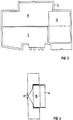
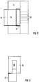
- FIGS. 4 to 6 show two side views and the top view in relation to FIG. 4 for a trigger magnet for a monitoring device for triggering the holding magnet in a series-connected residual current circuit breaker.
- the monitoring device 1 accommodates sensors 3 to 5 in its monitoring housing, specifically sensors 3 for the handle position of a circuit breaker to be added, a sensor 4 for the armature position and a sensor 5 for the contact position.
- the sensors can be designed according to the BERO principle.
- the sensors 3 to 5 and a value circuit are arranged on a circuit board 6 for monitoring. Understandably, the arrangement of the sensors depends on the design of a circuit breaker to be installed and monitored.
- a circuit board 7 with a circuit for bus coupling is arranged in the lower area. Contact with bus conductors is made via contact pins 8.
- a trigger unit 10 essentially a trigger magnet, and an associated driver mechanism 11 are provided in the monitoring device 1 according to FIG.
- the driver mechanism 11 can with a finger reaching through the monitoring housing 12 act on the mechanics of the key switch or the trigger of a circuit breaker to be connected.
- a shunt release for a fault current circuit breaker to be added is particularly simple and trouble-free in the monitoring device 1 according to FIG. 3.
- a release magnet 13 is arranged by arrangement and field guidance to specifically weaken the magnetic field of a holding magnet release in a fault current circuit breaker to be connected when the release magnet 13 is excited, so that the holding magnet release responds.
- Such a trigger magnet 13 can be designed, for example, as illustrated in FIGS. 4 to 6.
- a magnetic field coil 14 is arranged annularly and flattened around an imaginary axis 15.
- a core 16 engages in a magnet system as part of a ring core, which leads to pole shoes 17.
- the pole shoes 17 are advantageously designed in such a way that they emit a stray field to an adjacent plane in which the holding magnet release of a current protection switch to be lined up and monitored is positioned.
- the excitation for the magnetic field coil 14 can be controlled via a bus or via separate terminals for an external device. In both cases, the complete electrical and mechanical separation of the monitoring device and the monitored device is advantageous.
Landscapes
- Breakers (AREA)
- Driving Mechanisms And Operating Circuits Of Arc-Extinguishing High-Tension Switches (AREA)
- Rotary Switch, Piano Key Switch, And Lever Switch (AREA)
- Keying Circuit Devices (AREA)
Description
- Die Erfindung bezieht sich auf ein Überwachungsgerät zur Zustandserfassung bei elektromechanischen Schutzschaltern mit Schaltschloß, Schaltkontakten und Auslöseeinrichtung. Es ist bekannt, den Zustand von Schutzschaltern durch Sensoren von außen zu überwachen (US-A-4 706 073).
- Besonders in Bussystemen der Gebäudesystemtechnik möchte man zunehmend Schutzschaltsysteme und Einrichtungen wie Leitungsschutzschalter und Fehlerstromschutzschalter integrieren. Insbesondere soll eine Einbindung in das Bussystem der European Installation Bus Association, EIB-Bus, ermöglicht werden. Derzeitige Hilfsschalter für Leitungsschutzschalter oder Fehlerstromschutzschalter sind für den Anschluß an Bussysteme ungeeignet. Die Schaltkontakte und die elektromechanischen Bauteile von Schaltschloß und Auslöseeinrichtung sind für eine digitale Signalabgabe nicht eingerichtet. Andererseits wären Zusatzeinrichtungen mit Leitungsverbindungen zwischen dem Schutzschalter und einer Anbaueinheit der Störsicherheit abträglich.
- Darüber hinaus beeinträchtigt die in der Praxis bisher erforderliche Zuordnung von Hilfsschaltern und Fehlersignalschaltern zu einer Anbauseite des Schutzschalters und von Arbeitsstromauslösern für Fernauslösung zu einer anderen Anbauseite den weiteren Anbau eines Bausteins für Leitungsschutz bzw. für Schutz gegen Fehlerströme. Wenn das Grundgerät ein Leitungsschutzschalter ist, läßt sich also ein Anbauteil für Fehlerstromschutz bisher nicht anbauen, wenn Zusatzfunktionen der oben geschilderten Art anzubauen sind. Entsprechend ist die Situation, wenn man von einem Fehlerstromschutzschalter ausgeht und ein Anbauteil für Leitungsschutz vorsehen möchte.
- Der Erfindung liegt die Aufgabe zugrunde, die geschilderten Schwierigkeiten zu vermeiden und eine Ankopplung an ein Bussystem zu ermöglichen.
- Die Lösung der geschilderten Aufgabe erfolgt erfindungsgemäß durch ein Überwachungsgerät nach Patentanspruch 1. Bestimmte mechanische Zustände bei einem Leitungsschutzschalter oder Fehlerstromschutzschalter werden hierbei ohne mechanische Kopplung berührungslos durch das Gehäuse hindurch erfaßt. Vorteilhaft ist hierbei die Verschleißfreiheit und somit eine besonders geringe Störanfälligkeit, da berührungslose Sensoren, beispielsweise nach Art von BEROs, markante Bauteile in ihrer typischen Stellung überwachen können. Hierzu können Bauteile des Schaltschlosses oder der Auslöseeinrichtung überwacht werden oder auch etwa an diesen angebrachte zeigerartige Bauteile. Durch ohnehin erforderliche Auswerteelektronik zum Auswerten der berührungslos aufgenommenen Signale ist es durch Mehrfachnutzung von integrierten Schaltkreisbausteinen besonders wirtschaftlich, auch eine Busankopplung zur Anpassung an ein Bussystem und zur Übertragung in diesen unterzubringen.
- Beim Überwachungsgerät können in einfacher Weise die Sensoren im anreihbaren Überwachungsgehäuse benachbart zur Anbauwand angeordnet werden. Im Überwachungsgehäuse kann zusätzlich eine Auslöseeinheit angeordnet sein, die mit Koppelelementen zum Einwirken auf das Schaltschloß anzureihender Schutzschalter, gegebenenfalls über deren Auslöseeinheit, versehen ist. Die Funktionselemente in einem derartigen Überwachungsgehäuse erlauben nicht nur eine Zustandserfassung, sondern auch eine Einwirkung aufgrund von Befehlen, die über Busleiter übermittelt werden, auf denen das Überwachungsgerät aufgesetzt ist. Beispielsweise können die Busleiter in der Tragschiene zum Aufsetzen von Schutzschaltern untergebracht werden, so daß Schutzschalter und Überwachungsgerät angereiht auf derselben Tragschiene aufgesetzt sind, wobei die Busankopplung Hierzu kann im Überwachungsgehäuse eine Platine mit einer Schaltung zur Busankopplung angeordnet sein.
- Bei einem Überwachungsgehäuse für einen Fehlerstromschutzschalter kann die Auslöseeinheit im Überwachungsgerät lediglich als ein Elektromagnet ausgeführt sein, der mit Polschuhen in der Ausführung als Streufelderzeuger auf das Magnetsystem des Haltemagnetauslösers des Fehlerstromschutzschalters einwirkt. Bei geeigneter Positionierung und Bemessung des Elektromagneten kann das Magnetfeld des Haltemagnetauslösers bei Erregung des Elektromagneten so geschwächt werden, daß dessen Anker abfällt und der Fehlerstromschutzschalter auslöst.
- Die Erfindung soll nun anhand von in der Zeichnung grob schematisch wiedergegebenen Ausführungsbeispielen näher erläutert werden:
- In FIG 1 ist ein Überwachungsgerät zur Zustandserfassung in Schnittansicht veranschaulicht.
- In FIG 2 ist ein Überwachungsgerät in der Art nach FIG 1, jedoch mit zusätzlicher Auslöseeinheit für einen Leitungsschutzschalter wiedergegeben.
- In FIG 3 ist ein Überwachungsgerät mit einem Auslösemagneten für einen Fehlerstromschutzschalter dargestellt.
- In den Figuren 4 bis 6 sind zwei Seitenansichten und die Aufsicht bezogen auf FIG 4 bei einem Auslösemagneten für ein Überwachungsgerät zum Auslösen des Haltemagneten in einem angereihten Fehlerstromschutzschalter beispielhaft wiedergegeben.
- Das Überwachungsgerät 1 nach FIG 1 nimmt in seinem Überwachungsgehäuse 2 Sensoren 3 bis 5 auf, und zwar Sensoren 3 für die Griffstellung eines anzureihenden Schutzschalters, einen Sensor 4 für die Ankerstellung und einen Sensor 5 für die Kontaktstellung auf. Die Sensoren können nach dem BERO-Prinzip ausgeführt sein. Die Sensoren 3 bis 5 und eine werteschaltung sind auf einer Platine 6 für Überwachung angeordnet. Verständlicherweise richtet sich die Anordnung der Sensoren nach dem konstruktiven Aufbau eines anzureihenden und zu überwachenden Schutzschalters. Im unteren Bereich ist eine Platine 7 mit einer Schaltung zur Busankopplung angeordnet. Der Kontakt zu Busleitern erfolgt über Kontaktstifte 8.
- Um die Platine 6 für die Überwachung exakt zu positionieren, kann es vorteilhaft sein, Zentrierstifte 9 vorzusehen. Die Aufnehmer bzw. Sensoren 3 bis 5 sind dann für das zum Überwachen zugeordnete Gerät exakt positioniert.
- Um die Anbaufunktion "Arbeitsstromauslöser" zu realisieren, sind im Überwachungsgerät 1 nach FIG 2 eine Auslöseeinheit 10, im wesentlichen ein Auslösemagnet, und eine zugeordnete Mitnehmermechanik 11 vorgesehen. Die Mitnehmermechanik 11 kann mit einem das Überwachungsgehäuse durchgreifenden Finger 12 auf die Mechanik des Schaltschlosses oder des Auslösers eines anzureihenden Leitungsschutzschalters einwirken.
- Ein Arbeitsstromauslöser für einen anzureihenden Fehlerstromschutzschalter ist im Überwachungsgerät 1 nach FIG 3 besonders einfach und störungsfrei ausgeführt. Ein Auslösemagnet 13 ist durch Anordnung und Feldführung dafür eingerichtet, das Magnetfeld eines Haltemagnetauslösers in einem anzureihenden Fehlerstromschutzschalter bei Erregung des Auslösemagneten 13 gezielt zu schwächen, so daß der Haltemagnetauslöser anspricht.
- Ein derartiger Auslösemagnet 13 kann beispielsweise so ausgeführt sein, wie es in den Figuren 4 bis 6 veranschaulicht ist. Eine Magnetfeldspule 14 ist um eine gedachte Achse 15 ringförmig und flachgedrückt angeordnet. In einem Magnetsystem greift ein Kern 16 als Teil eines Ringkerns ein, der zu Polschuhen 17 führt. Die Polschuhe 17 sind vorteilhafterweise so gestaltet, daß sie ein Streufeld zu einer benachbarten Ebene abgeben, in der der Haltemagnetauslöser eines anzureihenden und zu überwachenden stromschutzschalters positioniert ist. Die Ansteuerung der Erregung für die Magnetfeldspule 14 kann über einen Bus oder über separate Klemmen für eine externe Einrichtung erfolgen. In beiden Fällen ist die vollständige galvanische und mechanische Trennung von Überwachungsgerät und überwachtem Gerät vorteilhaft.
Claims (4)
- Überwachungsgerät zur Zustandserfassung bei elektromechanischen Schutzschaltern, mit Schaltschloß, Schaltkontakten und Auslöseeinrichtung,
dadurch gekennzeichnet,
daß in einem zu Schutzschaltern anreihbaren Überwachungsgehäuse (2) in einem schmalen Raum in seinem oberen Bereich eine mit berührungslosen Sensoren (3, 4, 5) und einer Auswerteschaltung bestückte Platine (6) und in seinem unteren Bereich eine Platine (7) mit einer Schaltung zur Busankopplung angeordnet ist, wobei das Überwachungsgehäuse (2) das Profil von Schutzschaltern aufweist und Halterungen zum Aufschnappen auf eine Tragschiene ausgebildet sind. - Überwachungsgerät nach Anspruch 1,
dadurch gekennzeichnet,
daß die Sensoren (3, 4, 5) im Überwachunsgehäuse (2) benachbart zur Anbauwand für einen Schutzschalter angeordnet sind. - Überwachungsgerät nach Anspruch 1 oder 2,
dadurch gekennzeichnet,
daß im Überwachungsgehäuse (2) zusätzlich eine Auslöseeinheit (10) angeordnet ist, die mit Koppelelementen (Mitnehmermechanik 11, Durchgriffsfinger 12) zum Einwirken auf das Schaltschloß anzureihender Schutzschalter, gegebenenfalls über deren Auslöseeinheit, versehen ist. - Überwachungsgerät nach Anspruch 3,
dadurch gekennzeichnet,
daß bei einem Überwachungsgehäuse (2) für einen Fehlerstromschutzschalter die Auslöseeinheit (10) lediglich ein Elektromagnet mit Polschuhen (17) in der Ausführung als Streufelderzeuger ist.
Priority Applications (4)
| Application Number | Priority Date | Filing Date | Title |
|---|---|---|---|
| AT94108487T ATE158894T1 (de) | 1994-06-01 | 1994-06-01 | Überwachungsgerät zur zustandserfassung bei elektromechanischen schutzschaltern |
| DE59404211T DE59404211D1 (de) | 1994-06-01 | 1994-06-01 | Überwachungsgerät zur Zustandserfassung bei elektromechanischen Schutzschaltern |
| EP94108487A EP0685866B1 (de) | 1994-06-01 | 1994-06-01 | Überwachungsgerät zur Zustandserfassung bei elektromechanischen Schutzschaltern |
| CN95108563A CN1055174C (zh) | 1994-06-01 | 1995-06-01 | 机电式保护开关的状态监测设备 |
Applications Claiming Priority (1)
| Application Number | Priority Date | Filing Date | Title |
|---|---|---|---|
| EP94108487A EP0685866B1 (de) | 1994-06-01 | 1994-06-01 | Überwachungsgerät zur Zustandserfassung bei elektromechanischen Schutzschaltern |
Publications (2)
| Publication Number | Publication Date |
|---|---|
| EP0685866A1 EP0685866A1 (de) | 1995-12-06 |
| EP0685866B1 true EP0685866B1 (de) | 1997-10-01 |
Family
ID=8215987
Family Applications (1)
| Application Number | Title | Priority Date | Filing Date |
|---|---|---|---|
| EP94108487A Expired - Lifetime EP0685866B1 (de) | 1994-06-01 | 1994-06-01 | Überwachungsgerät zur Zustandserfassung bei elektromechanischen Schutzschaltern |
Country Status (4)
| Country | Link |
|---|---|
| EP (1) | EP0685866B1 (de) |
| CN (1) | CN1055174C (de) |
| AT (1) | ATE158894T1 (de) |
| DE (1) | DE59404211D1 (de) |
Families Citing this family (4)
| Publication number | Priority date | Publication date | Assignee | Title |
|---|---|---|---|---|
| DE19707729C2 (de) * | 1996-02-26 | 2000-05-11 | Siemens Ag | Elektromechanisches Schaltgerät |
| JP4358308B2 (ja) * | 1997-02-26 | 2009-11-04 | シーメンス アクチエンゲゼルシヤフト | 電気機械開閉器 |
| EP1150411A1 (de) * | 2000-04-25 | 2001-10-31 | Siemens Aktiengesellschaft | Unterspannungsauslöser |
| DE102013004094B4 (de) | 2012-06-22 | 2020-01-23 | Abb Ag | Hilfsschalter |
Family Cites Families (4)
| Publication number | Priority date | Publication date | Assignee | Title |
|---|---|---|---|---|
| US4112270A (en) * | 1977-09-02 | 1978-09-05 | Rys Tadeusz J | Means connecting circuit breaker and auxiliary feature modules |
| IN161314B (de) * | 1984-09-25 | 1987-11-07 | Oscar Vila Masot | |
| GB2247568A (en) * | 1990-08-30 | 1992-03-04 | Mk Electric Ltd | Circuitbreaker electrical control apparatus |
| DE9406897U1 (de) * | 1993-04-26 | 1994-06-16 | Siemens AG, 80333 München | Installationssystem |
-
1994
- 1994-06-01 EP EP94108487A patent/EP0685866B1/de not_active Expired - Lifetime
- 1994-06-01 AT AT94108487T patent/ATE158894T1/de not_active IP Right Cessation
- 1994-06-01 DE DE59404211T patent/DE59404211D1/de not_active Expired - Lifetime
-
1995
- 1995-06-01 CN CN95108563A patent/CN1055174C/zh not_active Expired - Fee Related
Also Published As
| Publication number | Publication date |
|---|---|
| EP0685866A1 (de) | 1995-12-06 |
| CN1118929A (zh) | 1996-03-20 |
| ATE158894T1 (de) | 1997-10-15 |
| DE59404211D1 (de) | 1997-11-06 |
| CN1055174C (zh) | 2000-08-02 |
Similar Documents
| Publication | Publication Date | Title |
|---|---|---|
| DE19511795A1 (de) | Elektromechanisches Schaltgerät | |
| EP0156184A2 (de) | Zusatzbaustein für einen Leistungsschalter mit einem Arbeitsstromauslöser | |
| EP3270399B1 (de) | Testvorrichtung zum automatischen überprüfen der funktionsfähigkeit eines schutzschalters | |
| WO2014015947A2 (de) | Vorrichtung zum sicheren schalten einer photovoltaikanlage | |
| DE202011051667U1 (de) | Vorrichtung zur Positionserfassung einer Aufzugkabine | |
| EP0685866A1 (de) | Verfahren und Überwachungsgerät zur Zustandserfassung bei elektromechanischen Schutzschaltern | |
| EP3761335B1 (de) | Elektronisches schaltgerät | |
| EP0114231A1 (de) | Überstromschutz | |
| DE3823101A1 (de) | Redundante ausloeseeinrichtung | |
| EP2899823B1 (de) | Elektrische Schutzanordnung für eine Elektroinstallation sowie dazugehöriges Verfahren | |
| EP0637785B1 (de) | Koppeladapter zum Anschliessen eines Schutzschalters an einem Bus | |
| DE3905422A1 (de) | Vorrichtung zur induktiven abfrage und energieversorgung eines isolierten stromkreises mit elektrischem verbraucher | |
| EP2471084B1 (de) | Aufsatzmodul zum erfassen eines schaltzustandes eines elektromagnetischen schaltgeräts | |
| DE19809709A1 (de) | Vorrichtung zum Überwachen eines Schutzbereichs | |
| DE19543212A1 (de) | Fehlerstromschutzschalter | |
| DE19707729C2 (de) | Elektromechanisches Schaltgerät | |
| DE102019220444B4 (de) | Fernantrieb und Parametrier-Verfahren | |
| DE102022212034B4 (de) | Hilfsschalter für einen elektrischen Schalter und elektrischer Schalter mit solch einem Hilfsschalter | |
| DE9406897U1 (de) | Installationssystem | |
| DE202004002714U1 (de) | Stromkreisüberwachungseinrichtung | |
| DE3884179T2 (de) | Steuerrelais mit steckbaren Messfühler. | |
| EP1005710B1 (de) | Fehlerstromschutzschalter | |
| DE102023200638B3 (de) | Zubehör für einen elektrischen Schalter und elektrischer Schalter mit solch einem Zubehör | |
| KR20020044660A (ko) | 누전차단기의 누전 테스트장치 | |
| DE3141661A1 (de) | Einrichtung zur ueberwachung von stromkreisen |
Legal Events
| Date | Code | Title | Description |
|---|---|---|---|
| PUAI | Public reference made under article 153(3) epc to a published international application that has entered the european phase |
Free format text: ORIGINAL CODE: 0009012 |
|
| 17P | Request for examination filed |
Effective date: 19950424 |
|
| AK | Designated contracting states |
Kind code of ref document: A1 Designated state(s): AT CH DE FR GB IT LI |
|
| 17Q | First examination report despatched |
Effective date: 19960326 |
|
| GRAG | Despatch of communication of intention to grant |
Free format text: ORIGINAL CODE: EPIDOS AGRA |
|
| GRAH | Despatch of communication of intention to grant a patent |
Free format text: ORIGINAL CODE: EPIDOS IGRA |
|
| GRAH | Despatch of communication of intention to grant a patent |
Free format text: ORIGINAL CODE: EPIDOS IGRA |
|
| RIN1 | Information on inventor provided before grant (corrected) |
Inventor name: KLEEMEIER, MANFRED Inventor name: FINGER, HANS-GEORG |
|
| GRAA | (expected) grant |
Free format text: ORIGINAL CODE: 0009210 |
|
| AK | Designated contracting states |
Kind code of ref document: B1 Designated state(s): AT CH DE FR GB IT LI |
|
| REF | Corresponds to: |
Ref document number: 158894 Country of ref document: AT Date of ref document: 19971015 Kind code of ref document: T |
|
| REG | Reference to a national code |
Ref country code: CH Ref legal event code: NV Representative=s name: SIEMENS SCHWEIZ AG Ref country code: CH Ref legal event code: EP |
|
| REF | Corresponds to: |
Ref document number: 59404211 Country of ref document: DE Date of ref document: 19971106 |
|
| ET | Fr: translation filed | ||
| GBT | Gb: translation of ep patent filed (gb section 77(6)(a)/1977) |
Effective date: 19971112 |
|
| ITF | It: translation for a ep patent filed | ||
| PLBE | No opposition filed within time limit |
Free format text: ORIGINAL CODE: 0009261 |
|
| STAA | Information on the status of an ep patent application or granted ep patent |
Free format text: STATUS: NO OPPOSITION FILED WITHIN TIME LIMIT |
|
| 26N | No opposition filed | ||
| REG | Reference to a national code |
Ref country code: GB Ref legal event code: IF02 |
|
| PGFP | Annual fee paid to national office [announced via postgrant information from national office to epo] |
Ref country code: AT Payment date: 20020529 Year of fee payment: 9 |
|
| PG25 | Lapsed in a contracting state [announced via postgrant information from national office to epo] |
Ref country code: AT Free format text: LAPSE BECAUSE OF NON-PAYMENT OF DUE FEES Effective date: 20030601 |
|
| PGFP | Annual fee paid to national office [announced via postgrant information from national office to epo] |
Ref country code: GB Payment date: 20030611 Year of fee payment: 10 |
|
| PGFP | Annual fee paid to national office [announced via postgrant information from national office to epo] |
Ref country code: CH Payment date: 20030905 Year of fee payment: 10 |
|
| PG25 | Lapsed in a contracting state [announced via postgrant information from national office to epo] |
Ref country code: GB Free format text: LAPSE BECAUSE OF NON-PAYMENT OF DUE FEES Effective date: 20040601 |
|
| PG25 | Lapsed in a contracting state [announced via postgrant information from national office to epo] |
Ref country code: LI Free format text: LAPSE BECAUSE OF NON-PAYMENT OF DUE FEES Effective date: 20040630 Ref country code: CH Free format text: LAPSE BECAUSE OF NON-PAYMENT OF DUE FEES Effective date: 20040630 |
|
| GBPC | Gb: european patent ceased through non-payment of renewal fee | ||
| REG | Reference to a national code |
Ref country code: CH Ref legal event code: PL |
|
| PGFP | Annual fee paid to national office [announced via postgrant information from national office to epo] |
Ref country code: IT Payment date: 20110627 Year of fee payment: 18 |
|
| PG25 | Lapsed in a contracting state [announced via postgrant information from national office to epo] |
Ref country code: IT Free format text: LAPSE BECAUSE OF NON-PAYMENT OF DUE FEES Effective date: 20120601 |
|
| PGFP | Annual fee paid to national office [announced via postgrant information from national office to epo] |
Ref country code: FR Payment date: 20130703 Year of fee payment: 20 |
|
| PGFP | Annual fee paid to national office [announced via postgrant information from national office to epo] |
Ref country code: DE Payment date: 20130819 Year of fee payment: 20 |
|
| REG | Reference to a national code |
Ref country code: DE Ref legal event code: R071 Ref document number: 59404211 Country of ref document: DE |
|
| PG25 | Lapsed in a contracting state [announced via postgrant information from national office to epo] |
Ref country code: DE Free format text: LAPSE BECAUSE OF EXPIRATION OF PROTECTION Effective date: 20140603 |