EP0684482A2 - Analyseverfahren und -instrument mit Abtastsignal - Google Patents
Analyseverfahren und -instrument mit Abtastsignal Download PDFInfo
- Publication number
- EP0684482A2 EP0684482A2 EP95202205A EP95202205A EP0684482A2 EP 0684482 A2 EP0684482 A2 EP 0684482A2 EP 95202205 A EP95202205 A EP 95202205A EP 95202205 A EP95202205 A EP 95202205A EP 0684482 A2 EP0684482 A2 EP 0684482A2
- Authority
- EP
- European Patent Office
- Prior art keywords
- filter
- sweep
- under test
- intermediate frequency
- network
- Prior art date
- Legal status (The legal status is an assumption and is not a legal conclusion. Google has not performed a legal analysis and makes no representation as to the accuracy of the status listed.)
- Withdrawn
Links
- 238000000034 method Methods 0.000 title claims abstract description 18
- 238000010408 sweeping Methods 0.000 claims abstract description 18
- 230000004044 response Effects 0.000 claims description 36
- 230000006870 function Effects 0.000 claims description 19
- 238000012360 testing method Methods 0.000 claims description 17
- 238000012546 transfer Methods 0.000 claims description 13
- 238000001914 filtration Methods 0.000 claims description 10
- 230000006872 improvement Effects 0.000 claims description 7
- 230000001419 dependent effect Effects 0.000 claims description 5
- 238000003012 network analysis Methods 0.000 claims 1
- 238000012805 post-processing Methods 0.000 abstract description 4
- 238000001228 spectrum Methods 0.000 description 13
- 230000007423 decrease Effects 0.000 description 7
- 238000013459 approach Methods 0.000 description 5
- 238000010586 diagram Methods 0.000 description 4
- 230000000694 effects Effects 0.000 description 4
- 238000006243 chemical reaction Methods 0.000 description 3
- 238000005259 measurement Methods 0.000 description 3
- 230000007246 mechanism Effects 0.000 description 3
- 238000010897 surface acoustic wave method Methods 0.000 description 3
- 230000015556 catabolic process Effects 0.000 description 2
- 239000013078 crystal Substances 0.000 description 2
- 238000006731 degradation reaction Methods 0.000 description 2
- 238000009795 derivation Methods 0.000 description 2
- 230000005284 excitation Effects 0.000 description 2
- 238000010606 normalization Methods 0.000 description 2
- 230000035945 sensitivity Effects 0.000 description 2
- 230000003595 spectral effect Effects 0.000 description 2
- 230000004075 alteration Effects 0.000 description 1
- 239000003990 capacitor Substances 0.000 description 1
- 230000008859 change Effects 0.000 description 1
- 238000005094 computer simulation Methods 0.000 description 1
- 238000013461 design Methods 0.000 description 1
- 238000005516 engineering process Methods 0.000 description 1
- 230000000737 periodic effect Effects 0.000 description 1
- 238000004088 simulation Methods 0.000 description 1
- 238000010183 spectrum analysis Methods 0.000 description 1
- 230000007480 spreading Effects 0.000 description 1
- 230000001360 synchronised effect Effects 0.000 description 1
- 230000001052 transient effect Effects 0.000 description 1
- 230000004304 visual acuity Effects 0.000 description 1
Images

Classifications
-
- G—PHYSICS
- G01—MEASURING; TESTING
- G01R—MEASURING ELECTRIC VARIABLES; MEASURING MAGNETIC VARIABLES
- G01R27/00—Arrangements for measuring resistance, reactance, impedance, or electric characteristics derived therefrom
- G01R27/28—Measuring attenuation, gain, phase shift or derived characteristics of electric four pole networks, i.e. two-port networks; Measuring transient response
- G01R27/30—Measuring attenuation, gain, phase shift or derived characteristics of electric four pole networks, i.e. two-port networks; Measuring transient response with provision for recording characteristics, e.g. by plotting Nyquist diagram
-
- G—PHYSICS
- G01—MEASURING; TESTING
- G01R—MEASURING ELECTRIC VARIABLES; MEASURING MAGNETIC VARIABLES
- G01R23/00—Arrangements for measuring frequencies; Arrangements for analysing frequency spectra
- G01R23/02—Arrangements for measuring frequency, e.g. pulse repetition rate; Arrangements for measuring period of current or voltage
- G01R23/14—Arrangements for measuring frequency, e.g. pulse repetition rate; Arrangements for measuring period of current or voltage by heterodyning; by beat-frequency comparison
-
- G—PHYSICS
- G01—MEASURING; TESTING
- G01R—MEASURING ELECTRIC VARIABLES; MEASURING MAGNETIC VARIABLES
- G01R23/00—Arrangements for measuring frequencies; Arrangements for analysing frequency spectra
- G01R23/16—Spectrum analysis; Fourier analysis
- G01R23/173—Wobbulating devices similar to swept panoramic receivers
Definitions
- the present invention relates to swept signal analysis instruments, such as spectrum analyzers and network analyzers, and more particularly relates to a method and apparatus permitting such instruments to be swept at fast rates.
- swept signal analysis instrument as used herein is a generic term referring to any electronic equipment in which an input signal is mixed to an intermediate frequency using a swept local oscillator and is subsequently filtered.
- swept signal analysis instruments are spectrum analyzers and network analyzers, and it is with reference to these instruments that the present invention is illustrated.
- a spectrum analyzer an input signal to be analyzed is heterodyned to an intermediate frequency (IF) using a swept local oscillator.
- the IF signal is filtered with a narrow bandwidth IF filter.
- the swept local oscillator has the effect of "sweeping" all the frequencies of the heterodyned-down input signal past the fixed frequency of the IF filter, thereby permitting the filter to resolve the input signal's spectral composition.
- the signal power within the filter bandwidth is determined by a detector cascaded after the IF filter and is typically displayed on a graphical display associated with the instrument.
- a network analyzer is similar in many respects to a spectrum analyzer but instead of analyzing an unknown signal, the instrument analyzes an unknown network. To do this, the instrument excites the unknown network with a known signal and monitors the phase and amplitude characteristics of a resultant signal, thereby permitting the network's transfer function to be characterized. Again, the instrument relies on a swept local oscillator to heterodyne the input signal to an intermediate frequency, and the IF signal is again filtered prior to analysis. In a network analyzer, however, the IF filter serves to eliminate noise effects rather than to provide a narrow resolution bandwidth, and the filtered IF signal is analyzed to determine the phase and amplitude of the IF signal rather than its power. The analysis further includes "normalizing" the IF signal to the original excitation signal in order to reduce excitation source related errors.
- An ideal Gaussian response is often approximated by cascading a plurality of single-tuned filter stages.
- These cascaded stages generally include capacitors, inductors or crystals, and thus have transfer functions with poles. All transfer functions with poles exhibit non-flat group delay, also known as nonlinear phase response.
- One problem with such filters is that they respond more quickly to the leading edge of an input transient signal than the trailing edge.
- Another problem is that the trailing edge often exhibits notches and ringing rather than a smooth fall to the noise floor. Small signals are difficult to differentiate from aberrations on the falling edge of nearby larger signals.
- sweep related errors manifest themselves as errors in normalization and as irregularities in both the frequency and phase response of the noise limiting filter. Again, these errors increase with sweep speed and limit the maximum rate at which a network analyzer can sweep through a frequency range of interest.
- the sweep rate limitations that heretofore have constrained the maximum sweep rates of swept analysis instruments are obviated by optimizing the filter circuitry and post-processing the IF signal using various techniques to compensate for fast sweeping errors.
- Improved filters with close to Gaussian magnitude response and flat group delay, may be "overswept.”
- the amplitude of stationary signals decreases in a predictable manner that is a function of the bandwidth and the sweep rate, and that amplitude change may be used as compensation to provide accurate amplitude measurements.
- Fig. 1 shows several bandwidths of Gaussian filter over several decades of sweep rate. The effect of different sweep rates and bandwidths on signal to noise ratio can readily be seen.
- a further aspect of swept spectrum analysis that is improved by this invention is frequency resolution of signals. Improved resolution means being able to differentiate signals that are closer together.
- a useful concept to introduce is that of "apparent resolution.” This is defined as the bandwidth of the swept response at some appropriate level below the peak response.
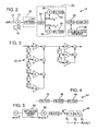
- a spectrum analyzer 10 includes an analog input 12, a mixer 14 with an associated swept local oscillator 16, an analog IF chain 18, analog-to-quadrature digital conversion circuitry 20, and post-processing circuitry 22.
- the analog IF chain 18 includes an IF filter 24 that sets the resolution bandwidth of the analyzer. According to one embodiment of the present invention, the behavior of this filter is optimized by improving its phase response and group delay characteristics.
- filter 24 may take several forms.
- the filter is implemented in analog form, with cascaded lumped elements or crystals, or surface acoustic wave technology. Such filters can be equalized to yield magnitude response close to Gaussian, effectively eliminating unacceptable responses that cause distortions in the detected spectrum.
- the filter is implemented in a finite-impulse- response (FIR) design, thereby achieving perfectly flat group delay. (In this latter embodiment, of course, the IF signal must be converted into digital form prior to filtering.) Again, nearly Gaussian response can be obtained, thereby greatly reducing filter-induced distortion mechanisms.
- FIR finite-impulse- response
- the analog-to-quadrature digital conversion circuitry 20 includes an analog-to-digital converter circuit 26, a pair of mixers 28, 30, and a corresponding pair of low pass filters 32, 34 (which preferably have a linear phase [flat group delay] characteristic).
- the analog-to-digital converter 26 samples the IF signal at periodic intervals and outputs a series of digital data samples corresponding thereto. These digital samples are multiplied with sin " ,t and coswt signals by the mixers 28, 30 to yield digital representations of the real and imaginary components of the IF signal.
- Linear-phase (or flat group delay) filters 32, 34 filter the quadrature signals at baseband, equivalent to providing a linear-phase (or flat group delay) filter centered at the frequency WIF/2-ff Hz.
- Quadrature analog-to-quadrature digital conversion circuitry 20 is generally known in the art, as described, inter alia, in U.S. Patent 4,594,555, the disclosure of which is incorporated herein by reference.
- the filters 32, 34 in the illustrated embodiment are implemented digitally, as shown in Fig. 3.
- the tap coefficients are selected to be powers of two, thereby permitting the use of bit shifters instead of multiplier stages.
- Each filter is implemented with 24-bit logic and a sample clock rate of 250 KHz to provide a filter bandwidth of 18KHz.
- Narrower filter widths can be achieved by filtering the IF signal repeatedly through IF filter 24, effectively halving the data bandwidth and sample rate for each pass through the filter.
- filters 32, 34 can alternatively be implemented in analog form, if desired.
- the analyzer will still exhibit an amplitude decrease of about 0.1 dB when swept at .5BW 2 , and more at faster rates.
- This amplitude decrease can be corrected by predicting the loss and applying a compensating sweep-dependent gain.
- the gain can be applied any place in the signal path.
- the compensating gain is applied in a CPU controlled post-processing stage 22 that may include a calibration memory 36.
- the required compensation can be predicted in at least three ways. In the first, it can be computed using the solution of a swept Gaussian response. This approach is attractive because the solution exists in closed-form equations (as shown in the Tsakiris paper, supra) and is thus computationally efficient.
- the required compensation can be simulated, such as by using a computer model of the actual filter. This approach is more precise than approximating the true filter response as Gaussian, but is more computationally intensive. However, simulations can be performed at a number of sweep rates, and the compensations saved in a table for later use. Compensations for sweep rates other than the ones simulated can be interpolated from the values in the table.
- the required compensation can be actually measured in the spectrum analyzer system. This can be done by sweeping through a known amplitude signal at the desired rate and measuring the decrease in amplitude. This is attractive because it takes variations in each individual instrument into account. Again, interpolation can be used to minimize the number of measurements that have to be made.
- the fast sweeping also introduces an apparent frequency shift in the resulting data.
- This frequency shift can also be predicted (either in closed mathematical form [the formula is given in the Tsakiris paper]) or by one of the other techniques noted above. Once predicted, it can similarly be compensated for.
- the above-described embodiment provides several improvements to the art.
- One is the use of approximately gaussian filters of linear phase to a signal analysis instrument. While the amplitude response of such a filter may not be a substantial improvement over prior art cascaded synchronous single-tuned filter stages, the phase response is. That is, the linear-phase filtering employed in the illustrative embodiment offers the instrument a symmetric passband with essentially no ringing under dynamic conditions.
- the Tsakiris article indicates that asymmetric passband and dynamic ringing are unavoidable in such instruments.
- Another improvement is the improved sensitivity and resolving power that can be achieved by "oversweeping" using a smaller than traditional bandwidth. Again, the Tsakiris article indicates that fast sweeping is to be avoided because it leads to a degradation of resolution and sensitivity.
- the IF filter 24 can be implemented using a conventional arrangement of a plurality of cascaded single tuned filter stages 38, as shown by filter 24' in Fig. 4.
- the resulting amplitude loss can again be predicted using any of the three methods detailed above and can be compensated accordingly.
- the cascaded stages exhibit a non-flat group delay, the filter also introduces a time delay, which translates into a frequency offset. This error term, too, can be predicted and corrected.
- the error mechanisms include errors in normalization of the network output signal due to fast sweeping, and the errors caused by sweeping through the parabolic phase characteristic of the instrument's IF (aka noise limiting) filter. These error mechanisms can be determined and compensated, as detailed in Appendix F.
- Fig. 5 shows a network analyzer 38 used to analyze a network under test 40.
- the analyzer 38 includes a swept mixer 42, an IF filter 44, and a simple 3-tap FIR filter 46 cascaded after IF filter 44 to mitigate the effects of parabolic phase errors.
- the coefficients (symmetrical) for the filter 46 are given by the following formulas:
- More complex filter topologies i.e. more taps
- more taps can be used to yield commensurately better error compensation.
- Another technique of compensating for the parabolic phase error is to add the results an increasing-frequency sweep to the conjugate of a corresponding decreasing-frequency sweep.
- Yet another technique to equalize the parabolic phase error is to perform a Fourier transform on the raw data, multiply by a parabolic phase term, and then perform an inverse Fourier transform.
- a final technique to compensate the parabolic phase error is by use of a parallel filter equalizer.
- the analyzer filter 44 windows the frequency transform of the network under test.
- the shape of this windowing function can be selected to optimize fast sweep speed performance.
- the filter should be flat to give a uniform window.
- a variety of other windowing functions are advantageous for different circumstances. Accordingly, it is desirable to provide the instrument with a plurality of windowing functions and means for selecting therebetween.
- the preferred implementation is to provide a single filter and to implement the different windowing functions digitally. (Window selection is known in digital signal analyzers, but has not heretofore been employed in network analyzers.)
- a desirable filter is the Nyquist zero symbol interference filter.
Landscapes
- Physics & Mathematics (AREA)
- General Physics & Mathematics (AREA)
- Mathematical Physics (AREA)
- Measurement Of Resistance Or Impedance (AREA)
- Measuring Frequencies, Analyzing Spectra (AREA)
Applications Claiming Priority (3)
| Application Number | Priority Date | Filing Date | Title |
|---|---|---|---|
| US493590 | 1990-03-13 | ||
| US07/493,590 US5117179A (en) | 1990-03-13 | 1990-03-13 | Swept signal analysis instrument and method |
| EP19910302059 EP0451955A3 (en) | 1990-03-13 | 1991-03-12 | Swept signal analysis instrument and method |
Related Parent Applications (1)
| Application Number | Title | Priority Date | Filing Date |
|---|---|---|---|
| EP91302059.0 Division | 1991-03-12 |
Publications (1)
| Publication Number | Publication Date |
|---|---|
| EP0684482A2 true EP0684482A2 (de) | 1995-11-29 |
Family
ID=23960873
Family Applications (2)
| Application Number | Title | Priority Date | Filing Date |
|---|---|---|---|
| EP19910302059 Withdrawn EP0451955A3 (en) | 1990-03-13 | 1991-03-12 | Swept signal analysis instrument and method |
| EP95202205A Withdrawn EP0684482A2 (de) | 1990-03-13 | 1991-03-12 | Analyseverfahren und -instrument mit Abtastsignal |
Family Applications Before (1)
| Application Number | Title | Priority Date | Filing Date |
|---|---|---|---|
| EP19910302059 Withdrawn EP0451955A3 (en) | 1990-03-13 | 1991-03-12 | Swept signal analysis instrument and method |
Country Status (3)
| Country | Link |
|---|---|
| US (3) | US5117179A (de) |
| EP (2) | EP0451955A3 (de) |
| JP (1) | JPH04221777A (de) |
Families Citing this family (19)
| Publication number | Priority date | Publication date | Assignee | Title |
|---|---|---|---|---|
| US5117179A (en) * | 1990-03-13 | 1992-05-26 | Hewlett-Packard Company | Swept signal analysis instrument and method |
| US5463893A (en) * | 1994-05-16 | 1995-11-07 | General Electric Company | Sensor matching through real-time output compensation |
| DE19522613C1 (de) * | 1995-06-22 | 1996-10-10 | Rohde & Schwarz | Netzwerkanalysator |
| US6018246A (en) * | 1997-10-17 | 2000-01-25 | Hewlett-Packard Company | Network analyzer measurement method for high dynamic range devices |
| JP3338370B2 (ja) * | 1998-05-14 | 2002-10-28 | 株式会社アドバンテスト | 周波数分析方法及びこの方法を用いた掃引型スペクトラム・アナライザ |
| JP3797556B2 (ja) * | 2000-10-02 | 2006-07-19 | 株式会社アドバンテスト | 周波数変換掃引測定方法 |
| US6700366B2 (en) * | 2002-02-05 | 2004-03-02 | Anritsu Company | Very fast swept spectrum analyzer |
| US6617856B1 (en) * | 2002-02-15 | 2003-09-09 | Radiodetection Limited | Electronic marker locator system and method |
| US7050918B2 (en) * | 2002-10-07 | 2006-05-23 | Lecroy Corporation | Digital group delay compensator |
| JP2006511987A (ja) * | 2002-10-07 | 2006-04-06 | レクロイ コーポレーション | デジタル群遅延補正器 |
| US7058528B2 (en) * | 2003-07-11 | 2006-06-06 | Ionalytics Corporation | Automated optimization of asymmetric waveform generator LC tuning electronics |
| DE102004050912B4 (de) * | 2004-04-05 | 2009-09-10 | Rohde & Schwarz Gmbh & Co. Kg | Verfahren und Vorrichtung zur Erhöhung des Dynamikbereichs und der Meßgenauigkeit einer Meßeinrichtung zur Spektrum- und/oder Netzwerkanalyse |
| DE102004020278A1 (de) * | 2004-04-26 | 2005-11-10 | Rohde & Schwarz Gmbh & Co. Kg | Spektrumanalysator mit hoher Geschwindigkeit und gleichzeitig hoher Auflösung |
| US7054780B2 (en) * | 2004-09-13 | 2006-05-30 | Agilent Technologies, Inc. | Network analyzer applying loss compensation using port extensions and method of operation |
| DE102004047042A1 (de) * | 2004-09-28 | 2006-04-06 | Rohde & Schwarz Gmbh & Co Kg | Verfahren und Vorrichtung zur Spektrumanalyse eines Nutz- oder Rauschsignals |
| CN101180796A (zh) * | 2005-06-16 | 2008-05-14 | 神经网路处理有限公司 | 插补处理电路 |
| JP5940389B2 (ja) * | 2012-06-25 | 2016-06-29 | 日置電機株式会社 | 交流抵抗測定装置および交流抵抗測定方法 |
| US9959883B2 (en) * | 2015-10-06 | 2018-05-01 | The Trustees Of Princeton University | Method and system for producing low-noise acoustical impulse responses at high sampling rate |
| RU2670702C9 (ru) * | 2017-11-08 | 2018-11-28 | Федеральное государственное бюджетное учреждение науки Институт проблем управления им. В.А. Трапезникова Российской академии наук | Способ кратковременного спектрального анализа квазистационарных сигналов |
Citations (2)
| Publication number | Priority date | Publication date | Assignee | Title |
|---|---|---|---|---|
| US4594555A (en) | 1984-10-29 | 1986-06-10 | Hewlett-Packard Company | Frequency selective sampling detector |
| US4881191A (en) | 1987-01-13 | 1989-11-14 | Hewlett-Packard Company | Multichannel decimation/interpolation filter |
Family Cites Families (17)
| Publication number | Priority date | Publication date | Assignee | Title |
|---|---|---|---|---|
| NL182171C (nl) * | 1952-09-12 | Delta Nederland B V | Collectorzonweringsstelsel. | |
| US2996667A (en) * | 1959-12-18 | 1961-08-15 | Bell Telephone Labor Inc | Spectrum analyzer |
| US3364426A (en) * | 1965-01-14 | 1968-01-16 | Hyman Hurvitz | Double channel spectrum analyzer |
| US3617948A (en) * | 1969-09-17 | 1971-11-02 | Bell Telephone Labor Inc | Transversal equalizer modified for signal filtering |
| US3633111A (en) * | 1969-10-22 | 1972-01-04 | Gen Motors Corp | Signal-seeking radio receiver |
| US3916319A (en) * | 1974-06-19 | 1975-10-28 | Hewlett Packard Co | Adaptive sweep generator for a spectrum analyzer |
| US4524424A (en) * | 1982-02-18 | 1985-06-18 | Rockwell International Corporation | Adaptive spectrum shaping filter |
| DD215870A1 (de) * | 1983-05-09 | 1984-11-21 | Adw Ddr | Radaranlage starker signalkompression mit verbessertem aufloesungsvermoegen |
| JPH0619390B2 (ja) * | 1985-08-08 | 1994-03-16 | 横河・ヒユ−レツト・パツカ−ド株式会社 | デイジタル・フ−リエ変換の後処理方法 |
| US4914600A (en) * | 1987-06-05 | 1990-04-03 | Gruman Aerospace Corporation | Programmable frequency identifier circuit |
| US4995006A (en) * | 1988-03-31 | 1991-02-19 | Wiltron Company | Apparatus and method for low-pass equivalent processing |
| US4896102A (en) * | 1988-06-13 | 1990-01-23 | Scientific-Atlanta, Inc. | Spectrum analyzer |
| US5065334A (en) * | 1989-04-28 | 1991-11-12 | Hewlett-Packard Company | Method and apparatus for distinguishing narrowband continuous wave signals from broadband and impulsive signals |
| US4994740A (en) * | 1989-09-25 | 1991-02-19 | The United States Of America As Represented By The Secretary Of The Army | High resolution, wide band Chirp-Z signal analyzer |
| US5099200A (en) * | 1990-01-12 | 1992-03-24 | Hewlett-Packard Company | I.f. calibration system |
| US5168213A (en) * | 1990-03-13 | 1992-12-01 | Hewlett-Packard Company | Swept signal analysis instrument and method |
| US5117179A (en) * | 1990-03-13 | 1992-05-26 | Hewlett-Packard Company | Swept signal analysis instrument and method |
-
1990
- 1990-03-13 US US07/493,590 patent/US5117179A/en not_active Expired - Lifetime
-
1991
- 1991-03-12 EP EP19910302059 patent/EP0451955A3/en not_active Withdrawn
- 1991-03-12 EP EP95202205A patent/EP0684482A2/de not_active Withdrawn
- 1991-03-13 JP JP3073909A patent/JPH04221777A/ja active Pending
-
1992
- 1992-11-19 US US07/978,551 patent/US5300878A/en not_active Expired - Lifetime
-
1994
- 1994-02-07 US US08/192,927 patent/US5420514A/en not_active Expired - Lifetime
Patent Citations (2)
| Publication number | Priority date | Publication date | Assignee | Title |
|---|---|---|---|---|
| US4594555A (en) | 1984-10-29 | 1986-06-10 | Hewlett-Packard Company | Frequency selective sampling detector |
| US4881191A (en) | 1987-01-13 | 1989-11-14 | Hewlett-Packard Company | Multichannel decimation/interpolation filter |
Non-Patent Citations (1)
| Title |
|---|
| TSAKIRIS: "Resolution of a Spectrum Analyzer UNder Dynamic Operating Conditions", REV. SCI. INSTRUM., vol. 48, no. 11, November 1977 (1977-11-01) |
Also Published As
| Publication number | Publication date |
|---|---|
| JPH04221777A (ja) | 1992-08-12 |
| US5300878A (en) | 1994-04-05 |
| US5420514A (en) | 1995-05-30 |
| EP0451955A3 (en) | 1992-10-14 |
| US5117179A (en) | 1992-05-26 |
| EP0451955A2 (de) | 1991-10-16 |
Similar Documents
| Publication | Publication Date | Title |
|---|---|---|
| US5117179A (en) | Swept signal analysis instrument and method | |
| US6700366B2 (en) | Very fast swept spectrum analyzer | |
| Andria et al. | Windows and interpolation algorithms to improve electrical measurement accuracy | |
| US6512788B1 (en) | RF output spectrum measurement analyzer and method | |
| US5706202A (en) | Frequency spectrum analyzing apparatus and transmitter characteristics measuring apparatus using the same | |
| US7711510B2 (en) | Method of crossover region phase correction when summing signals in multiple frequency bands | |
| EP1914899B1 (de) | Frequenzgangkorrektur für einen Empfänger mit Frequenzumsetzungsvorrichtung | |
| CN111788782B (zh) | 用于测量距无源互调源的距离的方法和设备 | |
| JPH0750136B2 (ja) | 周波数測定方法 | |
| US5168213A (en) | Swept signal analysis instrument and method | |
| US20200072813A1 (en) | Probing a structure of concrete by means of electromagnetic waves | |
| Lobov et al. | Digital compensation for uneven frequency response of analog filters from the hybrid filter bank | |
| CN117538588B (zh) | 一种幅频响应和相频响应的补偿装置、补偿方法及示波器 | |
| JP3122144B2 (ja) | 計器の中間周波数応答特性を得る方法 | |
| US7791329B2 (en) | Vector/signal analyzer equalization apparatus and method | |
| US4417310A (en) | Apparatus for measuring distortion factor | |
| KR101294771B1 (ko) | 크기 측정 데이터를 이용하는 필터 등화 | |
| US7425908B2 (en) | Method of generating a digital signal that is representative of match errors in an analog digital conversion system with the time interleaving, and an analog digital converter with time interleaving using same | |
| JP2000180484A (ja) | 高調波測定装置 | |
| US8023534B2 (en) | Signal processor latency measurement | |
| EP1916533A1 (de) | Charakterisierung eines Frequenzgangs für eine Frequenzumsetzungsvorrichtung | |
| EP1026509B1 (de) | Verfahren und Vorrichtung zum Feststellen von Oberwellen in einem elektrischen Netz | |
| JPH10126217A (ja) | デシメーションフィルタ | |
| US20070112532A1 (en) | Method of crossover region phase correction when summing signals in multiple frequency bands | |
| EP1367402A1 (de) | Verfahren und Anordnung zur Phasenmessung eines modulierten RF-Signals |
Legal Events
| Date | Code | Title | Description |
|---|---|---|---|
| PUAI | Public reference made under article 153(3) epc to a published international application that has entered the european phase |
Free format text: ORIGINAL CODE: 0009012 |
|
| AC | Divisional application: reference to earlier application |
Ref document number: 451955 Country of ref document: EP |
|
| AK | Designated contracting states |
Kind code of ref document: A2 Designated state(s): DE FR GB IT |
|
| STAA | Information on the status of an ep patent application or granted ep patent |
Free format text: STATUS: THE APPLICATION HAS BEEN WITHDRAWN |
|
| 18W | Application withdrawn |
Withdrawal date: 19951208 |