EP0684397B1 - Montageverfahren für einen insbesondere eine Verzahnung tragenden Körper an einer einteilig gefertigten, mehrfach gekröpften Kubelwelle einer Hubkolbenmaschine, vor allem Brennkraftmaschine - Google Patents
Montageverfahren für einen insbesondere eine Verzahnung tragenden Körper an einer einteilig gefertigten, mehrfach gekröpften Kubelwelle einer Hubkolbenmaschine, vor allem Brennkraftmaschine Download PDFInfo
- Publication number
- EP0684397B1 EP0684397B1 EP95101013A EP95101013A EP0684397B1 EP 0684397 B1 EP0684397 B1 EP 0684397B1 EP 95101013 A EP95101013 A EP 95101013A EP 95101013 A EP95101013 A EP 95101013A EP 0684397 B1 EP0684397 B1 EP 0684397B1
- Authority
- EP
- European Patent Office
- Prior art keywords
- holder
- crankshaft
- toothed wheel
- parts
- fracture
- Prior art date
- Legal status (The legal status is an assumption and is not a legal conclusion. Google has not performed a legal analysis and makes no representation as to the accuracy of the status listed.)
- Expired - Lifetime
Links
- 238000000034 method Methods 0.000 title claims description 8
- 238000002485 combustion reaction Methods 0.000 title claims description 3
- 238000003466 welding Methods 0.000 claims description 7
- 238000000926 separation method Methods 0.000 claims description 6
- 229910000831 Steel Inorganic materials 0.000 claims description 4
- 239000010959 steel Substances 0.000 claims description 4
- 238000010894 electron beam technology Methods 0.000 claims description 2
- 239000000843 powder Substances 0.000 claims 1
- 230000000977 initiatory effect Effects 0.000 description 1
Images
Classifications
-
- B—PERFORMING OPERATIONS; TRANSPORTING
- B23—MACHINE TOOLS; METAL-WORKING NOT OTHERWISE PROVIDED FOR
- B23D—PLANING; SLOTTING; SHEARING; BROACHING; SAWING; FILING; SCRAPING; LIKE OPERATIONS FOR WORKING METAL BY REMOVING MATERIAL, NOT OTHERWISE PROVIDED FOR
- B23D31/00—Shearing machines or shearing devices covered by none or more than one of the groups B23D15/00 - B23D29/00; Combinations of shearing machines
- B23D31/002—Breaking machines, i.e. pre-cutting and subsequent breaking
- B23D31/003—Breaking machines, i.e. pre-cutting and subsequent breaking for rings
-
- B—PERFORMING OPERATIONS; TRANSPORTING
- B23—MACHINE TOOLS; METAL-WORKING NOT OTHERWISE PROVIDED FOR
- B23P—METAL-WORKING NOT OTHERWISE PROVIDED FOR; COMBINED OPERATIONS; UNIVERSAL MACHINE TOOLS
- B23P11/00—Connecting or disconnecting metal parts or objects by metal-working techniques not otherwise provided for
- B23P11/02—Connecting or disconnecting metal parts or objects by metal-working techniques not otherwise provided for by first expanding and then shrinking or vice versa, e.g. by using pressure fluids; by making force fits
- B23P11/025—Connecting or disconnecting metal parts or objects by metal-working techniques not otherwise provided for by first expanding and then shrinking or vice versa, e.g. by using pressure fluids; by making force fits by using heat or cold
-
- B—PERFORMING OPERATIONS; TRANSPORTING
- B23—MACHINE TOOLS; METAL-WORKING NOT OTHERWISE PROVIDED FOR
- B23P—METAL-WORKING NOT OTHERWISE PROVIDED FOR; COMBINED OPERATIONS; UNIVERSAL MACHINE TOOLS
- B23P19/00—Machines for simply fitting together or separating metal parts or objects, or metal and non-metal parts, whether or not involving some deformation; Tools or devices therefor so far as not provided for in other classes
- B23P19/04—Machines for simply fitting together or separating metal parts or objects, or metal and non-metal parts, whether or not involving some deformation; Tools or devices therefor so far as not provided for in other classes for assembling or disassembling parts
-
- F—MECHANICAL ENGINEERING; LIGHTING; HEATING; WEAPONS; BLASTING
- F16—ENGINEERING ELEMENTS AND UNITS; GENERAL MEASURES FOR PRODUCING AND MAINTAINING EFFECTIVE FUNCTIONING OF MACHINES OR INSTALLATIONS; THERMAL INSULATION IN GENERAL
- F16C—SHAFTS; FLEXIBLE SHAFTS; ELEMENTS OR CRANKSHAFT MECHANISMS; ROTARY BODIES OTHER THAN GEARING ELEMENTS; BEARINGS
- F16C3/00—Shafts; Axles; Cranks; Eccentrics
- F16C3/04—Crankshafts, eccentric-shafts; Cranks, eccentrics
- F16C3/06—Crankshafts
-
- F—MECHANICAL ENGINEERING; LIGHTING; HEATING; WEAPONS; BLASTING
- F16—ENGINEERING ELEMENTS AND UNITS; GENERAL MEASURES FOR PRODUCING AND MAINTAINING EFFECTIVE FUNCTIONING OF MACHINES OR INSTALLATIONS; THERMAL INSULATION IN GENERAL
- F16D—COUPLINGS FOR TRANSMITTING ROTATION; CLUTCHES; BRAKES
- F16D1/00—Couplings for rigidly connecting two coaxial shafts or other movable machine elements
- F16D1/06—Couplings for rigidly connecting two coaxial shafts or other movable machine elements for attachment of a member on a shaft or on a shaft-end
- F16D1/064—Couplings for rigidly connecting two coaxial shafts or other movable machine elements for attachment of a member on a shaft or on a shaft-end non-disconnectable
- F16D1/068—Couplings for rigidly connecting two coaxial shafts or other movable machine elements for attachment of a member on a shaft or on a shaft-end non-disconnectable involving gluing, welding or the like
-
- F—MECHANICAL ENGINEERING; LIGHTING; HEATING; WEAPONS; BLASTING
- F16—ENGINEERING ELEMENTS AND UNITS; GENERAL MEASURES FOR PRODUCING AND MAINTAINING EFFECTIVE FUNCTIONING OF MACHINES OR INSTALLATIONS; THERMAL INSULATION IN GENERAL
- F16H—GEARING
- F16H55/00—Elements with teeth or friction surfaces for conveying motion; Worms, pulleys or sheaves for gearing mechanisms
- F16H55/02—Toothed members; Worms
- F16H55/12—Toothed members; Worms with body or rim assembled out of detachable parts
-
- B—PERFORMING OPERATIONS; TRANSPORTING
- B23—MACHINE TOOLS; METAL-WORKING NOT OTHERWISE PROVIDED FOR
- B23P—METAL-WORKING NOT OTHERWISE PROVIDED FOR; COMBINED OPERATIONS; UNIVERSAL MACHINE TOOLS
- B23P2700/00—Indexing scheme relating to the articles being treated, e.g. manufactured, repaired, assembled, connected or other operations covered in the subgroups
- B23P2700/07—Crankshafts
Definitions
- the invention is based on the preamble of the claim 1 from DE-A 29 35 384.
- This document shows and describes a one-piece, multi-cranked crankshaft of an internal combustion engine centered on a crank arm with one arranged and fastened toothed ring for a chain drive.
- the diameter of the center hole of the gear ring is chosen so large that the toothed ring at least from a crankshaft end over all pins and these connecting crank webs can be pushed to Arrangement on the predetermined crank arm.
- Balance weights required in this section of the crankshaft detachable with a respective crank cheek connected.
- a disadvantage of this type of mounting of the toothed ring or Gear is that its smallest inside diameter and thus also the smallest pitch circle diameter essentially by the dimensions of the connecting the crankshaft pins Cheek sections is determined.
- the invention has for its object the assembly method for a separate one from the crankshaft to improve the crankshaft arrangeable body so that at least its dimensions relevant to the arrangement essentially independent of the dimensions of the crankshaft are selectable.
- the assembly method according to the invention is in an embodiment of the invention according to further claims 2 and 4 for toothed wheels - sprockets; Gears; Encoder or Pulse wheels - preferably used.
- the half gear parts in the area adjacent to the centering collar Main bearing journal by welding, preferably laser or electron beam welding, firmly connected.
- the one-piece gear on this is by means of Press fit or a temperature-related shrink fit the centering collar rotatably with the crank arm or the Crankshaft connected.
- Laser welding are the gears made of case hardening steel be case hardened before breaking. Can continue the gear / chain wheels are also designed as sintered parts be.
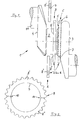
- a one-piece, multi-cranked crankshaft 1 points to one of two via a main bearing journal 2 connected crank webs 3, 4 arranged on the pin side Recording 5 for a rotating with the crankshaft 1 or rotating body 6.
- Recording 5 is designed as a centering collar 7 for one shown in more detail in FIG Sprocket 8 as body 6.
- the sprocket preferably made from a case hardening steel 8 includes a center hole 9, the diameter compared to that of the centering collar 7 by a predetermined one Dimension is chosen smaller.
- a center hole 9 axially extending, diametrically arranged Notches 10 provided in the case hardened sprocket 8 an initiation of break separation into halves Parts 8 ', 8 "are used.
- the one-piece sprocket 8 is preferably in Area of the center hole 9 is heated up and then moved to position C.
- the sprocket 8 will by means of a shrink fit on the centering collar 7 with the crank arm 3 or the crankshaft 1 rotatably connected.
- a counterweight may be provided.
Landscapes
- Engineering & Computer Science (AREA)
- General Engineering & Computer Science (AREA)
- Mechanical Engineering (AREA)
- Ocean & Marine Engineering (AREA)
- Shafts, Cranks, Connecting Bars, And Related Bearings (AREA)
- Gears, Cams (AREA)
Description
- Figur 1
- abschnittsweise eine Kurbelwelle mit einem zu einem Hauptlagerzapfen koaxialen Zentrierbund an einer Wange zur Anordnung eines Kettenrades,
- Figur 2
- das Kettenrad in Stirnansicht vor dem Bruchtrennen in hälftige Teile.
Claims (4)
- Montageverfahren für einen insbesondere eine Verzahnung tragenden Körper an einer einteilig gefertigten, mehrfach gekröpften Kurbelwelle einer Hubkolbenmaschine, vor allem Brennkraftmaschine,dadurch gekennzeichnet,wobei die Kurbelwelle (1) an einer von zwei über einen Lagerzapfen (2) verbundenen Kurbelwangen (3, 4) eine lagerzapfenseitig angeordnete Aufnahme (5 bzw. 7) aufweist zur Montage des mit der Kurbelwange (3) drehfest verbindbaren Körpers (6 bzw. 8), wobei die Aufnahme einen größeren Durchmesser als der Lagerzapfen aufweist,daß der eine der Aufnahme (5 bzw. 7) zugeordnete Durchbrechung (9) aufweisende Körper (6 bzw. 8) mittels Bruchtrennen zumindest in zwei Teile (8', 8'') geteilt wird,daß diese beiden Teile (8', 8'') im Bereich des der Aufnahme (5 bzw. 7) benachbarten Lagerzapfens (2) zu einem diesen umschließenden Körper (6 bzw. 8) vereinigt und miteinander fest verbunden werden,und dann der einteilige Körper (6 bzw. 8) verschoben und mittels der Aufnahme (5 bzw. 7) zentriert mit der Kurbelwange (3) drehfest verbunden wird.
- Verfahren nach Anspruch 1, dadurch gekennzeichnet,daß der Körper (6) als ein im wesentlichen scheibenförmiges, gezahntes Rad (Kettenrad 8) mit einer im Durchmesser gegenüber dem der Aufnahme (5 bzw. Zentrierbund 7) kleineren Bohrung (9) gefertigt und im weiteren bruchgetrennt wird,daß die beiden Zahnradteile (8', 8'') durch Schweißen miteinander fest verbunden werden, unddaß dann das wieder einteilige Zahnrad (8) mittels Press- oder Schrumpfsitz auf dem Zentrierbund (7) drehfest mit der Kurbelwange (3) bzw. der Kurbelwelle (1) verbunden wird.
- Verfahren nach Anspruch 1 und 2, dadurch gekennzeichnet,daß das Zahnrad (Kettenrad 8) aus einem Einsatzstahl gefertigt und vor dem Bruchtrennen einsatzgehärtet wird, unddaß die Teile (8', 8'') des bruchgetrennten Zahnrades (8) durch Laser- oder Elektronenstrahl-Schweißen miteinander fest verbunden werden.
- Verfahren nach Anspruch 1 und 2, dadurch gekennzeichnet, daß das Zahnrad (Kettenrad 8) als Sinterteil aus einem ggf. legierten Stahlpulver gefertigt wird.
Applications Claiming Priority (2)
| Application Number | Priority Date | Filing Date | Title |
|---|---|---|---|
| DE4415100A DE4415100A1 (de) | 1994-04-29 | 1994-04-29 | Montageverfahren für einen insbesondere eine Verzahnung tragenden Körper an einer einteilig gefertigten, mehrfach gekröpften Kurbelwelle einer Hubkolbenmaschine, vor allem Brennkraftmaschine |
| DE4415100 | 1994-04-29 |
Publications (3)
| Publication Number | Publication Date |
|---|---|
| EP0684397A2 EP0684397A2 (de) | 1995-11-29 |
| EP0684397A3 EP0684397A3 (de) | 1996-10-23 |
| EP0684397B1 true EP0684397B1 (de) | 1999-06-16 |
Family
ID=6516848
Family Applications (1)
| Application Number | Title | Priority Date | Filing Date |
|---|---|---|---|
| EP95101013A Expired - Lifetime EP0684397B1 (de) | 1994-04-29 | 1995-01-26 | Montageverfahren für einen insbesondere eine Verzahnung tragenden Körper an einer einteilig gefertigten, mehrfach gekröpften Kubelwelle einer Hubkolbenmaschine, vor allem Brennkraftmaschine |
Country Status (3)
| Country | Link |
|---|---|
| EP (1) | EP0684397B1 (de) |
| DE (2) | DE4415100A1 (de) |
| ES (1) | ES2133594T3 (de) |
Families Citing this family (8)
| Publication number | Priority date | Publication date | Assignee | Title |
|---|---|---|---|---|
| GB2346670B (en) * | 1999-02-11 | 2003-07-16 | United Eng Forgings Ltd | Crankshaft construction |
| EP1624204A1 (de) * | 2004-08-05 | 2006-02-08 | Ford Global Technologies, LLC, A subsidary of Ford Motor Company | Welle mit daran befestigtem Übertragungselement |
| DE102008030897B3 (de) * | 2008-06-30 | 2009-08-13 | Ford Global Technologies, LLC, Dearborn | Montageverfahren für ein Lager an einer Welle |
| DE102008046167B4 (de) | 2008-09-06 | 2019-08-29 | Bayerische Motoren Werke Aktiengesellschaft | Montageverfahren für ein geteiltes Kettenrad an einer Kurbelwelle |
| DE102014216460B4 (de) * | 2014-08-19 | 2022-02-24 | Bayerische Motoren Werke Aktiengesellschaft | Stirnzahnrad |
| FR3036146B1 (fr) * | 2015-05-11 | 2017-05-26 | Peugeot Citroen Automobiles Sa | Piece excentrique pour systeme de variation du taux de compression d'un moteur thermique |
| CN105972054A (zh) * | 2016-06-24 | 2016-09-28 | 珠海凌达压缩机有限公司 | 压缩机曲轴和压缩机 |
| FI128312B (fi) * | 2018-04-27 | 2020-03-13 | Andritz Oy | Voimansiirtopyörä ja menetelmä sen asentamiseksi |
Family Cites Families (12)
| Publication number | Priority date | Publication date | Assignee | Title |
|---|---|---|---|---|
| DD55487A (de) * | ||||
| DE729777C (de) * | 1938-11-01 | 1942-12-23 | Bmw Flugmotorenbau Ges M B H | Durch Verformung eines Rohrkoerpers hergestellte Kurbelwelle, insbesondere fuer Flugmotoren |
| US3546762A (en) * | 1968-07-01 | 1970-12-15 | Textron Inc | Method of making an antifriction bearing |
| DE1951097A1 (de) * | 1969-10-10 | 1971-04-22 | Porsche Kg | Zusammengesetzte Kurbelwelle mit einem Antriebszahnrad,fuer mehrzylindrige Kolbenmaschinen,insbesondere Brennkraftmaschinen |
| DE2935384A1 (de) * | 1979-09-01 | 1981-03-19 | Daimler-Benz Ag, 7000 Stuttgart | Brennkraftmaschine mit einem massenausgleich zweiter ordnung |
| DE3138632A1 (de) * | 1981-09-29 | 1983-04-14 | FAG Kugelfischer Georg Schäfer & Co, 8720 Schweinfurt | Verfahren zum brechen von ringen, insbesondere waelzlagerringen |
| US5265566A (en) * | 1991-12-23 | 1993-11-30 | General Motors Corporation | Assembled seal disc for a crankshaft |
| DE4232432A1 (de) * | 1992-09-28 | 1994-03-31 | Krebsoege Gmbh Sintermetall | Pulvermetallurgisches Pleuel und Verfahren zu seiner Herstellung |
| DE4307561A1 (de) * | 1993-03-10 | 1994-09-15 | Bayerische Motoren Werke Ag | Lagerung einer Welle in einem Maschinengehäuse, insbesondere Kurbelwelle im Triebwerksgehäuse einer Brennkraftmaschine |
| DE4311108C1 (de) * | 1993-04-05 | 1994-04-07 | Schulte Kg Hammerwerk | Aus Stahl geschmiedetes Pleuel |
| DE9305170U1 (de) * | 1993-04-05 | 1993-07-08 | Hammerwerk Schulte GmbH & Co. KG, 5970 Plettenberg | Aus Stahl geschmiedetes Pleuel |
| DE9317323U1 (de) * | 1993-11-16 | 1994-01-13 | Brockhaus Söhne GmbH & Co KG, 58840 Plettenberg | Pleuelstange aus Stahl mit beim Schmieden erzeugter Sollbruchstelle für das Bruchtrennen |
-
1994
- 1994-04-29 DE DE4415100A patent/DE4415100A1/de not_active Withdrawn
-
1995
- 1995-01-26 DE DE59506200T patent/DE59506200D1/de not_active Expired - Lifetime
- 1995-01-26 ES ES95101013T patent/ES2133594T3/es not_active Expired - Lifetime
- 1995-01-26 EP EP95101013A patent/EP0684397B1/de not_active Expired - Lifetime
Also Published As
| Publication number | Publication date |
|---|---|
| ES2133594T3 (es) | 1999-09-16 |
| DE4415100A1 (de) | 1995-11-02 |
| EP0684397A3 (de) | 1996-10-23 |
| EP0684397A2 (de) | 1995-11-29 |
| DE59506200D1 (de) | 1999-07-22 |
Similar Documents
| Publication | Publication Date | Title |
|---|---|---|
| DE3641201C2 (de) | ||
| EP2418055A2 (de) | Handgeführtes Arbeitsgerät | |
| DE3001782A1 (de) | Zahnrad | |
| DE4013298A1 (de) | Befestigung eines schwungrades an der kurbelwelle einer brennkraftmaschine | |
| EP0684397B1 (de) | Montageverfahren für einen insbesondere eine Verzahnung tragenden Körper an einer einteilig gefertigten, mehrfach gekröpften Kubelwelle einer Hubkolbenmaschine, vor allem Brennkraftmaschine | |
| DE3530244C2 (de) | ||
| DE4139411C2 (de) | Tragbares Arbeitsgerät, insbesondere Rasenmäher | |
| DE102011012941A1 (de) | Nockenwelle mit Gewichtsverringerungsmerkmalen und Herstellungsverfahren | |
| DE102013003165A1 (de) | Adaptersystem, Getriebemotor, Getriebemotorbaureihe und Herstellverfahren für einen Getriebemotor | |
| DE3942761A1 (de) | Kettenzahnrad eines kettentriebes mit daempfungsmitteln | |
| DE19540391A1 (de) | Bohr- und Meisselgerät | |
| DE19902920A1 (de) | Hubkolben-Brennkraftmaschine | |
| DE102004002847A1 (de) | KFZ-Zahnradanordnung für ein KFZ-Hilfsgetriebe sowie Flansch und Verfahren zum Herstellen einer solchen KFZ-Zahnradanordnung | |
| DE4412476A1 (de) | Ausgleichswelle | |
| DE102019203340A1 (de) | Differential- oder Verteilergetriebe | |
| DE3025600A1 (de) | Schwungrad | |
| EP1024276A2 (de) | Hubkolben-Brennkraftmaschine | |
| DE19607077C2 (de) | Kraftfahrzeug-Differential | |
| DE19912130B4 (de) | Gebaute Schiebemuffe einer Synchronisiereinheit für Schaltgetriebe | |
| DE3506928C2 (de) | Innenzahnradpumpe als Schmierölpumpe für einen Verbrennungsmotor | |
| WO1982002419A1 (en) | Starter for combustion engine | |
| DE69409888T2 (de) | Auswuchtmechanismus für eine Brennkraftmaschine | |
| EP0947670B1 (de) | Nockenwellentrieb einer Brennkraftmaschine | |
| DE102010032530A1 (de) | Anordnung eines Ausgleichsgewichts an einer Ausgleichswelle | |
| EP0939249B1 (de) | Zahnstange für einen Zahnstangenantrieb |
Legal Events
| Date | Code | Title | Description |
|---|---|---|---|
| PUAI | Public reference made under article 153(3) epc to a published international application that has entered the european phase |
Free format text: ORIGINAL CODE: 0009012 |
|
| AK | Designated contracting states |
Kind code of ref document: A2 Designated state(s): DE ES FR GB IT |
|
| PUAL | Search report despatched |
Free format text: ORIGINAL CODE: 0009013 |
|
| AK | Designated contracting states |
Kind code of ref document: A3 Designated state(s): DE ES FR GB IT |
|
| 17P | Request for examination filed |
Effective date: 19961113 |
|
| GRAG | Despatch of communication of intention to grant |
Free format text: ORIGINAL CODE: EPIDOS AGRA |
|
| 17Q | First examination report despatched |
Effective date: 19980904 |
|
| GRAG | Despatch of communication of intention to grant |
Free format text: ORIGINAL CODE: EPIDOS AGRA |
|
| GRAH | Despatch of communication of intention to grant a patent |
Free format text: ORIGINAL CODE: EPIDOS IGRA |
|
| GRAH | Despatch of communication of intention to grant a patent |
Free format text: ORIGINAL CODE: EPIDOS IGRA |
|
| GRAA | (expected) grant |
Free format text: ORIGINAL CODE: 0009210 |
|
| AK | Designated contracting states |
Kind code of ref document: B1 Designated state(s): DE ES FR GB IT |
|
| GBT | Gb: translation of ep patent filed (gb section 77(6)(a)/1977) |
Effective date: 19990618 |
|
| REF | Corresponds to: |
Ref document number: 59506200 Country of ref document: DE Date of ref document: 19990722 |
|
| ET | Fr: translation filed | ||
| ITF | It: translation for a ep patent filed | ||
| REG | Reference to a national code |
Ref country code: ES Ref legal event code: FG2A Ref document number: 2133594 Country of ref document: ES Kind code of ref document: T3 |
|
| PLBE | No opposition filed within time limit |
Free format text: ORIGINAL CODE: 0009261 |
|
| STAA | Information on the status of an ep patent application or granted ep patent |
Free format text: STATUS: NO OPPOSITION FILED WITHIN TIME LIMIT |
|
| 26N | No opposition filed | ||
| REG | Reference to a national code |
Ref country code: GB Ref legal event code: IF02 |
|
| PGFP | Annual fee paid to national office [announced via postgrant information from national office to epo] |
Ref country code: ES Payment date: 20111221 Year of fee payment: 18 |
|
| PGFP | Annual fee paid to national office [announced via postgrant information from national office to epo] |
Ref country code: FR Payment date: 20120214 Year of fee payment: 18 |
|
| PGFP | Annual fee paid to national office [announced via postgrant information from national office to epo] |
Ref country code: DE Payment date: 20120215 Year of fee payment: 18 |
|
| PGFP | Annual fee paid to national office [announced via postgrant information from national office to epo] |
Ref country code: IT Payment date: 20120126 Year of fee payment: 18 Ref country code: GB Payment date: 20120125 Year of fee payment: 18 |
|
| GBPC | Gb: european patent ceased through non-payment of renewal fee |
Effective date: 20130126 |
|
| REG | Reference to a national code |
Ref country code: FR Ref legal event code: ST Effective date: 20130930 |
|
| PG25 | Lapsed in a contracting state [announced via postgrant information from national office to epo] |
Ref country code: DE Free format text: LAPSE BECAUSE OF NON-PAYMENT OF DUE FEES Effective date: 20130801 |
|
| REG | Reference to a national code |
Ref country code: DE Ref legal event code: R119 Ref document number: 59506200 Country of ref document: DE Effective date: 20130801 |
|
| PG25 | Lapsed in a contracting state [announced via postgrant information from national office to epo] |
Ref country code: FR Free format text: LAPSE BECAUSE OF NON-PAYMENT OF DUE FEES Effective date: 20130131 Ref country code: GB Free format text: LAPSE BECAUSE OF NON-PAYMENT OF DUE FEES Effective date: 20130126 |
|
| PG25 | Lapsed in a contracting state [announced via postgrant information from national office to epo] |
Ref country code: IT Free format text: LAPSE BECAUSE OF NON-PAYMENT OF DUE FEES Effective date: 20130126 |
|
| REG | Reference to a national code |
Ref country code: ES Ref legal event code: FD2A Effective date: 20140324 |
|
| PG25 | Lapsed in a contracting state [announced via postgrant information from national office to epo] |
Ref country code: ES Free format text: LAPSE BECAUSE OF NON-PAYMENT OF DUE FEES Effective date: 20130127 |