EP0684397B1 - Method of mounting an element, especially a toothed element on a one-piece crankshaft with multiple cranks of a reciprocating piston engine, especially an internal combustion engine - Google Patents
Method of mounting an element, especially a toothed element on a one-piece crankshaft with multiple cranks of a reciprocating piston engine, especially an internal combustion engine Download PDFInfo
- Publication number
- EP0684397B1 EP0684397B1 EP95101013A EP95101013A EP0684397B1 EP 0684397 B1 EP0684397 B1 EP 0684397B1 EP 95101013 A EP95101013 A EP 95101013A EP 95101013 A EP95101013 A EP 95101013A EP 0684397 B1 EP0684397 B1 EP 0684397B1
- Authority
- EP
- European Patent Office
- Prior art keywords
- holder
- crankshaft
- toothed wheel
- parts
- fracture
- Prior art date
- Legal status (The legal status is an assumption and is not a legal conclusion. Google has not performed a legal analysis and makes no representation as to the accuracy of the status listed.)
- Expired - Lifetime
Links
- 238000000034 method Methods 0.000 title claims description 8
- 238000002485 combustion reaction Methods 0.000 title claims description 3
- 238000003466 welding Methods 0.000 claims description 7
- 238000000926 separation method Methods 0.000 claims description 6
- 229910000831 Steel Inorganic materials 0.000 claims description 4
- 239000010959 steel Substances 0.000 claims description 4
- 238000010894 electron beam technology Methods 0.000 claims description 2
- 239000000843 powder Substances 0.000 claims 1
- 230000000977 initiatory effect Effects 0.000 description 1
Images
Classifications
-
- B—PERFORMING OPERATIONS; TRANSPORTING
- B23—MACHINE TOOLS; METAL-WORKING NOT OTHERWISE PROVIDED FOR
- B23D—PLANING; SLOTTING; SHEARING; BROACHING; SAWING; FILING; SCRAPING; LIKE OPERATIONS FOR WORKING METAL BY REMOVING MATERIAL, NOT OTHERWISE PROVIDED FOR
- B23D31/00—Shearing machines or shearing devices covered by none or more than one of the groups B23D15/00 - B23D29/00; Combinations of shearing machines
- B23D31/002—Breaking machines, i.e. pre-cutting and subsequent breaking
- B23D31/003—Breaking machines, i.e. pre-cutting and subsequent breaking for rings
-
- B—PERFORMING OPERATIONS; TRANSPORTING
- B23—MACHINE TOOLS; METAL-WORKING NOT OTHERWISE PROVIDED FOR
- B23P—METAL-WORKING NOT OTHERWISE PROVIDED FOR; COMBINED OPERATIONS; UNIVERSAL MACHINE TOOLS
- B23P11/00—Connecting or disconnecting metal parts or objects by metal-working techniques not otherwise provided for
- B23P11/02—Connecting or disconnecting metal parts or objects by metal-working techniques not otherwise provided for by first expanding and then shrinking or vice versa, e.g. by using pressure fluids; by making force fits
- B23P11/025—Connecting or disconnecting metal parts or objects by metal-working techniques not otherwise provided for by first expanding and then shrinking or vice versa, e.g. by using pressure fluids; by making force fits by using heat or cold
-
- B—PERFORMING OPERATIONS; TRANSPORTING
- B23—MACHINE TOOLS; METAL-WORKING NOT OTHERWISE PROVIDED FOR
- B23P—METAL-WORKING NOT OTHERWISE PROVIDED FOR; COMBINED OPERATIONS; UNIVERSAL MACHINE TOOLS
- B23P19/00—Machines for simply fitting together or separating metal parts or objects, or metal and non-metal parts, whether or not involving some deformation; Tools or devices therefor so far as not provided for in other classes
- B23P19/04—Machines for simply fitting together or separating metal parts or objects, or metal and non-metal parts, whether or not involving some deformation; Tools or devices therefor so far as not provided for in other classes for assembling or disassembling parts
-
- F—MECHANICAL ENGINEERING; LIGHTING; HEATING; WEAPONS; BLASTING
- F16—ENGINEERING ELEMENTS AND UNITS; GENERAL MEASURES FOR PRODUCING AND MAINTAINING EFFECTIVE FUNCTIONING OF MACHINES OR INSTALLATIONS; THERMAL INSULATION IN GENERAL
- F16C—SHAFTS; FLEXIBLE SHAFTS; ELEMENTS OR CRANKSHAFT MECHANISMS; ROTARY BODIES OTHER THAN GEARING ELEMENTS; BEARINGS
- F16C3/00—Shafts; Axles; Cranks; Eccentrics
- F16C3/04—Crankshafts, eccentric-shafts; Cranks, eccentrics
- F16C3/06—Crankshafts
-
- F—MECHANICAL ENGINEERING; LIGHTING; HEATING; WEAPONS; BLASTING
- F16—ENGINEERING ELEMENTS AND UNITS; GENERAL MEASURES FOR PRODUCING AND MAINTAINING EFFECTIVE FUNCTIONING OF MACHINES OR INSTALLATIONS; THERMAL INSULATION IN GENERAL
- F16D—COUPLINGS FOR TRANSMITTING ROTATION; CLUTCHES; BRAKES
- F16D1/00—Couplings for rigidly connecting two coaxial shafts or other movable machine elements
- F16D1/06—Couplings for rigidly connecting two coaxial shafts or other movable machine elements for attachment of a member on a shaft or on a shaft-end
- F16D1/064—Couplings for rigidly connecting two coaxial shafts or other movable machine elements for attachment of a member on a shaft or on a shaft-end non-disconnectable
- F16D1/068—Couplings for rigidly connecting two coaxial shafts or other movable machine elements for attachment of a member on a shaft or on a shaft-end non-disconnectable involving gluing, welding or the like
-
- F—MECHANICAL ENGINEERING; LIGHTING; HEATING; WEAPONS; BLASTING
- F16—ENGINEERING ELEMENTS AND UNITS; GENERAL MEASURES FOR PRODUCING AND MAINTAINING EFFECTIVE FUNCTIONING OF MACHINES OR INSTALLATIONS; THERMAL INSULATION IN GENERAL
- F16H—GEARING
- F16H55/00—Elements with teeth or friction surfaces for conveying motion; Worms, pulleys or sheaves for gearing mechanisms
- F16H55/02—Toothed members; Worms
- F16H55/12—Toothed members; Worms with body or rim assembled out of detachable parts
-
- B—PERFORMING OPERATIONS; TRANSPORTING
- B23—MACHINE TOOLS; METAL-WORKING NOT OTHERWISE PROVIDED FOR
- B23P—METAL-WORKING NOT OTHERWISE PROVIDED FOR; COMBINED OPERATIONS; UNIVERSAL MACHINE TOOLS
- B23P2700/00—Indexing scheme relating to the articles being treated, e.g. manufactured, repaired, assembled, connected or other operations covered in the subgroups
- B23P2700/07—Crankshafts
Definitions
- the invention is based on the preamble of the claim 1 from DE-A 29 35 384.
- This document shows and describes a one-piece, multi-cranked crankshaft of an internal combustion engine centered on a crank arm with one arranged and fastened toothed ring for a chain drive.
- the diameter of the center hole of the gear ring is chosen so large that the toothed ring at least from a crankshaft end over all pins and these connecting crank webs can be pushed to Arrangement on the predetermined crank arm.
- Balance weights required in this section of the crankshaft detachable with a respective crank cheek connected.
- a disadvantage of this type of mounting of the toothed ring or Gear is that its smallest inside diameter and thus also the smallest pitch circle diameter essentially by the dimensions of the connecting the crankshaft pins Cheek sections is determined.
- the invention has for its object the assembly method for a separate one from the crankshaft to improve the crankshaft arrangeable body so that at least its dimensions relevant to the arrangement essentially independent of the dimensions of the crankshaft are selectable.
- the assembly method according to the invention is in an embodiment of the invention according to further claims 2 and 4 for toothed wheels - sprockets; Gears; Encoder or Pulse wheels - preferably used.
- the half gear parts in the area adjacent to the centering collar Main bearing journal by welding, preferably laser or electron beam welding, firmly connected.
- the one-piece gear on this is by means of Press fit or a temperature-related shrink fit the centering collar rotatably with the crank arm or the Crankshaft connected.
- Laser welding are the gears made of case hardening steel be case hardened before breaking. Can continue the gear / chain wheels are also designed as sintered parts be.
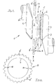
- a one-piece, multi-cranked crankshaft 1 points to one of two via a main bearing journal 2 connected crank webs 3, 4 arranged on the pin side Recording 5 for a rotating with the crankshaft 1 or rotating body 6.
- Recording 5 is designed as a centering collar 7 for one shown in more detail in FIG Sprocket 8 as body 6.
- the sprocket preferably made from a case hardening steel 8 includes a center hole 9, the diameter compared to that of the centering collar 7 by a predetermined one Dimension is chosen smaller.
- a center hole 9 axially extending, diametrically arranged Notches 10 provided in the case hardened sprocket 8 an initiation of break separation into halves Parts 8 ', 8 "are used.
- the one-piece sprocket 8 is preferably in Area of the center hole 9 is heated up and then moved to position C.
- the sprocket 8 will by means of a shrink fit on the centering collar 7 with the crank arm 3 or the crankshaft 1 rotatably connected.
- a counterweight may be provided.
Landscapes
- Engineering & Computer Science (AREA)
- General Engineering & Computer Science (AREA)
- Mechanical Engineering (AREA)
- Ocean & Marine Engineering (AREA)
- Shafts, Cranks, Connecting Bars, And Related Bearings (AREA)
- Gears, Cams (AREA)
Description
Die Erfindung geht gemäß dem Oberbegriff des Patentanspruches 1 von der DE-A 29 35 384 aus.The invention is based on the preamble of the claim 1 from DE-A 29 35 384.
Dieses Dokument zeigt und beschreibt eine einteilig gefertigte, mehrfach gekröpfte Kurbelwelle einer Brennkraftmaschine mit einem an einer Kurbelwange zentriert angeordneten und befestigten Zahnring für einen Kettentrieb. Der Durchmesser der Zentrierbohrung des Zahnringes ist hierbei so groß gewählt, daß der Zahnring zumindest von einem Kurbelwellenende her über sämtliche Zapfen und diese verbindenden Kurbelwangen geschoben werden kann zur Anordnung an der vorbestimmten Kurbelwange. Um den Zahnring über bestimmte Kurbelwangen schieben zu können, sind in diesem Abschnitt der Kurbelwelle erforderliche Ausgleichsgewichte mit einer jeweiligen Kurbelwange lösbar verbunden.This document shows and describes a one-piece, multi-cranked crankshaft of an internal combustion engine centered on a crank arm with one arranged and fastened toothed ring for a chain drive. The diameter of the center hole of the gear ring is chosen so large that the toothed ring at least from a crankshaft end over all pins and these connecting crank webs can be pushed to Arrangement on the predetermined crank arm. To the gear ring to be able to push over certain crank webs Balance weights required in this section of the crankshaft detachable with a respective crank cheek connected.
Nachteilig bei dieser Art der Montage des Zahnringes bzw. Zahnrades ist, daß dessen kleinster Innendurchmesser und damit auch kleinster Teilkreisdurchmesser im wesentlichen durch die Abmessungen der die Zapfen der Kurbelwelle verbindenden Wangenabschnitte bestimmt ist.A disadvantage of this type of mounting of the toothed ring or Gear is that its smallest inside diameter and thus also the smallest pitch circle diameter essentially by the dimensions of the connecting the crankshaft pins Cheek sections is determined.
Der Erfindung liegt die Aufgabe zugrunde, das Montageverfahren für einen von der Kurbelwelle gesonderten, an der Kurbelwelle anordbaren Körper so zu verbessern, daß zumindest dessen für die Anordnung relevante Abmessungen im wesentlichen unabhängig von den Abmessungen der Kurbelwelle wählbar sind.The invention has for its object the assembly method for a separate one from the crankshaft to improve the crankshaft arrangeable body so that at least its dimensions relevant to the arrangement essentially independent of the dimensions of the crankshaft are selectable.
Diese Aufgabe wird gemäß dem Patentanspruch 1 gelöst, wobei der eine der Aufnahme zugeordnete Durchbrechung aufweisende Körper mittels Bruchtrennen zumindest in zwei Teile geteilt wird, und diese beiden Teile im Bereich des der Aufnahme benachbarten Lagerzapfens zu einem diesen umschließenden Körper vereinigt und miteinander fest verbunden werden, und dann der einteilige Körper verschoben und mittels der Aufnahme zentriert mit der Kurbelwange drehfest verbunden wird.This object is achieved according to claim 1, wherein the one having an opening associated with the receptacle Bodies by means of fracture separation at least in two Parts is shared, and these two parts in the area of the inclusion of adjacent trunnions to one unites this enclosing body and with each other be firmly connected, and then the one-piece body moved and rotatably centered by means of the holder with the crank arm is connected.
Mit dem erfindungsgemäßen Teilen des mit der Kurbelwelle umlaufenden bzw. mitdrehenden Körpers in seinem für die Kurbelwelle vorgesehenen Verbindungsbereich mittels des bekannten, spanlosen Bruchtrennens lassen sich die Abmessungen des Körpers vorteilhaft frei wählen, wobei mit dem Bruchtrennen weitere Nacharbeiten vorteilhaft vermieden sind.With the parts of the invention with the crankshaft revolving or rotating body in his for the Crankshaft provided connection area by means of known, non-cutting breaking separation, the dimensions of the body advantageously freely choose, with the break separation advantageously avoided further reworking are.
Das erfindungsgemäße Montageverfahren wird in Ausgestaltung
der Erfindung gemäß den weiteren Ansprüchen 2 und 4
für gezahnte Räder - Kettenräder; Zahnräder; Geber- oder
Impulsräder - bevorzugt verwendet. Hierbei wird ein im
wesentlichen scheibenförmiges, gezahntes Rad mit einer im
Durchmesser gegenüber dem der Aufnahme - z.B. einem Zentrierbund
- kleineren Bohrung gefertigt und im weiteren
bruchgetrennt. Anschließend werden die hälftigen Zahnradteile
im Bereich des dem Zentrierbund benachbarten
Haupt-Lagerzapfens durch Schweißen, vorzugsweise Laser-
oder Elektronenstrahlschweißen, miteinander fest verbunden.
Das hierauf wieder einteilige Zahnrad wird mittels
Pressitz oder einem temperaturbedingten Schrumpfsitz auf
dem Zentrierbund drehfest mit der Kurbelwange bzw. der
Kurbelwelle verbunden. Vorteilhaft im Hinblick auf das
Laserschweißen sind die Zahnräder aus Einsatzstahl, die
vor dem Bruchtrennen einsatzgehärtet werden. Weiter können
die Zahn-/Kettenräder auch als Sinterteile ausgebildet
sein.The assembly method according to the invention is in an embodiment
of the invention according to
Das erfindungsgemäße Verfahren ist anhand einer in der Zeichnung beispielhaft verdeutlichten Montage eines Kettenrades an der Wange einer Kurbelwelle beschrieben. Es zeigt
- Figur 1
- abschnittsweise eine Kurbelwelle mit einem zu einem Hauptlagerzapfen koaxialen Zentrierbund an einer Wange zur Anordnung eines Kettenrades,
Figur 2- das Kettenrad in Stirnansicht vor dem Bruchtrennen in hälftige Teile.
- Figure 1
- sections of a crankshaft with a centering collar coaxial to a main bearing journal on a cheek for arranging a chain wheel,
- Figure 2
- the sprocket in front view before breaking into halves.
Eine einteilig gefertigte, mehrfach gekröpfte Kurbelwelle
1 weist an einer von zwei über einen Hauptlagerzapfen 2
verbundenen Kurbelwangen 3, 4 eine zapfenseitig angeordnete
Aufnahme 5 für einen mit der Kurbelwelle 1 umlaufenden
bzw. mitdrehenden Körper 6 auf. Die Aufnahme 5 ist
als Zentrierbund 7 gestaltet für ein in Figur 2 näher gezeigtes
Kettenrad 8 als Körper 6.A one-piece, multi-cranked crankshaft
1 points to one of two via a main bearing
Das vorzugsweise aus einem Einsatzstahl gefertigte Kettenrad
8 umfaßt eine Zentrierbohrung 9, die im Durchmesser
gegenüber dem des Zentrierbundes 7 um ein vorbestimmtes
Maß kleiner gewählt ist. Weiter sind in der Zentrierbohrung
9 axial verlaufende, diametral angeordnete
Kerben 10 vorgesehen, die in dem einsatzgehärteten Kettenrad
8 einer Einleitung der Bruchtrennung in hälftige
Teile 8', 8" dienen. Zur Sicherstellung einer entweder
in den Zahngründen oder in den Zahnköpfen außerhalb der
tragenden Zahnflanken endenden Bruchtrennung kann das
Kettenrad 8 zusätzlich zumindest an einer Stirnseite geschwächt
sein.The sprocket, preferably made from a
Nachdem das einsatzgehärtete Kettenrad 8 in die hälftigen
Teile 8', 8" gebrochen ist - Position A -, werden diese
beiden Teile 8', 8" im Bereich des dem Zentrierbund 7
benachbarten Hauptlagerzapfens 2 zu einem diesen umschließenden
Körper 6 vereinigt - Position B - und durch
Schweißen, insbesondere durch Laserschweißen, fest miteinander
verbunden.After the case hardened
Das wiederum einteilige Kettenrad 8 wird vorzugsweise im
Bereich der Zentrierbohrung 9 stark erwärmt und anschließend
in Position C verschoben. Das Kettenrad 8 wird
mittels Schrumpfsitz auf dem Zentrierbund 7 mit der Kurbelwange
3 bzw. der Kurbelwelle 1 drehfest verbunden.The one-
Als Körper 6 kann neben jeder Art von Zahnrad z.B. auch
ein Ausgleichsgewicht vorgesehen sein. Weiter kann jeder
vorgenannte Körper ein Sinter- oder Gußteil sein.As the
Claims (4)
- A method of fitting a body, especially toothed, on a one-part multi-throw crankshaft of a reciprocating engine, especially an internal combustion engine,characterised in thatwherein the crankshaft (1) has a holder (5 or 7) on one out of two crank webs (3, 4) connected via a journal pin (2), and disposed on the same side as the pin, for fitting the body (6 or 8) so as to be connected to and rotating integrally with the crank web (3), wherein the holder has a greater diameter than the journal pin,the body (6 or 8), which has an aperture (9) associated with the holder (5 or 7), is divided by fracture into at least two parts (8', 8"),the two parts (8', 8"), in the region of the journal pin (2) adjoining the holder (5 or 7), are joined to form a body (6 or 8) surrounding the pin and are firmly connected to one another,after which the single-part body (6 or 8) is slid and sintered by the holder (5 or 7) and joined to the crank web (3) so as to rotate integrally therewith.
- A method according to claim 1, characterised in thatthe body (6) is produced in the form of a substantially disc-shaped toothed wheel (chain wheel 8) with a bore (9) having a diameter smaller than that of the holder (5 or centring collar 7) and is then separated by fracture,the two parts (8', 8") of the toothed wheel are firmly joined together by welding, andthe toothed wheel (8), now again in one piece, is connected by a force or shrink fit on the centring collar (9) so as to rotate integrally with the crank web (3) or crankshaft (1).
- A method according to claims 1 and 2, characterised in thatthe toothed wheel (chain wheel 8) is made of case-hardening steel and is case-hardened before separation by fracture, andthe parts (8', 8") of the toothed wheel (8) separated by fracture are firmly joined together by laser or electron-beam welding.
- A method according to claims 1 and 2, characterised in that the toothed wheel (chain wheel 8) is made in the form of a sintered part from steel powder, optionally alloyed.
Applications Claiming Priority (2)
| Application Number | Priority Date | Filing Date | Title |
|---|---|---|---|
| DE4415100 | 1994-04-29 | ||
| DE4415100A DE4415100A1 (en) | 1994-04-29 | 1994-04-29 | Assembly method for a body, in particular a toothing, on a one-piece, multi-cranked crankshaft of a reciprocating piston engine, especially an internal combustion engine |
Publications (3)
| Publication Number | Publication Date |
|---|---|
| EP0684397A2 EP0684397A2 (en) | 1995-11-29 |
| EP0684397A3 EP0684397A3 (en) | 1996-10-23 |
| EP0684397B1 true EP0684397B1 (en) | 1999-06-16 |
Family
ID=6516848
Family Applications (1)
| Application Number | Title | Priority Date | Filing Date |
|---|---|---|---|
| EP95101013A Expired - Lifetime EP0684397B1 (en) | 1994-04-29 | 1995-01-26 | Method of mounting an element, especially a toothed element on a one-piece crankshaft with multiple cranks of a reciprocating piston engine, especially an internal combustion engine |
Country Status (3)
| Country | Link |
|---|---|
| EP (1) | EP0684397B1 (en) |
| DE (2) | DE4415100A1 (en) |
| ES (1) | ES2133594T3 (en) |
Families Citing this family (8)
| Publication number | Priority date | Publication date | Assignee | Title |
|---|---|---|---|---|
| GB2346670B (en) * | 1999-02-11 | 2003-07-16 | United Eng Forgings Ltd | Crankshaft construction |
| EP1624204A1 (en) * | 2004-08-05 | 2006-02-08 | Ford Global Technologies, LLC, A subsidary of Ford Motor Company | Shaft having a transmission element attached to it |
| DE102008030897B3 (en) * | 2008-06-30 | 2009-08-13 | Ford Global Technologies, LLC, Dearborn | Bearing e.g. connecting rod bearing, mounting method for reciprocating piston engine of motor vehicle, involves fixedly connecting bearing housing parts by welding process, where welding of parts is performed in defined external region |
| DE102008046167B4 (en) | 2008-09-06 | 2019-08-29 | Bayerische Motoren Werke Aktiengesellschaft | Assembly procedure for a split sprocket on a crankshaft |
| DE102014216460B4 (en) * | 2014-08-19 | 2022-02-24 | Bayerische Motoren Werke Aktiengesellschaft | spur gear |
| FR3036146B1 (en) * | 2015-05-11 | 2017-05-26 | Peugeot Citroen Automobiles Sa | ECCENTRIC PIECE FOR A COMPRESSION RATE SYSTEM OF A THERMAL ENGINE |
| CN105972054A (en) * | 2016-06-24 | 2016-09-28 | 珠海凌达压缩机有限公司 | compressor crankshaft and compressor |
| FI128312B (en) * | 2018-04-27 | 2020-03-13 | Andritz Oy | Transmission wheel, and method for its mounting |
Family Cites Families (12)
| Publication number | Priority date | Publication date | Assignee | Title |
|---|---|---|---|---|
| DD55487A (en) * | ||||
| DE729777C (en) * | 1938-11-01 | 1942-12-23 | Bmw Flugmotorenbau Ges M B H | Crankshaft produced by deforming a tubular body, especially for aircraft engines |
| US3546762A (en) * | 1968-07-01 | 1970-12-15 | Textron Inc | Method of making an antifriction bearing |
| DE1951097A1 (en) * | 1969-10-10 | 1971-04-22 | Porsche Kg | Composite crankshaft with a drive gear, for multi-cylinder piston engines, especially internal combustion engines |
| DE2935384A1 (en) * | 1979-09-01 | 1981-03-19 | Daimler-Benz Ag, 7000 Stuttgart | Internal combustion engine with a mass balance of second order |
| DE3138632A1 (en) * | 1981-09-29 | 1983-04-14 | FAG Kugelfischer Georg Schäfer & Co, 8720 Schweinfurt | Method for breaking rings, in particular rolling bearing rings |
| US5265566A (en) * | 1991-12-23 | 1993-11-30 | General Motors Corporation | Assembled seal disc for a crankshaft |
| DE4232432A1 (en) * | 1992-09-28 | 1994-03-31 | Krebsoege Gmbh Sintermetall | Powder metallurgy connecting rod - has at least powder metallurgy big-end bearing forming part of compound connecting rod structure |
| DE4307561A1 (en) * | 1993-03-10 | 1994-09-15 | Bayerische Motoren Werke Ag | Mounting of a shaft in a machine housing, especially a crankshaft in the crank case of an internal combustion engine |
| DE4311108C1 (en) * | 1993-04-05 | 1994-04-07 | Schulte Kg Hammerwerk | Connecting rod welded from steel - has break-off point in crank eye, to facilitate cracking |
| DE9305170U1 (en) * | 1993-04-05 | 1993-07-08 | Hammerwerk Schulte GmbH & Co. KG, 5970 Plettenberg | Forged steel connecting rod |
| DE9317323U1 (en) * | 1993-11-16 | 1994-01-13 | Brockhaus Söhne GmbH & Co KG, 58840 Plettenberg | Connecting rod made of steel with a predetermined breaking point for breaking separation created during forging |
-
1994
- 1994-04-29 DE DE4415100A patent/DE4415100A1/en not_active Withdrawn
-
1995
- 1995-01-26 EP EP95101013A patent/EP0684397B1/en not_active Expired - Lifetime
- 1995-01-26 ES ES95101013T patent/ES2133594T3/en not_active Expired - Lifetime
- 1995-01-26 DE DE59506200T patent/DE59506200D1/en not_active Expired - Lifetime
Also Published As
| Publication number | Publication date |
|---|---|
| EP0684397A2 (en) | 1995-11-29 |
| ES2133594T3 (en) | 1999-09-16 |
| EP0684397A3 (en) | 1996-10-23 |
| DE4415100A1 (en) | 1995-11-02 |
| DE59506200D1 (en) | 1999-07-22 |
Similar Documents
| Publication | Publication Date | Title |
|---|---|---|
| DE4013298C2 (en) | Attachment of a flywheel to the crankshaft of an internal combustion engine | |
| DE3641201C2 (en) | ||
| EP2418055A2 (en) | Manually operated work device | |
| DE3001782A1 (en) | GEAR | |
| EP0684397B1 (en) | Method of mounting an element, especially a toothed element on a one-piece crankshaft with multiple cranks of a reciprocating piston engine, especially an internal combustion engine | |
| DE4139411C2 (en) | Portable implement, especially lawn mowers | |
| DE102011012941A1 (en) | Camshaft with weight reduction features and manufacturing process | |
| DE3942761A1 (en) | SPROCKET OF A CHAIN DRIVE WITH DAMPING AGENTS | |
| DE19540391A1 (en) | Drilling and chiseling device | |
| DE19902920A1 (en) | Reciprocating internal combustion engine | |
| DE4412476A1 (en) | Compensating shaft in IC engines | |
| DE102019203340A1 (en) | Differential or transfer case | |
| DE3025600A1 (en) | FLYWHEEL | |
| EP1024276A2 (en) | Internal combustion piston engine | |
| DE19607077C2 (en) | Motor vehicle differential | |
| DE3506928C2 (en) | Internal gear pump as a lubricating oil pump for an internal combustion engine | |
| DE102004064237B3 (en) | Automotive gear arrangement for an auxiliary vehicle transmission and flange | |
| WO1982002419A1 (en) | Starter for combustion engine | |
| DE69409888T2 (en) | Balancing mechanism for an internal combustion engine | |
| EP0947670B1 (en) | Camshaft drive of an internal combustion engine | |
| DE102010032530A1 (en) | Arrangement of a balance weight on a balance shaft | |
| DE102017223019A1 (en) | gearing arrangement | |
| DE10061042C2 (en) | Built crankshaft and a method of manufacturing the same | |
| EP0280774B1 (en) | Camshaft drive for an internal-combustion piston engine | |
| EP0939249A1 (en) | Toothed rack for rack drive |
Legal Events
| Date | Code | Title | Description |
|---|---|---|---|
| PUAI | Public reference made under article 153(3) epc to a published international application that has entered the european phase |
Free format text: ORIGINAL CODE: 0009012 |
|
| AK | Designated contracting states |
Kind code of ref document: A2 Designated state(s): DE ES FR GB IT |
|
| PUAL | Search report despatched |
Free format text: ORIGINAL CODE: 0009013 |
|
| AK | Designated contracting states |
Kind code of ref document: A3 Designated state(s): DE ES FR GB IT |
|
| 17P | Request for examination filed |
Effective date: 19961113 |
|
| GRAG | Despatch of communication of intention to grant |
Free format text: ORIGINAL CODE: EPIDOS AGRA |
|
| 17Q | First examination report despatched |
Effective date: 19980904 |
|
| GRAG | Despatch of communication of intention to grant |
Free format text: ORIGINAL CODE: EPIDOS AGRA |
|
| GRAH | Despatch of communication of intention to grant a patent |
Free format text: ORIGINAL CODE: EPIDOS IGRA |
|
| GRAH | Despatch of communication of intention to grant a patent |
Free format text: ORIGINAL CODE: EPIDOS IGRA |
|
| GRAA | (expected) grant |
Free format text: ORIGINAL CODE: 0009210 |
|
| AK | Designated contracting states |
Kind code of ref document: B1 Designated state(s): DE ES FR GB IT |
|
| GBT | Gb: translation of ep patent filed (gb section 77(6)(a)/1977) |
Effective date: 19990618 |
|
| REF | Corresponds to: |
Ref document number: 59506200 Country of ref document: DE Date of ref document: 19990722 |
|
| ET | Fr: translation filed | ||
| ITF | It: translation for a ep patent filed | ||
| REG | Reference to a national code |
Ref country code: ES Ref legal event code: FG2A Ref document number: 2133594 Country of ref document: ES Kind code of ref document: T3 |
|
| PLBE | No opposition filed within time limit |
Free format text: ORIGINAL CODE: 0009261 |
|
| STAA | Information on the status of an ep patent application or granted ep patent |
Free format text: STATUS: NO OPPOSITION FILED WITHIN TIME LIMIT |
|
| 26N | No opposition filed | ||
| REG | Reference to a national code |
Ref country code: GB Ref legal event code: IF02 |
|
| PGFP | Annual fee paid to national office [announced via postgrant information from national office to epo] |
Ref country code: ES Payment date: 20111221 Year of fee payment: 18 |
|
| PGFP | Annual fee paid to national office [announced via postgrant information from national office to epo] |
Ref country code: FR Payment date: 20120214 Year of fee payment: 18 |
|
| PGFP | Annual fee paid to national office [announced via postgrant information from national office to epo] |
Ref country code: DE Payment date: 20120215 Year of fee payment: 18 |
|
| PGFP | Annual fee paid to national office [announced via postgrant information from national office to epo] |
Ref country code: IT Payment date: 20120126 Year of fee payment: 18 Ref country code: GB Payment date: 20120125 Year of fee payment: 18 |
|
| GBPC | Gb: european patent ceased through non-payment of renewal fee |
Effective date: 20130126 |
|
| REG | Reference to a national code |
Ref country code: FR Ref legal event code: ST Effective date: 20130930 |
|
| PG25 | Lapsed in a contracting state [announced via postgrant information from national office to epo] |
Ref country code: DE Free format text: LAPSE BECAUSE OF NON-PAYMENT OF DUE FEES Effective date: 20130801 |
|
| REG | Reference to a national code |
Ref country code: DE Ref legal event code: R119 Ref document number: 59506200 Country of ref document: DE Effective date: 20130801 |
|
| PG25 | Lapsed in a contracting state [announced via postgrant information from national office to epo] |
Ref country code: FR Free format text: LAPSE BECAUSE OF NON-PAYMENT OF DUE FEES Effective date: 20130131 Ref country code: GB Free format text: LAPSE BECAUSE OF NON-PAYMENT OF DUE FEES Effective date: 20130126 |
|
| PG25 | Lapsed in a contracting state [announced via postgrant information from national office to epo] |
Ref country code: IT Free format text: LAPSE BECAUSE OF NON-PAYMENT OF DUE FEES Effective date: 20130126 |
|
| REG | Reference to a national code |
Ref country code: ES Ref legal event code: FD2A Effective date: 20140324 |
|
| PG25 | Lapsed in a contracting state [announced via postgrant information from national office to epo] |
Ref country code: ES Free format text: LAPSE BECAUSE OF NON-PAYMENT OF DUE FEES Effective date: 20130127 |