EP0684054A1 - Procédé et appareil pour la fusion de l'amiante ou des matériaux contenant de l'amiante - Google Patents
Procédé et appareil pour la fusion de l'amiante ou des matériaux contenant de l'amiante Download PDFInfo
- Publication number
- EP0684054A1 EP0684054A1 EP95107704A EP95107704A EP0684054A1 EP 0684054 A1 EP0684054 A1 EP 0684054A1 EP 95107704 A EP95107704 A EP 95107704A EP 95107704 A EP95107704 A EP 95107704A EP 0684054 A1 EP0684054 A1 EP 0684054A1
- Authority
- EP
- European Patent Office
- Prior art keywords
- primary chamber
- grain size
- chamber
- melting furnace
- asbestos
- Prior art date
- Legal status (The legal status is an assumption and is not a legal conclusion. Google has not performed a legal analysis and makes no representation as to the accuracy of the status listed.)
- Withdrawn
Links
Images

Classifications
-
- A—HUMAN NECESSITIES
- A62—LIFE-SAVING; FIRE-FIGHTING
- A62D—CHEMICAL MEANS FOR EXTINGUISHING FIRES OR FOR COMBATING OR PROTECTING AGAINST HARMFUL CHEMICAL AGENTS; CHEMICAL MATERIALS FOR USE IN BREATHING APPARATUS
- A62D3/00—Processes for making harmful chemical substances harmless or less harmful, by effecting a chemical change in the substances
- A62D3/40—Processes for making harmful chemical substances harmless or less harmful, by effecting a chemical change in the substances by heating to effect chemical change, e.g. pyrolysis
-
- B—PERFORMING OPERATIONS; TRANSPORTING
- B09—DISPOSAL OF SOLID WASTE; RECLAMATION OF CONTAMINATED SOIL
- B09B—DISPOSAL OF SOLID WASTE
- B09B3/00—Destroying solid waste or transforming solid waste into something useful or harmless
- B09B3/0066—Disposal of asbestos
-
- C—CHEMISTRY; METALLURGY
- C03—GLASS; MINERAL OR SLAG WOOL
- C03B—MANUFACTURE, SHAPING, OR SUPPLEMENTARY PROCESSES
- C03B3/00—Charging the melting furnaces
-
- C—CHEMISTRY; METALLURGY
- C03—GLASS; MINERAL OR SLAG WOOL
- C03B—MANUFACTURE, SHAPING, OR SUPPLEMENTARY PROCESSES
- C03B5/00—Melting in furnaces; Furnaces so far as specially adapted for glass manufacture
- C03B5/005—Melting in furnaces; Furnaces so far as specially adapted for glass manufacture of glass-forming waste materials
-
- C—CHEMISTRY; METALLURGY
- C03—GLASS; MINERAL OR SLAG WOOL
- C03B—MANUFACTURE, SHAPING, OR SUPPLEMENTARY PROCESSES
- C03B5/00—Melting in furnaces; Furnaces so far as specially adapted for glass manufacture
- C03B5/12—Melting in furnaces; Furnaces so far as specially adapted for glass manufacture in shaft furnaces
-
- F—MECHANICAL ENGINEERING; LIGHTING; HEATING; WEAPONS; BLASTING
- F23—COMBUSTION APPARATUS; COMBUSTION PROCESSES
- F23G—CREMATION FURNACES; CONSUMING WASTE PRODUCTS BY COMBUSTION
- F23G5/00—Incineration of waste; Incinerator constructions; Details, accessories or control therefor
- F23G5/006—General arrangement of incineration plant, e.g. flow sheets
-
- F—MECHANICAL ENGINEERING; LIGHTING; HEATING; WEAPONS; BLASTING
- F23—COMBUSTION APPARATUS; COMBUSTION PROCESSES
- F23G—CREMATION FURNACES; CONSUMING WASTE PRODUCTS BY COMBUSTION
- F23G5/00—Incineration of waste; Incinerator constructions; Details, accessories or control therefor
- F23G5/08—Incineration of waste; Incinerator constructions; Details, accessories or control therefor having supplementary heating
- F23G5/085—High-temperature heating means, e.g. plasma, for partly melting the waste
-
- F—MECHANICAL ENGINEERING; LIGHTING; HEATING; WEAPONS; BLASTING
- F23—COMBUSTION APPARATUS; COMBUSTION PROCESSES
- F23J—REMOVAL OR TREATMENT OF COMBUSTION PRODUCTS OR COMBUSTION RESIDUES; FLUES
- F23J15/00—Arrangements of devices for treating smoke or fumes
- F23J15/003—Arrangements of devices for treating smoke or fumes for supplying chemicals to fumes, e.g. using injection devices
-
- A—HUMAN NECESSITIES
- A62—LIFE-SAVING; FIRE-FIGHTING
- A62D—CHEMICAL MEANS FOR EXTINGUISHING FIRES OR FOR COMBATING OR PROTECTING AGAINST HARMFUL CHEMICAL AGENTS; CHEMICAL MATERIALS FOR USE IN BREATHING APPARATUS
- A62D2101/00—Harmful chemical substances made harmless, or less harmful, by effecting chemical change
- A62D2101/08—Toxic combustion residues, e.g. toxic substances contained in fly ash from waste incineration
-
- A—HUMAN NECESSITIES
- A62—LIFE-SAVING; FIRE-FIGHTING
- A62D—CHEMICAL MEANS FOR EXTINGUISHING FIRES OR FOR COMBATING OR PROTECTING AGAINST HARMFUL CHEMICAL AGENTS; CHEMICAL MATERIALS FOR USE IN BREATHING APPARATUS
- A62D2101/00—Harmful chemical substances made harmless, or less harmful, by effecting chemical change
- A62D2101/40—Inorganic substances
- A62D2101/41—Inorganic fibres, e.g. asbestos
-
- A—HUMAN NECESSITIES
- A62—LIFE-SAVING; FIRE-FIGHTING
- A62D—CHEMICAL MEANS FOR EXTINGUISHING FIRES OR FOR COMBATING OR PROTECTING AGAINST HARMFUL CHEMICAL AGENTS; CHEMICAL MATERIALS FOR USE IN BREATHING APPARATUS
- A62D2203/00—Aspects of processes for making harmful chemical substances harmless, or less harmful, by effecting chemical change in the substances
- A62D2203/10—Apparatus specially adapted for treating harmful chemical agents; Details thereof
-
- F—MECHANICAL ENGINEERING; LIGHTING; HEATING; WEAPONS; BLASTING
- F23—COMBUSTION APPARATUS; COMBUSTION PROCESSES
- F23G—CREMATION FURNACES; CONSUMING WASTE PRODUCTS BY COMBUSTION
- F23G2201/00—Pretreatment
- F23G2201/30—Pyrolysing
- F23G2201/301—Treating pyrogases
-
- F—MECHANICAL ENGINEERING; LIGHTING; HEATING; WEAPONS; BLASTING
- F23—COMBUSTION APPARATUS; COMBUSTION PROCESSES
- F23G—CREMATION FURNACES; CONSUMING WASTE PRODUCTS BY COMBUSTION
- F23G2201/00—Pretreatment
- F23G2201/30—Pyrolysing
- F23G2201/302—Treating pyrosolids
-
- F—MECHANICAL ENGINEERING; LIGHTING; HEATING; WEAPONS; BLASTING
- F23—COMBUSTION APPARATUS; COMBUSTION PROCESSES
- F23G—CREMATION FURNACES; CONSUMING WASTE PRODUCTS BY COMBUSTION
- F23G2201/00—Pretreatment
- F23G2201/30—Pyrolysing
- F23G2201/303—Burning pyrogases
-
- F—MECHANICAL ENGINEERING; LIGHTING; HEATING; WEAPONS; BLASTING
- F23—COMBUSTION APPARATUS; COMBUSTION PROCESSES
- F23G—CREMATION FURNACES; CONSUMING WASTE PRODUCTS BY COMBUSTION
- F23G2201/00—Pretreatment
- F23G2201/30—Pyrolysing
- F23G2201/304—Burning pyrosolids
-
- F—MECHANICAL ENGINEERING; LIGHTING; HEATING; WEAPONS; BLASTING
- F23—COMBUSTION APPARATUS; COMBUSTION PROCESSES
- F23G—CREMATION FURNACES; CONSUMING WASTE PRODUCTS BY COMBUSTION
- F23G2201/00—Pretreatment
- F23G2201/60—Separating
- F23G2201/602—Separating different sizes
-
- F—MECHANICAL ENGINEERING; LIGHTING; HEATING; WEAPONS; BLASTING
- F23—COMBUSTION APPARATUS; COMBUSTION PROCESSES
- F23G—CREMATION FURNACES; CONSUMING WASTE PRODUCTS BY COMBUSTION
- F23G2201/00—Pretreatment
- F23G2201/70—Blending
-
- F—MECHANICAL ENGINEERING; LIGHTING; HEATING; WEAPONS; BLASTING
- F23—COMBUSTION APPARATUS; COMBUSTION PROCESSES
- F23G—CREMATION FURNACES; CONSUMING WASTE PRODUCTS BY COMBUSTION
- F23G2201/00—Pretreatment
- F23G2201/80—Shredding
-
- F—MECHANICAL ENGINEERING; LIGHTING; HEATING; WEAPONS; BLASTING
- F23—COMBUSTION APPARATUS; COMBUSTION PROCESSES
- F23G—CREMATION FURNACES; CONSUMING WASTE PRODUCTS BY COMBUSTION
- F23G2202/00—Combustion
- F23G2202/10—Combustion in two or more stages
- F23G2202/102—Combustion in two or more stages with supplementary heating
-
- F—MECHANICAL ENGINEERING; LIGHTING; HEATING; WEAPONS; BLASTING
- F23—COMBUSTION APPARATUS; COMBUSTION PROCESSES
- F23G—CREMATION FURNACES; CONSUMING WASTE PRODUCTS BY COMBUSTION
- F23G2202/00—Combustion
- F23G2202/10—Combustion in two or more stages
- F23G2202/103—Combustion in two or more stages in separate chambers
-
- F—MECHANICAL ENGINEERING; LIGHTING; HEATING; WEAPONS; BLASTING
- F23—COMBUSTION APPARATUS; COMBUSTION PROCESSES
- F23G—CREMATION FURNACES; CONSUMING WASTE PRODUCTS BY COMBUSTION
- F23G2202/00—Combustion
- F23G2202/20—Combustion to temperatures melting waste
-
- F—MECHANICAL ENGINEERING; LIGHTING; HEATING; WEAPONS; BLASTING
- F23—COMBUSTION APPARATUS; COMBUSTION PROCESSES
- F23G—CREMATION FURNACES; CONSUMING WASTE PRODUCTS BY COMBUSTION
- F23G2203/00—Furnace arrangements
- F23G2203/20—Rotary drum furnace
- F23G2203/212—Sealing arrangements between rotary and stationary parts
-
- F—MECHANICAL ENGINEERING; LIGHTING; HEATING; WEAPONS; BLASTING
- F23—COMBUSTION APPARATUS; COMBUSTION PROCESSES
- F23G—CREMATION FURNACES; CONSUMING WASTE PRODUCTS BY COMBUSTION
- F23G2205/00—Waste feed arrangements
- F23G2205/14—Waste feed arrangements using hopper or bin
-
- F—MECHANICAL ENGINEERING; LIGHTING; HEATING; WEAPONS; BLASTING
- F23—COMBUSTION APPARATUS; COMBUSTION PROCESSES
- F23G—CREMATION FURNACES; CONSUMING WASTE PRODUCTS BY COMBUSTION
- F23G2205/00—Waste feed arrangements
- F23G2205/18—Waste feed arrangements using airlock systems
-
- F—MECHANICAL ENGINEERING; LIGHTING; HEATING; WEAPONS; BLASTING
- F23—COMBUSTION APPARATUS; COMBUSTION PROCESSES
- F23G—CREMATION FURNACES; CONSUMING WASTE PRODUCTS BY COMBUSTION
- F23G2209/00—Specific waste
- F23G2209/12—Sludge, slurries or mixtures of liquids
-
- F—MECHANICAL ENGINEERING; LIGHTING; HEATING; WEAPONS; BLASTING
- F23—COMBUSTION APPARATUS; COMBUSTION PROCESSES
- F23G—CREMATION FURNACES; CONSUMING WASTE PRODUCTS BY COMBUSTION
- F23G2209/00—Specific waste
- F23G2209/28—Plastics or rubber like materials
-
- F—MECHANICAL ENGINEERING; LIGHTING; HEATING; WEAPONS; BLASTING
- F23—COMBUSTION APPARATUS; COMBUSTION PROCESSES
- F23G—CREMATION FURNACES; CONSUMING WASTE PRODUCTS BY COMBUSTION
- F23G2900/00—Special features of, or arrangements for incinerators
- F23G2900/50002—Burning with downwards directed draft through the waste mass
-
- F—MECHANICAL ENGINEERING; LIGHTING; HEATING; WEAPONS; BLASTING
- F23—COMBUSTION APPARATUS; COMBUSTION PROCESSES
- F23J—REMOVAL OR TREATMENT OF COMBUSTION PRODUCTS OR COMBUSTION RESIDUES; FLUES
- F23J2219/00—Treatment devices
- F23J2219/10—Catalytic reduction devices
-
- F—MECHANICAL ENGINEERING; LIGHTING; HEATING; WEAPONS; BLASTING
- F23—COMBUSTION APPARATUS; COMBUSTION PROCESSES
- F23J—REMOVAL OR TREATMENT OF COMBUSTION PRODUCTS OR COMBUSTION RESIDUES; FLUES
- F23J2219/00—Treatment devices
- F23J2219/80—Quenching
-
- F—MECHANICAL ENGINEERING; LIGHTING; HEATING; WEAPONS; BLASTING
- F23—COMBUSTION APPARATUS; COMBUSTION PROCESSES
- F23L—SUPPLYING AIR OR NON-COMBUSTIBLE LIQUIDS OR GASES TO COMBUSTION APPARATUS IN GENERAL ; VALVES OR DAMPERS SPECIALLY ADAPTED FOR CONTROLLING AIR SUPPLY OR DRAUGHT IN COMBUSTION APPARATUS; INDUCING DRAUGHT IN COMBUSTION APPARATUS; TOPS FOR CHIMNEYS OR VENTILATING SHAFTS; TERMINALS FOR FLUES
- F23L2900/00—Special arrangements for supplying or treating air or oxidant for combustion; Injecting inert gas, water or steam into the combustion chamber
- F23L2900/07005—Injecting pure oxygen or oxygen enriched air
-
- Y—GENERAL TAGGING OF NEW TECHNOLOGICAL DEVELOPMENTS; GENERAL TAGGING OF CROSS-SECTIONAL TECHNOLOGIES SPANNING OVER SEVERAL SECTIONS OF THE IPC; TECHNICAL SUBJECTS COVERED BY FORMER USPC CROSS-REFERENCE ART COLLECTIONS [XRACs] AND DIGESTS
- Y02—TECHNOLOGIES OR APPLICATIONS FOR MITIGATION OR ADAPTATION AGAINST CLIMATE CHANGE
- Y02E—REDUCTION OF GREENHOUSE GAS [GHG] EMISSIONS, RELATED TO ENERGY GENERATION, TRANSMISSION OR DISTRIBUTION
- Y02E20/00—Combustion technologies with mitigation potential
- Y02E20/34—Indirect CO2mitigation, i.e. by acting on non CO2directly related matters of the process, e.g. pre-heating or heat recovery
-
- Y—GENERAL TAGGING OF NEW TECHNOLOGICAL DEVELOPMENTS; GENERAL TAGGING OF CROSS-SECTIONAL TECHNOLOGIES SPANNING OVER SEVERAL SECTIONS OF THE IPC; TECHNICAL SUBJECTS COVERED BY FORMER USPC CROSS-REFERENCE ART COLLECTIONS [XRACs] AND DIGESTS
- Y02—TECHNOLOGIES OR APPLICATIONS FOR MITIGATION OR ADAPTATION AGAINST CLIMATE CHANGE
- Y02P—CLIMATE CHANGE MITIGATION TECHNOLOGIES IN THE PRODUCTION OR PROCESSING OF GOODS
- Y02P40/00—Technologies relating to the processing of minerals
- Y02P40/50—Glass production, e.g. reusing waste heat during processing or shaping
Definitions
- the present invention relates to a method and a device for the disposal of asbestos and / or asbestos-containing material and a method and a device for the disposal of residues from waste incineration plants as well as activated coke and / or activated carbon as well as a method and a device for the disposal of smoked coke and / or pyrolysis dust .
- Asbestos is a magnesium silicate, which has the composition Mg 3 [Si 2 O 5 ] (OH) 4 as serpentine. Asbestos can be used directly or mixed with cement. Depending on the area of application, different possibilities of use are common, e.g. B. spray asbestos, plaster containing asbestos, light asbestos-containing panels or blue asbestos.
- Asbestos and / or asbestos-containing materials have a very high melting point of approximately 1550 ° C to 1800 ° C.
- the melting point essentially depends on the composition.
- the conversion of the dangerous asbestos in the form of serpentine Mg 3 [Si 2 O 5 ] (OH) 4 to the environmentally friendly asbestos compounds olivine 2MgO • Si02 and enstatite Mg [Si0 3] takes place via the subsequent endothermic reaction. From JA-02303585 it is known to smelt asbestos to slag with combustion ash.
- the waste gas from a waste incineration plant is subjected to a flue gas treatment, such as wet washing and semi-dry or dry processes.
- a flue gas treatment such as wet washing and semi-dry or dry processes.
- the adsorbent used is obtained as dry or moist, fine-grained powder or dust as a residue, which is contaminated with toxic material and heavy metals.
- a further cleaning stage is added. Fixed bed stove coke and activated carbon filters are used for this. Oven coke is also called active coke.
- Activated coke and activated carbon are currently disposed of thermally by incineration in a reactor, for example a rotary kiln. This disposal is uneconomical due to the high temperature that has to be applied.
- smoked coke is obtained as a residue.
- the carbon content is up to 30% by weight.
- Smoke coke is currently being deposited.
- Pyrolysis gas with a temperature of 350 ° C to 700 ° C is discharged from a pyrolysis furnace.
- the pyrolysis gas is separated from the coarse pyrolysis dust.
- the pyrolysis dust has a carbon content of up to 35% by weight.
- the pyrolysis gas is recycled or afterburned. Afterburning produces an exhaust gas with a temperature of up to 1200 ° C.
- This exhaust gas is returned to the pyrolysis furnace for indirect heating of the pyrolysis furnace.
- the exhaust gas is contaminated with pollutants such as S0 2 , NO X , HCI and others, which have a corrosive effect.
- Pyrolysis dust contained in the pyrolysis gas is warmed up to a temperature at which its melting begins.
- the partially melted pyrolysis dust causes caking in the pyrolysis furnace when the pyrolysis gas is returned.
- Pyrolysis dust in the context of the invention also includes pyrolysis carbon black.
- the object of the present invention is to provide an economical and environmentally friendly method for disposing of asbestos and / or asbestos-containing material, environmentally friendly substances having a reduced volume being obtained at low temperatures, which can be further processed or deposited inexpensively.
- Another object of the present invention is to provide an economical and environmentally friendly method for disposing of residues from waste incineration plants and activated coke and / or activated carbon, with environmentally friendly substances having a reduced volume being obtained at low temperatures, which can be further processed or deposited inexpensively.
- Another object of the present invention is to provide an economical and environmentally friendly method for disposing of coke and / or pyrolysis dust, with a high conversion taking place during melting.
- mixtures are prepared which have a much lower melting point than asbestos and / or asbestos-containing material.
- Asbestos and / or asbestos-containing material is converted into the environmentally friendly modifications olivine and entstatite under the conditions according to the invention.
- Further advantages of the process according to the invention are that flammable constituents and toxic compounds, such as halogenated dibenzodioxins and dibenzofurans, are decomposed at these temperatures.
- Mineral components and heavy metals are converted into a dense, leach-resistant slag.
- An environmentally friendly, reduced volume product is obtained which can be used in road construction or in the construction industry and in the refractory product industry.
- Asbestos and / or asbestos-containing material no longer has to be disposed of at high cost.
- the particular advantage of the present invention is that asbestos and / or asbestos-containing material with additives and fuels, which can also be residues, are melted and further processed or disposed of as a melt product.
- This variant according to the invention has the advantage that the use of primary energy, such as heating oil and natural gas, is minimized and the waste fuels to be disposed of are decomposed very well at high temperatures.
- This variant according to the invention has the advantage that the use of primary energy, such as heating oil and natural gas, is minimized and the waste fuels to be disposed of are decomposed very well at high temperatures.
- solid waste fuels with a grain size ⁇ 50 mm can be introduced into the surface melting furnace according to process stage (b).
- a preferred embodiment of the invention is a process in which, according to process step (b), as additives, one or more of the substances which lower the melting point, such as filter and boiler ash from domestic and special waste incineration plants, leach and jarosite residues, sludges from precipitation and solution -, paint production and phosphating processes, metallurgical slags, dross and dusts, metals as well as electroplating sludges and dusts, electronic scrap and foundry sand are used.
- These substances have components that have a melting point-reducing effect, such as alkali metal, alkaline earth metal bonds, heavy metal, silicon, aluminum, iron compounds and phosphorus, sulfur, chlorine and fluorine compounds.
- These additives cause a particularly strong reduction in the melting point.
- a preferred embodiment of the invention is a process in which a temperature of 1300 ° C. to 1500 ° C. is set in process step (d).
- a temperature of 1300 ° C. to 1500 ° C. is set in process step (d).
- the best results for the melting of asbestos and / or asbestos-containing material are achieved in this temperature range.
- these substances are converted particularly well into the environmentally friendly modifications olivine and entstatite.
- a preferred embodiment of the invention is a method in which an air ratio of ⁇ ⁇ 1 1 is set in the primary chamber.
- heavy metals are more volatilized.
- the volatilized substances condense and are separated in filters as filter dusts.
- the filter dusts can be deposited or sent for further use.
- a preferred embodiment of the invention is a method in which an air ratio of ⁇ ⁇ 1 is set in the primary chamber. Good burnout is achieved here, especially if waste materials with a high calorific value are used.
- a preferred embodiment of the invention is a method in which air enriched with oxygen is introduced into the surface melting furnace.
- oxygen-enriched air advantageously reduces the amount of exhaust gas and the NO x concentration in the exhaust gas.
- the object on which the present invention is based is further achieved by a device for disposing of asbestos and / or material containing asbestos, in which the surface melting furnace is designed in such a way that the rotating outer casing and the fixed inner casing with labyrinth seals which act on an inert gas relative to the fixed furnace cover are, or are sealed with spring-loaded slip ring seals at the sealing points.
- the surface melting furnace is designed in such a way that the rotating outer casing and the fixed inner casing with labyrinth seals which act on an inert gas relative to the fixed furnace cover are, or are sealed with spring-loaded slip ring seals at the sealing points.
- Advantages of the process according to the invention are that flammable constituents and toxic compounds, such as halogenated dibenzodioxins and dibenzofurans, are decomposed at these temperatures. Mineral components and heavy metals are converted into a dense, leach-resistant slag. An environmentally friendly, reduced volume product is obtained which can be used in road construction, in the construction industry and in the refractory product industry.
- high-calorific fuels such as oils, gases, carbon-containing, solid fuels, e.g. B. coal, sewage sludge, coke or activated carbon as well as high calorific waste, such as shredded, solid waste, wood waste, waste oils, liquid and pasty special waste.
- a preferred embodiment of the invention is that a temperature of 1300 ° C to 1400 ° C is set according to process step (b). The best results for melting residues from waste incineration plants are achieved in this temperature range.
- a preferred embodiment of the invention is that activated coke and / or activated carbon are mixed untreated with the residue and the mixture is introduced into the primary chamber. This has the advantage that a good burnout is achieved.
- a preferred embodiment of the invention is that activated coke and / or activated carbon are introduced directly into the primary chamber. This has the advantage that a good burnout is achieved and a low carbon content in the slag is obtained. It is even more advantageous if the carbon-containing residue is ground and burned with a dust burner in the surface melting furnace.
- a preferred embodiment of the invention is that activated coke and / or activated carbon is crushed to a grain size ⁇ 1 mm and blown directly into the primary chamber via the burner. Particularly good burn-out is achieved with this grain size.
- a preferred embodiment of the invention is that activated coke and / or activated carbon is mixed with liquid and / or pasty fuels, the mixture is mixed with the residual material and introduced into the primary chamber with the residual material, or the mixture is introduced directly into the primary chamber. This results in particularly good results during the melting process.
- a preferred embodiment of the invention is that activated coke and / or activated carbon with additives are added to the residue and the mixture with the residue is introduced into the primary chamber or the mixture is introduced directly into the primary chamber and one or more of the melting point-reducing substances are used as additives , such as filter and boiler ash from domestic and special waste incineration plants, leaching and jarosite residues, sludges from precipitation, solution, dye production and phosphating processes, metallurgical slags, dross and dusts, metal and electroplating sludges and dusts, electronic scrap and foundry sand be used. These additives cause a particularly strong reduction in the melting point.
- a preferred embodiment of the invention is that dried sewage sludge is added to the mixture.
- This variant of the invention enables the disposal of sewage sludge. Surprisingly, it has been shown that the addition of sewage sludge gives very good results in the melting of residues from waste incineration plants.
- a preferred embodiment of the invention is that activated coke and / or activated carbon are mixed with rust ash and the mixture with the residue is introduced into the primary chamber or the mixture is introduced directly into the primary chamber.
- This variant of the invention makes it possible to dispose of rust ash. It has surprisingly been found that a mixture of activated coke and / or activated carbon with grate ash can be melted down in an energy-saving and very effective manner.
- a preferred embodiment of the invention is that rust ash is separated from iron-containing substances in a magnetic separator, the rust ash separated from iron-containing substances is sieved, in which a coarse fraction with a grain size> 50 mm is separated and a fine fraction with a grain size ⁇ 50 mm into the Primary chamber is introduced.
- the fine fraction is sieved with a grain size ⁇ 50 mm and a fraction of the grate ash with a grain size of 2 mm to 50 mm is separated and a fraction of the grate ash with a grain size ⁇ 2 mm is introduced into the primary chamber . This gives the best results when melting ash. The melting can be carried out in an energy-saving manner.
- a preferred embodiment of the invention is that an air ratio of X 11 is set in the primary chamber. Under these conditions, heavy metals are more volatilized.
- a preferred embodiment of the invention is that an air ratio of X 1 is set in the primary chamber. Good burn-out is achieved under these conditions according to the invention, especially when waste materials with a high calorific value are used.
- a preferred embodiment of the invention is that air enriched with oxygen is introduced into the surface melting furnace.
- oxygen-enriched air advantageously reduces the fuel requirement and the amount of exhaust gas as well as the NO x concentration in the exhaust gas.
- a device for disposing of residues from waste incineration plants in which one or more burners are arranged in the furnace ceiling of the primary chamber of the surface melting furnace and secondary air is introduced into the primary chamber at one or more locations on the furnace ceiling and tertiary air at one or more locations on the furnace ceiling is introduced into the primary chamber.
- a preferred embodiment of the invention is a device in which air enriched with oxygen as primary and secondary air is introduced into the primary chamber. This gives the best results in reducing the NO x concentration.
- the use of a surface melting furnace is provided for the disposal of residues from waste incineration plants.
- the pyrolyzed material can be passed over a magnetic separator.
- the separation of iron-containing material is provided according to the invention because iron present increases the melting point of the material.
- the coarse fraction according to process stage (b) often consists predominantly of inert material such as stones, bricks and ceramic components.
- the invention provides for the coarse fraction to be used directly. If the proportion of the inert material is ⁇ 50% by weight, the invention provides for the coarse fraction to be comminuted and melted down.
- the pyrolysis gas according to process stage (d) is fed to the surface melting furnace either after cooling and dust separation or directly to the burner of the surface melting furnace and burned.
- the process according to the invention has the advantage that smoked coke and pyrolysis dust are disposed of economically and in an environmentally friendly manner.
- the process is particularly economical because the pyrolysis gas is used in the process at the same time. Mineral components and heavy metals are converted into a dense, leach-resistant slag. An environmentally friendly, reduced volume product is obtained which can be used in road construction, in the construction industry and in the refractory product industry. Since the process according to the invention is a surface melting process, advantageously only a few heavy metals and only small amounts of alkali metals are volatilized. The exhaust gas contains no molten material. There are therefore no caking deposits in the downstream system parts that are difficult to remove.
- a preferred embodiment of the invention is that the exhaust gas is passed from the secondary chamber into a pyrolysis furnace and into a recuperator.
- the method according to the invention has the great advantage that the pyrolysis plant is relieved when using shredded high-calorific material, which increases the disposal capacity.
- a preferred embodiment of the invention is that 20 vol .-% to 50 vol .-% of the exhaust gas from the secondary chamber in the pyrolysis furnace and 40 vol .-% to 80 vol .-% of the exhaust gas are fed into the recuperator.
- the pyrolysis furnace can thus advantageously be heated with hot exhaust gas from the surface melting furnace. This measure saves the cleaning of the exhaust gas and the heating energy for the pyrolysis furnace. The energy saving is particularly high in these areas of the exhaust gas.
- a preferred embodiment of the invention is that the exhaust gas from the secondary chamber in the recuperator is cooled to 300 ° C to 500 ° C, 30 vol .-% to 80 vol .-% of the warmed air from the recuperator are introduced into the primary chamber of the surface melting furnace and the remaining air is introduced into a combustion chamber in which the remaining pyrolysis gas is burned.
- a preferred embodiment of the invention is that the exhaust gas from the recuperator is cooled in a quench to 180 ° C. to 260 ° C. and is passed from the quench into a flue gas cleaning system.
- This measure advantageously uses the energy of the exhaust gas, which has a temperature of 400 ° C. to 500 ° C. before entering the quench.
- a preferred embodiment of the invention is that a temperature of 1250 ° C. to 1500 ° C. is set in the primary chamber of the surface melting furnace. At these temperatures, flammable components and toxic compounds such as halogenated dibenzodioxins and dibenzofurans are decomposed. The best results are achieved when melting coke and pyrolysis dust.
- a preferred embodiment of the invention is that according to process step (d) one or more fuels such as heating oil, high calorific wastes such as plastics, coke, sludge, pasty, liquid and gaseous, combustible waste or suspensions of pyrolysis oil and pyrolysis dust are used. With these fuels, particularly good results are achieved in the melting process.
- fuels such as heating oil, high calorific wastes such as plastics, coke, sludge, pasty, liquid and gaseous, combustible waste or suspensions of pyrolysis oil and pyrolysis dust are used.
- a preferred embodiment of the invention is that the coarse fraction separated according to process step (b) is comminuted to a grain size ⁇ 50 mm and combined with the fine fraction.
- the coarse fraction can be re-comminuted in a crusher and the fine fraction can be added to the surface melting furnace. This has the advantage that coarse fractions, which have a high proportion of smoked coke, are melted down according to the invention. With a grain size of ⁇ 50 mm, very good results are achieved when melting.
- a preferred embodiment of the invention is that air enriched with oxygen is introduced into the surface melting furnace.
- oxygen-enriched air advantageously reduces the fuel requirement and the amount of exhaust gas as well as the NO x concentration in the exhaust gas.
- a preferred embodiment of the invention is that an air ratio of X 11 is set in the primary chamber. Under these conditions, heavy metals are advantageously more volatilized.
- a preferred embodiment of the invention is that an air ratio of ⁇ ⁇ 1 is set in the primary chamber. Good burn-out is advantageously achieved under these conditions according to the invention, in particular if waste materials rich in calorific value are used.
- a device for disposing of coke and / or pyrolysis dust in which one or more burners are arranged in the furnace ceiling of the primary chamber of the surface melting furnace and secondary air is introduced into the primary chamber at one or more locations of the furnace ceiling and at one or more locations of the Oven ceiling tertiary air is introduced into the primary chamber.
- This measure according to the invention significantly reduces the NO x concentration in the exhaust gas.
- a preferred embodiment of the invention is a device in which air enriched with oxygen as primary and secondary air is introduced into the primary chamber. This gives the best results in reducing the NO x concentration.
- the use of the surface melting furnace for disposing of smoked coke and / or pyrolysis dust is provided.
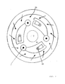
- a surface melting furnace (1) a so-called KSMF melting furnace
- the abbreviation KSMF stands for KUBOTA Surface Melting Furnace.
- the KSMF melting furnace (1) and its handling are u. a. in the prospectus "KUBOTA Melting Furnace for Sewage Sludge" of KUBOTA Corporation, Osaka, Japan.
- the melting furnace (1) also referred to as furnace (1), consists of a cylindrical outer jacket (8) in which a cylindrical inner jacket (9) is hung concentrically.
- the outer jacket (8) rotates at 0.5 to 5 U / h.
- the ring shaft (3) and the primary chamber (2) are formed between the outer jacket (8) and the inner jacket (9).
- the inner jacket (9) can be raised and lowered, whereby the size of the primary chamber (2) and the ring shaft (3) is adapted to the required capacity.
- At least one burner (7) whose flame (11) burns in the primary chamber (2) is arranged in the interior (14) of the inner jacket (9).
- the interior (14) is closed with a movable furnace cover (15).
- the surface melting furnace (1) has a funnel (12) for filling the material, in which two double pendulum flaps (13) are arranged, whereby the surface melting furnace (1) is secured against the ingress of false air.
- Water seals (17, 18) are usually fitted between the fixed furnace cover (16) and the rotating outer jacket (8) and the fixed inner jacket (9). There is another water seal (21) on the surface melting furnace (1).
- the water seals (17, 18, 21) offer an absolutely gas-tight seal and ensure quick pressure equalization when pressure increases.
- labyrinth seals (10a) or slip ring seals (10b) are provided, which reliably prevent the discharge of asbestos-containing dusts from the surface melting furnace.
- an outlet (4) also referred to as a slag discharge, is attached centrally.
- the outlet (4) forms the connection between the primary chamber (2) and the secondary chamber (5).
- the outlet for the melt from the secondary chamber (5) is in a water bath (19).
- a gas-tight seal is achieved by the water bath (19).
- the water bath (19) is connected to the wet slag remover (6).
- the flue gases are withdrawn from the secondary chamber (5) via the outlet (20) and cleaned and removed in a manner known per se.
- the material is poured into the ring shaft (3) via the funnel (12) and evenly distributed by rotating the outer casing (8) - the material in the ring shaft (3) is erased from the Bottom edge of the fixed inner jacket (9) in a cone shape towards the central outlet (4) of the primary chamber (2).
- the actual reaction space for the melting process is created in this way.
- the flame (11) of the burner (7) causes the melting process.
- a 2 cm to 5 cm thick, molten surface layer is created on the surface of the material.
- the flowing melt leaves the primary chamber (2) together with the flue gases through the central outlet (4).
- the melt falls through the secondary chamber (5) into the water bath (19), where it granulates.
- the wet slag remover (6) conveys the granules with a grain size ⁇ 10 mm to the outside.
- Fig. 2 shows the arrangement of three burners (7, 7 ', 7 ") and three inlet openings (22, 22', 22") for secondary air as well as several inlet openings (23) for tertiary air evenly distributed in the outer circle in the furnace ceiling (10 ) of the primary chamber (2) of the surface melting furnace (1).
- the flames (11, 11 ', 11 ") of the burners (7, 7', 7") burn in the primary chamber (2).
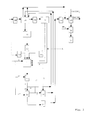
- FIG. 3 shows a flow diagram of the method according to the invention.
- Material is put into a pyrolysis furnace [pyrolysis drum] (24) from a waste bunker (28).
- the pyrolysis gas with a temperature of 400 ° C to 700 ° C is passed from the pyrolysis furnace (24) into a gas cooling system (29).
- the pyrolysis gas is passed from the gas cooling (29) into a dust separator (30) and dedusted.
- the dust is removed from the dust separator (30) via line (A).
- Line (A) is branched into lines (A ') and (A ").
- the pyrolysis gas is fed via line (A') into the surface melting furnace (1) and via line (A") into the combustion chamber (26). headed.
- the pyrolyzed material is passed from the pyrolysis furnace (24) into the magnetic separator (31). Iron-containing material is separated in the magnetic separator (31). The ferrous material is discharged. The material is transferred from the magnetic separator (31) to a sieve (32). The material with a grain size ⁇ 50 mm is placed in the KSFM furnace (1). The material with a grain size> 50 mm is crushed in a crusher (38) and placed in the surface melting furnace (1). The high calorific value material shredded in the shredder (39) can be placed in the surface melting furnace (1). The exhaust gas from the surface melting furnace (1) is passed into an afterburning (33) and discharged from the afterburning (33) via line (B).
- the line (B) is branched into lines (B ') and (B ").
- the exhaust gas from the afterburning (33) reaches the pyrolysis furnace via line (B') at a temperature of 1000 ° C. to 1100 ° C. (24).
- the exhaust gas reaches the recuperator (25) via line (B "). 20% by volume to 50% by volume of the exhaust gas from the surface melting furnace (1) are passed into the pyrolysis furnace (24) and 40% by volume to 80% by volume of the exhaust gas are passed into the recuperator (25).
- the exhaust gas is cooled to 300 ° C to 500 ° C in the recuperator (25).
- 30 vol .-% to 80 vol .-% of the warmed air are introduced from the recuperator (25) via line (C ') into the surface melting furnace (1).
- the remaining air is introduced via line (C) into the combustion chamber (26), in which the remaining pyrolysis gas is burned.
- the exhaust gas from the combustion chamber (26) is passed into the pyrolysis furnace (24) at a temperature of approximately 1000 ° C.
- the exhaust gas from the recuperator (25) is passed into a quench (27) and cooled to 180 ° C. to 260 ° C. and passed out of the quench (27) into a residual dust separator (34).
- the residual dust is removed from the residual dust separation (34).
- the exhaust gas from the residual dust separation (34) is combined with the heating gases from the pyrolysis furnace (24).
- the heating gases are passed into the pyrolysis furnace (24) from the combustion chamber (26) and via line (B ').
- the combined gases are passed to the two-stage flue gas cleaning system (35).
- Ca (OH) 2 is introduced into the two-stage flue gas cleaning system (35), and salts are removed from the flue gas cleaning system (35).
- NH 3 is introduced into the SCR (36).
- the gas is then passed into a chimney (37).
- 150 kg sprayed asbestos with a melting point of 1550 ° C were crushed to a grain size of ⁇ 50 mm in a hammer mill.
- 50 kg of filter dust from a domestic waste incineration plant and 50 kg of dried sewage sludge (> 80% dry matter) were mixed into the crushed spray asbestos.
- the 250 kg mixture was continuously introduced into the primary chamber of a KSMF melting furnace with an inner diameter of 2 m.
- the required melting energy was generated in the primary chamber by burning 95 kg of heating oil.
- An oxygen content of 3.5% by volume was set in the secondary chamber.
- melt product had a density of 3 g / cm 3 and was 70% present as olivine and entstatite, serpentine was not detected.
- the exhaust gas from the secondary chamber had a NO x Content of 150 mg / Nm 3 and a CO content of 10 mg / Nm 3 .
- the activated coke was comminuted in a vibrating mill to a grain size ⁇ 500 ⁇ m, 80% ⁇ 80 ⁇ m.
- the activated coke and the oil were mixed and introduced through three burners.
- An oxygen content of 6.5% by volume was set in the secondary chamber.
- the temperature of the exhaust gas from the primary chamber drops to 1020 ° C. in the secondary chamber after a dwell time of 2 seconds. 1385 kg / h of melt granulate with a grain size of 1 mm to 5 mm were discharged from the wet slag remover.
- the melt product had a density of 3 g / Nm 3. 11000 Nm 3 / h exhaust gas were measured at the outlet of the secondary chamber.
- the exhaust gas from the secondary chamber had a NO x content of 180 mg / Nm 3 and a CO content of 15 mg / Nm 3 .
- the remaining 50 vol .-% were placed in a combustion chamber in which the pyrolysis gas was burned.
- the exhaust gases from the recuperator cooled to 450 ° C, were introduced into a quench. In the quench, the temperature of the exhaust gases was reduced to 220 ° C. by injecting water. The exhaust gases were fed to a known exhaust gas cleaning system.
- Example 4 was carried out as in Example 3, in which the combustion air was enriched with oxygen to 30% by volume 0 2 .
- the amount of heating oil has been reduced to 25 kg.
- the amount of flue gas produced was reduced by 30%.
- 135 kg of melt granulate with a grain size of 1 mm to 5 mm were discharged from the wet slag remover.
- Example 5 was carried out as in Example 3, in which pyrolysis gas was introduced into the KSMF melting furnace. The amount of heating oil has been reduced to 10 kg. 135 kg of melt granulate with a grain size of 1 mm to 5 mm were discharged from the wet slag remover.
Priority Applications (1)
| Application Number | Priority Date | Filing Date | Title |
|---|---|---|---|
| EP97117638A EP0823266A1 (fr) | 1994-05-26 | 1995-05-20 | Procédé et appareil pour l'élimination de coke carbonisé et/ou de poussière de pyrolyse |
Applications Claiming Priority (6)
| Application Number | Priority Date | Filing Date | Title |
|---|---|---|---|
| DE4418410A DE4418410C1 (de) | 1994-05-26 | 1994-05-26 | Verfahren zum Einschmelzen von Asbest und/oder asbesthaltigem Material |
| DE4418410 | 1994-05-26 | ||
| DE4443088A DE4443088C1 (de) | 1994-12-03 | 1994-12-03 | Verfahren zum Entsorgen von Reststoffen aus Abfallverbrennungsanlagen sowie Aktivkoks und/oder Aktivkohle |
| DE4443090A DE4443090C1 (de) | 1994-12-03 | 1994-12-03 | Verfahren zum Entsorgen von Schwelkoks und/oder Pyrolysestaub |
| DE4443088 | 1994-12-03 | ||
| DE4443090 | 1994-12-03 |
Related Child Applications (1)
| Application Number | Title | Priority Date | Filing Date |
|---|---|---|---|
| EP97117638A Division EP0823266A1 (fr) | 1994-05-26 | 1995-05-20 | Procédé et appareil pour l'élimination de coke carbonisé et/ou de poussière de pyrolyse |
Publications (1)
| Publication Number | Publication Date |
|---|---|
| EP0684054A1 true EP0684054A1 (fr) | 1995-11-29 |
Family
ID=27206428
Family Applications (2)
| Application Number | Title | Priority Date | Filing Date |
|---|---|---|---|
| EP97117638A Withdrawn EP0823266A1 (fr) | 1994-05-26 | 1995-05-20 | Procédé et appareil pour l'élimination de coke carbonisé et/ou de poussière de pyrolyse |
| EP95107704A Withdrawn EP0684054A1 (fr) | 1994-05-26 | 1995-05-20 | Procédé et appareil pour la fusion de l'amiante ou des matériaux contenant de l'amiante |
Family Applications Before (1)
| Application Number | Title | Priority Date | Filing Date |
|---|---|---|---|
| EP97117638A Withdrawn EP0823266A1 (fr) | 1994-05-26 | 1995-05-20 | Procédé et appareil pour l'élimination de coke carbonisé et/ou de poussière de pyrolyse |
Country Status (3)
| Country | Link |
|---|---|
| EP (2) | EP0823266A1 (fr) |
| FI (1) | FI952579A (fr) |
| NO (1) | NO952065L (fr) |
Cited By (7)
| Publication number | Priority date | Publication date | Assignee | Title |
|---|---|---|---|---|
| EP0742032A2 (fr) * | 1995-05-03 | 1996-11-13 | ENEL S.p.A. | Procédé pour la vitrification des matériaux composites contenant de l'amiante |
| WO1998003438A1 (fr) * | 1996-07-24 | 1998-01-29 | Termo D.D., Industrija Termic^¿Nih Izolacij, S^¿Kofjaloka | Procede et dispositif de renvoi de dechets metalliques dans un cubilot |
| EP1469253A1 (fr) * | 2002-11-07 | 2004-10-20 | Tokyo Elex Co., Ltd. | Procede de traitement des dechets et installation de traitement |
| EP2027943A1 (fr) | 2007-07-31 | 2009-02-25 | Ivano Zanatto | Processus industriel pour la recristallisation induite à la température directe de l'amiante et/ou des fibres minérales contenant des produits de déchets utilisant un four tunnel et recyclage |
| WO2014140551A1 (fr) * | 2013-03-11 | 2014-09-18 | Envirofusion Ltd | Réacteur de traitement de matière première |
| FR3032635A1 (fr) * | 2015-02-13 | 2016-08-19 | O T N D Onet Tech Nuclear Decommissioning | Procede de destruction de dechets amiantes et installation de destruction de dechets amiantes |
| CN116555571A (zh) * | 2023-04-27 | 2023-08-08 | 上海开鸿环保科技有限公司 | 危废污泥电热熔融资源化处理装置 |
Families Citing this family (1)
| Publication number | Priority date | Publication date | Assignee | Title |
|---|---|---|---|---|
| DE10160756A1 (de) * | 2001-12-11 | 2003-06-18 | Fritz Schoppe | Verfahren zum Verbrennen von Abfällen und Vorrichtung zum Behandeln der Abgase einer Abfallverbrennung |
Citations (4)
| Publication number | Priority date | Publication date | Assignee | Title |
|---|---|---|---|---|
| EP0265051A1 (fr) * | 1986-08-26 | 1988-04-27 | Czerwinski, Jan | Procédé et appareil pour rendre l'amiante inoffensif pour l'environnement |
| US4808198A (en) * | 1988-02-01 | 1989-02-28 | Texaco Inc. | Environmentally safe method for disposing of asbestos containing materials |
| JPH02303585A (ja) | 1989-05-17 | 1990-12-17 | Kubota Corp | 石綿溶融方法 |
| DE4301977C1 (de) * | 1993-01-26 | 1994-01-05 | Ehlert Umwelttechnik Gmbh Dr | Verfahren zum Entsorgen von asbesthaltigem Gut |
Family Cites Families (5)
| Publication number | Priority date | Publication date | Assignee | Title |
|---|---|---|---|---|
| DE1401896A1 (de) * | 1959-11-11 | 1969-03-27 | Wotschke Dr Ing Johannes | Verfahren zum Hochtemperatur-Zerlegen schwieriger besonders Abfall-Brennstoffe |
| JPS5860113A (ja) * | 1981-10-05 | 1983-04-09 | Kubota Ltd | 廃棄物の溶融処理方法 |
| JPS6099921A (ja) * | 1983-11-02 | 1985-06-03 | Tokyo Gas Co Ltd | 焼却灰の溶融処理方法 |
| JPS6370014A (ja) * | 1986-09-09 | 1988-03-30 | Daido Steel Co Ltd | サイクロン型下水汚泥焼却溶融炉 |
| RU2141076C1 (ru) * | 1993-04-06 | 1999-11-10 | Осмелт Лимитед | Способ обработки углеродсодержащего материала |
-
1995
- 1995-05-20 EP EP97117638A patent/EP0823266A1/fr not_active Withdrawn
- 1995-05-20 EP EP95107704A patent/EP0684054A1/fr not_active Withdrawn
- 1995-05-24 NO NO952065A patent/NO952065L/no unknown
- 1995-05-26 FI FI952579A patent/FI952579A/fi unknown
Patent Citations (4)
| Publication number | Priority date | Publication date | Assignee | Title |
|---|---|---|---|---|
| EP0265051A1 (fr) * | 1986-08-26 | 1988-04-27 | Czerwinski, Jan | Procédé et appareil pour rendre l'amiante inoffensif pour l'environnement |
| US4808198A (en) * | 1988-02-01 | 1989-02-28 | Texaco Inc. | Environmentally safe method for disposing of asbestos containing materials |
| JPH02303585A (ja) | 1989-05-17 | 1990-12-17 | Kubota Corp | 石綿溶融方法 |
| DE4301977C1 (de) * | 1993-01-26 | 1994-01-05 | Ehlert Umwelttechnik Gmbh Dr | Verfahren zum Entsorgen von asbesthaltigem Gut |
Non-Patent Citations (1)
| Title |
|---|
| PATENT ABSTRACTS OF JAPAN vol. 015, no. 080 (C - 0810) 25 February 1991 (1991-02-25) * |
Cited By (11)
| Publication number | Priority date | Publication date | Assignee | Title |
|---|---|---|---|---|
| EP0742032A2 (fr) * | 1995-05-03 | 1996-11-13 | ENEL S.p.A. | Procédé pour la vitrification des matériaux composites contenant de l'amiante |
| EP0742032A3 (fr) * | 1995-05-03 | 1997-01-02 | Enel Spa | Procédé pour la vitrification des matériaux composites contenant de l'amiante |
| WO1998003438A1 (fr) * | 1996-07-24 | 1998-01-29 | Termo D.D., Industrija Termic^¿Nih Izolacij, S^¿Kofjaloka | Procede et dispositif de renvoi de dechets metalliques dans un cubilot |
| EP1469253A1 (fr) * | 2002-11-07 | 2004-10-20 | Tokyo Elex Co., Ltd. | Procede de traitement des dechets et installation de traitement |
| EP1469253A4 (fr) * | 2002-11-07 | 2007-01-03 | Tokyo Elex Co Ltd | Procede de traitement des dechets et installation de traitement |
| US7392753B2 (en) | 2002-11-07 | 2008-07-01 | Tokyo Elex Co., Ltd. | Process and apparatus for disposal of wastes |
| EP2027943A1 (fr) | 2007-07-31 | 2009-02-25 | Ivano Zanatto | Processus industriel pour la recristallisation induite à la température directe de l'amiante et/ou des fibres minérales contenant des produits de déchets utilisant un four tunnel et recyclage |
| WO2014140551A1 (fr) * | 2013-03-11 | 2014-09-18 | Envirofusion Ltd | Réacteur de traitement de matière première |
| EP2971960A1 (fr) * | 2013-03-11 | 2016-01-20 | Envirofusion Ltd | Réacteur de traitement de matière première |
| FR3032635A1 (fr) * | 2015-02-13 | 2016-08-19 | O T N D Onet Tech Nuclear Decommissioning | Procede de destruction de dechets amiantes et installation de destruction de dechets amiantes |
| CN116555571A (zh) * | 2023-04-27 | 2023-08-08 | 上海开鸿环保科技有限公司 | 危废污泥电热熔融资源化处理装置 |
Also Published As
| Publication number | Publication date |
|---|---|
| FI952579A0 (fi) | 1995-05-26 |
| EP0823266A1 (fr) | 1998-02-11 |
| NO952065L (no) | 1995-11-27 |
| FI952579A (fi) | 1995-11-27 |
| NO952065D0 (no) | 1995-05-24 |
Similar Documents
| Publication | Publication Date | Title |
|---|---|---|
| DE4446803C2 (de) | Verfahren und Vorrichtung zur thermischen und stofflichen Verwertung von Rest- und Abfallstoffen | |
| DE19608093C2 (de) | Verfahren zur Verwertung von Rest- und Abfallstoffen sowie heizwertarmen Brennstoffen in einem Zementofen | |
| EP0394391B1 (fr) | Procede et dispositif de traitement de scories et autres residus de combustion provenant d'installations d'incineration de dechets | |
| DE2624971C2 (de) | Verfahren zur Verwertung industrieller Abfälle | |
| DE4107200A1 (de) | Verfahren und anlage zur thermischen abfallbehandlung | |
| EP0545241A1 (fr) | Procédé pour la valorisation thermique de déchets | |
| EP0572769B1 (fr) | Procédé pour la conversion des résidus de l'incinération de déchets en produit non-polluant et utilisable pour la construction | |
| EP0293982B1 (fr) | Procédé pour le traitement de matières minérales contaminées | |
| EP0908673B1 (fr) | Procédé de traitement de scories provenants du traitement thermique de déchets | |
| DE4339675C1 (de) | Verfahren und Vorrichtung zum Einschmelzen von festen Verbrennungsrückständen | |
| DE19522457C2 (de) | Verfahren zum Behandeln von Hausmüll | |
| EP0143106B1 (fr) | Procédé pour retravailler des résidus contenant des métaux lourds en provenance de l'industrie chimique | |
| EP0684054A1 (fr) | Procédé et appareil pour la fusion de l'amiante ou des matériaux contenant de l'amiante | |
| DE4443088C1 (de) | Verfahren zum Entsorgen von Reststoffen aus Abfallverbrennungsanlagen sowie Aktivkoks und/oder Aktivkohle | |
| DE4109063C2 (de) | Verfahren zur gleichzeitigen Verwertung von stückigen und fließfähigen brennbaren Abfallstoffen und Rückständen | |
| DE3920760A1 (de) | Verfahren zur thermischen entsorgung von abfallstoffen bzw. reststoffen wie z.b. aschen, klaerschlamm oder dergleichen | |
| DE4418410C1 (de) | Verfahren zum Einschmelzen von Asbest und/oder asbesthaltigem Material | |
| EP0815393B1 (fr) | Procede de traitement d'ordures menageres | |
| EP0380566B1 (fr) | Procede d'elimination de dechets par combustion enrichie avec de l'oxygene | |
| EP1583811A1 (fr) | Gazeificateur a fusion en cuve et procede de traitement thermique et de valorisation de dechets | |
| EP0712811B1 (fr) | Procédé de traitement thermique des déchets | |
| DE102012218878A1 (de) | Thermische Behandlung von Mineralwolle | |
| DE4443090C1 (de) | Verfahren zum Entsorgen von Schwelkoks und/oder Pyrolysestaub | |
| EP0852692B1 (fr) | Procede de fusion de scories et de residus de combustion a oxydes, et dispositif permettant la mise en oeuvre de ce procede | |
| EP0693306B1 (fr) | Procédé de fabrication des matières secondaires brutes à partir des déchets |
Legal Events
| Date | Code | Title | Description |
|---|---|---|---|
| PUAI | Public reference made under article 153(3) epc to a published international application that has entered the european phase |
Free format text: ORIGINAL CODE: 0009012 |
|
| AK | Designated contracting states |
Kind code of ref document: A1 Designated state(s): AT BE CH DE DK ES FR GR IT LI LU NL PT SE |
|
| 17P | Request for examination filed |
Effective date: 19960529 |
|
| 17Q | First examination report despatched |
Effective date: 19970619 |
|
| STAA | Information on the status of an ep patent application or granted ep patent |
Free format text: STATUS: THE APPLICATION HAS BEEN WITHDRAWN |
|
| 18W | Application withdrawn |
Withdrawal date: 19980921 |
|
| RAP1 | Party data changed (applicant data changed or rights of an application transferred) |
Owner name: METALLGESELLSCHAFT AKTIENGESELLSCHAFT |