EP0683653B1 - Spinales befestigungssystem - Google Patents
Spinales befestigungssystem Download PDFInfo
- Publication number
- EP0683653B1 EP0683653B1 EP94907143A EP94907143A EP0683653B1 EP 0683653 B1 EP0683653 B1 EP 0683653B1 EP 94907143 A EP94907143 A EP 94907143A EP 94907143 A EP94907143 A EP 94907143A EP 0683653 B1 EP0683653 B1 EP 0683653B1
- Authority
- EP
- European Patent Office
- Prior art keywords
- stem
- rod
- spinal
- bore
- threaded
- Prior art date
- Legal status (The legal status is an assumption and is not a legal conclusion. Google has not performed a legal analysis and makes no representation as to the accuracy of the status listed.)
- Expired - Lifetime
Links
Images


Classifications
-
- A—HUMAN NECESSITIES
- A61—MEDICAL OR VETERINARY SCIENCE; HYGIENE
- A61B—DIAGNOSIS; SURGERY; IDENTIFICATION
- A61B17/00—Surgical instruments, devices or methods, e.g. tourniquets
- A61B17/56—Surgical instruments or methods for treatment of bones or joints; Devices specially adapted therefor
- A61B17/58—Surgical instruments or methods for treatment of bones or joints; Devices specially adapted therefor for osteosynthesis, e.g. bone plates, screws, setting implements or the like
- A61B17/68—Internal fixation devices, including fasteners and spinal fixators, even if a part thereof projects from the skin
- A61B17/70—Spinal positioners or stabilisers ; Bone stabilisers comprising fluid filler in an implant
- A61B17/7049—Connectors, not bearing on the vertebrae, for linking longitudinal elements together
-
- A—HUMAN NECESSITIES
- A61—MEDICAL OR VETERINARY SCIENCE; HYGIENE
- A61B—DIAGNOSIS; SURGERY; IDENTIFICATION
- A61B17/00—Surgical instruments, devices or methods, e.g. tourniquets
- A61B17/56—Surgical instruments or methods for treatment of bones or joints; Devices specially adapted therefor
- A61B17/58—Surgical instruments or methods for treatment of bones or joints; Devices specially adapted therefor for osteosynthesis, e.g. bone plates, screws, setting implements or the like
- A61B17/68—Internal fixation devices, including fasteners and spinal fixators, even if a part thereof projects from the skin
- A61B17/70—Spinal positioners or stabilisers ; Bone stabilisers comprising fluid filler in an implant
- A61B17/7001—Screws or hooks combined with longitudinal elements which do not contact vertebrae
- A61B17/7002—Longitudinal elements, e.g. rods
-
- A—HUMAN NECESSITIES
- A61—MEDICAL OR VETERINARY SCIENCE; HYGIENE
- A61B—DIAGNOSIS; SURGERY; IDENTIFICATION
- A61B17/00—Surgical instruments, devices or methods, e.g. tourniquets
- A61B17/56—Surgical instruments or methods for treatment of bones or joints; Devices specially adapted therefor
- A61B17/58—Surgical instruments or methods for treatment of bones or joints; Devices specially adapted therefor for osteosynthesis, e.g. bone plates, screws, setting implements or the like
- A61B17/68—Internal fixation devices, including fasteners and spinal fixators, even if a part thereof projects from the skin
- A61B17/70—Spinal positioners or stabilisers ; Bone stabilisers comprising fluid filler in an implant
- A61B17/7001—Screws or hooks combined with longitudinal elements which do not contact vertebrae
- A61B17/7041—Screws or hooks combined with longitudinal elements which do not contact vertebrae with single longitudinal rod offset laterally from single row of screws or hooks
-
- A—HUMAN NECESSITIES
- A61—MEDICAL OR VETERINARY SCIENCE; HYGIENE
- A61B—DIAGNOSIS; SURGERY; IDENTIFICATION
- A61B17/00—Surgical instruments, devices or methods, e.g. tourniquets
- A61B17/56—Surgical instruments or methods for treatment of bones or joints; Devices specially adapted therefor
- A61B17/58—Surgical instruments or methods for treatment of bones or joints; Devices specially adapted therefor for osteosynthesis, e.g. bone plates, screws, setting implements or the like
- A61B17/68—Internal fixation devices, including fasteners and spinal fixators, even if a part thereof projects from the skin
- A61B17/70—Spinal positioners or stabilisers ; Bone stabilisers comprising fluid filler in an implant
- A61B17/7047—Clamps comprising opposed elements which grasp one vertebra between them
-
- A—HUMAN NECESSITIES
- A61—MEDICAL OR VETERINARY SCIENCE; HYGIENE
- A61B—DIAGNOSIS; SURGERY; IDENTIFICATION
- A61B17/00—Surgical instruments, devices or methods, e.g. tourniquets
- A61B17/56—Surgical instruments or methods for treatment of bones or joints; Devices specially adapted therefor
- A61B17/58—Surgical instruments or methods for treatment of bones or joints; Devices specially adapted therefor for osteosynthesis, e.g. bone plates, screws, setting implements or the like
- A61B17/68—Internal fixation devices, including fasteners and spinal fixators, even if a part thereof projects from the skin
- A61B17/70—Spinal positioners or stabilisers ; Bone stabilisers comprising fluid filler in an implant
- A61B17/7001—Screws or hooks combined with longitudinal elements which do not contact vertebrae
- A61B17/7002—Longitudinal elements, e.g. rods
- A61B17/7004—Longitudinal elements, e.g. rods with a cross-section which varies along its length
- A61B17/7005—Parts of the longitudinal elements, e.g. their ends, being specially adapted to fit in the screw or hook heads
Definitions
- the present invention concerns a spinal fixation system, particularly a system for posterior fixation of the spine for the treatment of spinal deformities.
- the system contemplates various components interconnected together by way of elongated rods extending along the spinal column.
- a number of fixation hooks 13 are engaged to the rods by eyebolts 14 at various vertebral levels along the construction. These hooks are of well known construction and include a claw for grabbing segments of a specific vertebra.
- the TSRH® system also provides means for engaging the sacrum for a firm foundation for the rigid construct.
- a transverse connector 15, provided by Danek as its Cross Link® connector, provides lateral engagement between the parallel rods. In known constructions, a number of transverse connectors 15 can be situated at various locations along the rods as necessary to provide an adequate and stable construct.
- TSRH® spinal system as well as other systems of this type, permit rigid and semi-rigid segmental instrumentation of the spine using a selection of hooks, and in some instances bone screws or bolts that engage the pedicle of the vertebra.
- hooks attached to the rods exert forces at key points of the deformed spine to correct the particular deformity of spinal curvature.
- other rod systems provide mechanisms for longitudinal distraction and compression of the hooks as required to account for the particular medical indication.
- the hook and rod systems provide a means for maintaining correct positioning of vertebrae during a vertebral fusion process as may be indicated to correct painful disc syndrome or degenerative disc disease.
- a further area of improvement for the hook and rod spinal systems concerns the ease of assembling the system.
- EP-A-0441084 discloses a spinal fixation system in which a bone-engaging screw has an upper threaded part that is affixed to either a rod or a plate by means of a connection element. A nut is threaded onto the upper threaded part of the screw to clamp the connection element to the rod or plate.
- the present invention contemplates a spinal implant system for correcting spinal deformities and abnormalities that uses an elongated spinal rod configured to be implanted adjacent the spinal column and spanning across several vertebral levels.
- a number of fixation elements such as spinal hooks, are provided for engaging vertebrae at a number of vertebral levels.
- at least some of the fixation elements includes an elongated stem projecting from the vertebra engaging portion.
- rod connector means are provided for connecting the stem of each fixation element to the spinal rod.
- the rod connector means includes a connector having a one-piece body defining a rod channel adapted to receive the spinal rod therethrough, a stem bore adapted to receive a stem therethrough, and a threaded bore.
- a threaded set screw is provided which is adapted to be received within the threaded bore.
- the stem bore has a length through the body and the rod channel intersects the stem bore along a portion of this length to permit contact between the rod and the stem of a fixation element when the rod is received within the rod channel and the stem is received within the stem bore.
- the threaded bore intersects the stem bore to permit contact between the set screw and the stem within the stem bore as the set screw is threaded into the threaded bore. As the set screw is threaded further into the threaded bore, it presses the stem against the spinal rod to provide a clamped engagement and to restrain relative movement between the rod and the fixation element.
- the threaded bore intersects the rod channel so that the set screw bears against the spinal rod when the rod is within the rod channel. In this embodiment, as the set screw is threaded further into the threaded bore, it presses the rod against the stem of the fixation element to again provide a clamped engagement between the rod and the stem of the fixation element.
- the connector body of the rod connector means further defines a channel opening extending to the rod channel which is sized to permit passage of the spinal rod therethrough when the rod is to be received within the rod channel.
- This channel opening permits "top-loading" of the rod connector means when the spinal rod is already in position adjacent the spinal column.
- the stem bore in the connector body has an elongated cross-section with a length along the long axis of the cross-section that is greater than the width of the fixation element stem. This greater length allows the stem to move back within the stem bore to allow the connector body to engage the spinal rod even when the stem is extending through the stem bore.
- the stem of the fixation elements can include a groove defined along the length of the stem, the groove forming opposite groove tips adapted to firmly grip the spinal rod.
- the spinal rod can further include a spiral groove formed along its length, with the groove tips of the fixation element stem sized to fit within the spinal rod spiral groove. This feature of the invention adds a greater element of security against the fixation element stem sliding along the length of the spinal rod.
- the spinal implant system of the present invention further contemplates a lateral offset coupler which permits adjustment of the lateral position of a fixation element relative to the spinal rod.
- the lateral offset coupler includes an offset body with means for engaging a fixation element, and a stem extending from the offset body.
- the stem is preferably configured identically to the fixation element stem described above so that the same rod connector means can be used to connect the lateral offset coupler to the spinal rod.
- the offset body is perpendicularly offset from the stem to permit superior/inferior offset of the fixation element when the lateral offset coupler is connected to the spinal rod.
- One feature common to the stem of the fixation elements and the stem of the lateral offset coupler resides in external threads formed along a portion of the length of both stems.
- the threads are adapted to receive a correspondingly threaded nut which forms part of a means for temporarily fastening the components to the rod connector means.
- the stem is long enough to extend significantly above the level of the spinal rod when the rod is initially positioned near the spinal column.
- the nut can be threaded onto the threads of the fixation element stem.
- the present invention provides for a method of implanting a spinal system in which the bulk of the instrumentation procedure can be accomplished at a level dorsal to the instrumented vertebrae, allowing easier unencumbered assembly.
- the construct can be drawn anteriorly down to its final implant level adjacent the vertebrae by threading each of the nuts down on the threaded stems of the fixation elements.
- the set screws in each of the rod connector means can be tightened to firmly clamp rod to fixation element, thereby completing the implant construct.
- the same components can be used as a reduction apparatus to draw a misplaced vertebra into alignment with adjacent properly positioned vertebrae.
- a further object resides in features of the present inventive system that provide top-loading of rod connectors that can be used in a variety of orientations to connect fixation elements, transverse connectors and lateral couplers alike.
- a benefit attained by the present invention is the ability to initially instrument the spine at a higher posterior level and then subsequently draw the construct down to its final position adjacent the vertebrae.
- a further object resides in providing a system that allows the surgeon to add vertebral fixation elements or change the position or level of instrumentation while the spinal rod is oriented along the spinal column.
- Yet another object of the invention is to provide an implant system having a reduced profile from prior rod systems.
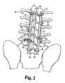
- the system includes a pair of bendable elongated spinal rods 21 situated on opposite sides of the spinal column and particularly the sagittal plane.
- the rods 21 as depicted in FIG. 2 are shown extending from the sacrum to the upper lumbar vertebrae. It is understood, of course, that the rods can extend to the thoracic vertebrae or between any group of vertebrae in the spinal column as indicated to correct the particular spinal deformity or treat the specific spinal problem.
- fixation hooks 25 are engaged to the rod 21 at various locations along the vertebral column. As in prior spinal fixation systems, such as the TSRH® system described above, these fixation hooks engage predetermined segments of the spinal column to provide the appropriate forces for fixation or correction of spinal deformities.
- Each of the fixation hooks 25 is engaged to a respective rod 21 by way of a rod connector means 28.
- Other rod connectors means 29 are used to mount other components to the spinal rods 21, such as an offset coupler 32.
- the offset coupler 32 provides a means for supporting a bone screw 33 offset from the fixation position on the rod in the lateral and superior/inferior directions.
- the rod connector means 29 are also used to support a transverse coupler 35 which also engages a fixation screw 33 at variable lateral distances.
- a transverse connector 38 can be provided to add lateral stability and fixation between the two rods 21.
- FIGS. 3A-3C One embodiment of the rod connector means 28 is shown in FIGS. 3A-3C. It can be seen that the rod connector means 28 provide a means for engaging a fixation element, such as hook 25, to the spinal rod 21.
- the fixation hooks 25 includes an elongated stem 26 and an integral claw portion 27 which engages a portion of a vertebra.
- the rod connector means 28 includes a connector body 45 which defines a rod channel 47 through which the spinal rod 21 extends. In one specific embodiment, the rod channel 47 includes a channel opening 48 so that the rod connector means 28 can be "top-loaded" onto the spinal rod 21.
- the channel opening 48 can be eliminated so that the rod channel 47 is in effect a bore through the connector body 45.
- the rod connector means 28 must be preloaded onto the spinal rod prior to placement of the rod in the patient.
- the closed channel rod connector means would operate similar to the eyebolt fixation component of the TSRH® system previously described.
- the open channel configuration is preferred to retain the flexibility afforded by the top-loading capability. Top-loading means that a surgeon can add new fixation elements and rod connector means as necessary at virtually any stage of the spinal instrumentation procedure, even with the spinal rod in position adjacent the spine.
- the connector body 45 of the rod connector means 28 further defines a stem bore 49 which is oriented perpendicular to the rod channel 47 and which intersects the rod channel at an overlap portion 50.
- the stem bore is adapted to receive the fixation element stem 26 therethrough and, as can be seen more particularly in FIG. 3B, can be in the shape of an elongated slot that is larger than the general width of stem 26.
- the bore 49 include the bore/channel overlap 50 to permit the stem 26 of the fixation hook 25 to contact the rod 21 when the rod is situated within the rod channel 47.
- the body of the rod channel 47 defines a rod/channel overlap portion 51, as shown in FIG. 3B, which serves to retain the rod 21 within the channel 47.
- This pressure is provided by way of a set screw 58 which is threaded into a set screw bore 54.
- the set screw bore is oriented at an angle to both the stem bore 49 and the rod channel 47 and intersects the stem bore 49 at an intersection 55.
- a set screw 58 threaded into the bore 54 can contact and apply pressure to the hook stem 26.
- the curved tip 58a of the screw applies pressure to the stem and clamps the stem 26 and the rod 21 between the connector body 45 and the set screw 58.
- the set screw 58 includes a driving head 59 which can be of a typical hex configuration.
- the driving head 59 is a hex head extending beyond the surface of the connector body 45, the angular orientation of the set screw bore 54 helps to reduce the posterior profile of the rod connector means 28.
- this particular angular orientation of the set screw 58 often facilitates Lightening the set screw within the bore 54.
- the driving head 59 can be replaced by a hex recess for engagement to an alien head tool.
- the rod 21 of one specific embodiment includes a feature for preventing the rod connector means 28 from shifting along the length of the rod 21.
- the rod 21 includes a spiral groove 22 formed in the outer surface of the rod, as shown in FIGS. 3B and 3C.
- the stem 26 of the fixation hook 25 can include a pair of shallow grooves 40 on opposite faces of the stem.
- the grooves form tips 41 at the edges of the grooves, which tips engage within the spiral groove 22 of the rod 21. It has been found that the interface between the groove tips 41 and the rod spiral groove 22 adds a greater degree of longitudinal stability to the rod connector means 28 to prevent the connector from sliding along the rod during or after instrumentation.
- the groove 40 in the hook stem 26 provides a contoured surface for receiving the oval point 58a of the set screw 58. This allows for maximum frictional contact between the set screw 58 and the hook stem 26, thereby reducing the likelihood of slippage in the posterior/anterior direction of the hook relative to the connector 28. It has been found that the groove tips 41 can deform slightly when pressed against the spinal rod 21, with or without the spiral groove 22, to provide an additional frictional fit.
- the rod connector means 60 includes a connector body 61 which defines a rod channel 63.
- the body further defines a channel opening 64 which opens generally laterally relative to the body 61.
- the body 61 also defines a stem bore 68 through which the stem 26' of a fixation hook 25' can extend.
- the channel opening 64 of the rod channel 63 is oriented at a somewhat anterior angle to the stem bore 68.
- the channel opening 48 extends generally parallel to the stem bore 49.
- the channel opening 64 of the connector body 61 is defined by a pair of parallel faces 64a and 64b. These parallel faces 64a and 64b provide a surface along which the connector 60 slides along the rod 21' when the connector is to be engaged to the rod. While the rod connector means 60 is intended to be a top-loaded component, similar to the rod connector means 28, the engagement of the connector 60 to the spinal rod 21 requires some degree of lateral manipulation to snap the rod through the channel opening 64 into the rod channel 63.
- the lower parallel face 64b includes a locking edge 65 at the channel opening 64 which helps retain the rod 21' within the rod channel 63.
- the stem bore 68 defines a bore/channel overlap 70, similar to that found in the rod connector means 28 of the previous embodiment.
- the stem 26' of a fixation hook 25' extends through the stem bore 68, the stem 26' can contact the rod 21'.
- This contact is maintained by way of a set screw 74 which is threaded into a set screw bore 72 at the upper arm of the channel 64, and particularly through the upper parallel face 64a.
- the set screw 74 includes a driving head 75 and a rod engaging taper 76 at the opposite end of this set screw.
- This taper 76 is generally conical in shape and has a curvature which approximates the curvature of the spinal rod 21'.
- the rod 21' does not include the spiral groove 22 described above.
- the stern 26' of the hook 25' does not include the grooves 40 in the opposite faces of the stem. It has been found that with this configuration of rod connector means 60, the three points of contact to the rod 21' essentially eliminate the need for the spiral groove 22 and stem groove 40.
- the rod 21' is clamped between the rod channel 63, particularly at the locking edge 65, the hook stem 26', and the tapered tip 76 of the set screw 74.
- the rod 21 is engaged only between the rod channel 47 and the grooved stem 26 of the hook 25.
- the manner in which the two rod connector means 28 and 60 snap on to the spinal rod 21 or 21' may dictate which of the particular connectors is used at a specific level of instrumentation. It has been found that either of the two connectors 28 or 60 provide a solid engagement of the fixation hook 25 or 25' to the longitudinal spinal rod.
- Both of the rod connector means 28 and 60 permit top-loading of the connector to connect the fixation element stems to the spinal rod.
- the channel openings (48 and 64) allow the spinal rod to be slipped into the respective rod channels 47 and 63.
- the corresponding stem bores 49 and 68 have an elongated cross-section in which the long axis of the cross-section is greater than the general width of the fixation element stem 26.
- the stem is allowed to slide to one end of the bores 49/68 providing clearance for the spinal rod to pass into the rod channels.
- this clearance is of greater importance to allow the rod to clear the rod/channel overlap 51.
- the rod connector means 60 eliminates some of this manipulation since the stem bore 68 is at the opposite end of the rod channel 63 from the channel opening 64.
- the offset coupler 32 provides a means for engaging a bone fastener 33 (either a screw or bolt) to the spinal rod 21.
- the offset coupler 32 includes a stem 79 (FIG. 6) which includes upper and lower grooves 80. The grooves define groove tips 81, as shown in FIG. 7.
- the offset coupler 32 further includes an offset body 83 which is oriented generally perpendicular to the stem 79. In addition, as shown in FIG. 5, the offset body 83 angles downward somewhat from the longitudinal axis of the stem 79 so that the screw bore 84 in the body 83 is at or below the level of the spinal rod 21.
- the bore 84 through the body 83 also includes upper and lower countersunk portions 85.
- the stem 79 of the offset coupler 32 can be engaged to the spinal rod 21 by way of a rod connector 29.
- the rod connector 29 can be the rod connector 28 or the rod connector 60.
- the rod/channel overlap 51 of the rod channel 47 is oriented at the underside, or anterior side, of the spinal rod 21, as opposed to the lateral engagement shown in FIG. 3A. This orientation of the rod connector 28/29 allows the stem 79 of the offset coupler 32 to contact the spinal rod 21 at the posterior, or top, side of the rod.
- the offset coupler 32 provides a means for engaging a bone fastener 33, such as a screw or bolt to the rod 21.
- a bone fastener 33 such as a screw or bolt to the rod 21.
- the details of the threaded fastener 33 is shown in FIG. 5.
- the fastener 33 includes bone engaging threads 88 which are adapted to be threaded into the pedicle of a vertebra, such as a lumbar vertebra.
- machine threads 89 which are adapted to engage a threaded nut 93.
- This intermediate portion 90 includes an upper arcuate surface 91 which is seated against the underside countersink 85 of the screw bore 84 in the offset body 83.
- the nut 93 includes an arcuate seat 94 which engages the upper countersink 85 in the offset body 83.
- the engagement between the countersinks 85 and the arcuate surfaces of the intermediate portion 90 and the nut 93 allows for some degree of angulation of the fastener 33 relative to the offset coupler 32.
- the ability to orient the threaded fastener 33 relative to the rod 21 enhances the ability of the surgeon to instrument the spine.
- the threaded fastener 33 need not include the arcuate surface 91 and can simply include a flat engagement surface, such as found in bone bolts having an integral hex driving nut feature.
- the threaded fastener 33 is a bone bolt
- the bolt would be first threaded into the particular vertebra at the level of instrumentation.
- the offset coupler 32 is then be engaged to the bolt and subsequently fastened to the spinal rod 21 by way of a rod connector 29.
- the offset coupler 32 may already be engaged to the rod 21 by a connector 29, after which the coupler 32 and threaded fastener 33 are pulled together and engaged.
- the threaded fastener 33 may be a bone screw which does not include an intermediate portion 90 that engages the underside of the offset body 83. In this instance, it can be expected that the offset body 83 is configured to project a little further below the spinal rod 21 to contact the surface of the vertebra when the screw is threaded into the bone.
- a transverse coupler 35 in accordance with the present invention is shown in FIGS. 8A and 8B.
- the transverse coupler 35 provides for lateral offset engagement of a threaded fastener 33 between the bone and spinal rod 21.
- the transverse coupler 35 is similar to the offset coupler 32 except that it does not include an anterior/posterior offset feature.
- the transverse coupler 35 includes a stem 96, which can be a grooved stem such as the stem 79 of the offset coupler 32.
- Integral with the stem 96 is an offset body 97, which includes an anterior offset portion 98 to bring the body 97 closer to the vertebra when the transverse coupler 35 is engaged to the spinal rod 21.
- the offset body 97 includes a screw slot 99 having upper and lower countersinks 100.
- the slot 99 can simply be a circular bore or can be somewhat elongated to allow for further variation in lateral position of the threaded fastener 33 relative to the transverse coupler 35.
- the respective stems 79 and 96 are long enough to allow for some lateral or transverse variation in position.
- the stems 79 and 96 can include threads along their length, such as threads 101 shown in FIG. 8B. These threads 101 are adapted to receive a nut which is threaded onto the stem when the stem is loosely disposed within a rod connector 29 in position on the spinal rod 21.
- the threads 101 and the additional temporary nut can be used to draw the transverse coupler 35, and particularly the threaded fastener 33 supported by the coupler, toward the spinal rod 21. That is, as the nut is threaded onto the threads 101, the rod 21 and the threaded fastener 33 are pulled together. Once the appropriate orientation of rod to fastener is achieved, the rod connector 29 and particularly the set screw of the rod connector, can be tightened to clamp the stem 96 to the rod 21. Once the rod connector 29 has clamped the transverse coupler 35 to the rod 21, the temporary nut can be removed and the excess portion of the stem extending beyond the rod connector can be sheared off and removed.
- the spinal fixation system 20 of the present invention further contemplates the use of a transverse connector 38 to provide transverse or lateral interconnection between the two spinal rods 21.
- the transverse connector 38 includes a stem 105 terminating at one end in a head portion 106.
- the stem of the transverse connector is configured to pass through stem bores of rod connectors 29 engaged to each of the two rods 21.
- the rod connectors 29 can be configured as either the rod connector 28 or 60.
- the rod connectors 29 can be configured as shown in FIG. 9 to include a rod channel 108 and a posteriorly oriented set screw bore 110.
- the stem bore 109 projects perpendicularly to the set screw bore 110, but parallel to the opening of the rod channel 108.
- the set screw 111 can include a hex head recess to receive an allen head tool.
- the rod connector 29 is readily adapted for receiving a driving tool directly posterior to the rod and transverse connector 38.
- the set screw 111 which is preferably similar to the set screw 58, which includes an oval point for engaging the stem 105 of the transverse connector 38.
- the stem 105 of the transverse connector 38 can be threaded to allow a temporary nut to be tightened onto the stern.
- the spinal rods 21 engaged by the rod connectors 29 are drawn together.
- the head 106 at the one end of the transverse connector 38 provides an additional reaction surface in combination with the temporary nut. Once the appropriate position between the two rods 21 has been achieved, the rod connectors 29 can be tightened to firmly engage the stem 105 of the transverse connector 38 to each of the rods, and the temporary nut removed.
- the dual hook connector 115 provides means for engaging a pair of hooks to a spinal rod by way of a single connector.
- the dual hook connector 115 includes a connector body 118 which receives the stems 24 of a pair of hooks.
- the hooks can be a hook such as hook 25 having a stem 26, as well as a differently configured laminar hook 116 having a stem 117.
- the two hooks can have their claws facing each other to engage the lamina of a vertebra therebetween.
- Each of the stems 2G and 117 extend through a respective stem bore 120 defined in the body 118.
- a pair of set screw bores 121 intersect the stem bores 120 so that a pair of set screws (not shown) can be threaded therein to clamp the stems to the spinal rod.
- the distance between the stem bores 120 and set screw bores 121 are established to permit sufficient space between the claws of the respective hooks 25 and 116 to engage the lamina at a particular vertebral level.
- the dual hook connector 115 can be configured in the style of the open connectors 28 or 60 described above. In other words, the invention contemplates a dual hook connector in which two open connectors, such as connector 28, are integrally disposed side-by-side to support two spinal hooks.
- a connector 115" shown in FIG. 10C is configured to utilize a single set screw 122 to clamp the stems 26" of laminar hooks to a spinal rod 21.
- the connector 115" includes a body 118" having a pair of parallel oblong stem bores 120" formed therein. Intersecting each of the stem bores 120" is a set screw bore 121".
- the set screw 122 when threaded into the bore 121" contacts both hook stems 26" to clamp them against the rod 21.
- the stems 26" can be circular in cross section, as shown in FIG. 10C, or can have a cross section as shown in FIG. 10B.
- This transverse coupler 130 includes a stem 131 and offset body 132 at one end of the stem.
- the offset body 132 is configured to support a threaded fastener 33 which is engaged to the body 132 by way of nut 93.
- the offset body 132 is at the same level as the stern 131 and does not include any posterior/anterior or superior/inferior offset.
- This transverse coupler 130, and particularly its stem 131 can be configured similar to the stem 96 of the coupler 35 to include a channel and outer threads.
- FIG. 11 a spinal rod 21" is shown instrumented with a pair of hooks 25" and a threaded fastener 33.
- the stems 26" of the hooks 25" are engaged to the rod 21" by way of a rod connector 29.
- the rod connector is the connector 29 having a hex recess set screw 111.
- the rod connector can be either of the rod connectors 28 or 60 previously described.
- the stems 26 of the hooks 25 are long enough to project significantly outward from the rod 21. These stems are shown in their configuration immediately after having been installed in the spine.
- the stems which are preferably about two inches long, allow more ready top-loading of the rod when the hooks are already engaged at the particular vertebral level.
- the vertebral hooks have a relatively short stem for engagement by the rod instrumentation. This adds to the "fiddle factor" in completing the instrumentation.
- the present invention contemplates a much longer stem to the hooks, which stem can be severed at a break line 125 once the hooks have been fastened to the spinal rod 21.
- the hooks are engaged at the vertebra with the stems extending posteriorly.
- the rod and rod connector 29 can then be top-loaded onto the stem with the hook stem extending through the bores in the connectors 29.
- a temporary nut 124 can be threaded onto the threads 123 of each of the hook stems 26 to draw the rod 21 and the instrumented vertebra together.
- the set screw 111 of the rod connector 29 can be tightened to clamp the stem 26 to the rod 21.
- the temporary nut 124 is removed and the stem shortened by severing at the break point 125.
- the spinal fixation system of the present invention can also be used as a reduction apparatus.
- a displaced vertebra V 1 is instrumented between two normally positioned vertebrae V 2 and V 3 .
- the spinal rod 21 is bent to approximate the spinal physiology of the subject vertebra.
- the normal vertebra V 1 and V 3 are engaged by the claws of spinal hooks 25.
- the hooks 25 are attached to the spinal rod 21 by way of rod connectors, such as rod connectors 29 described above.
- the displaced vertebra V 1 is instrumented with laminar hooks 135 and 137. Each of the hooks 135 and 137 has a corresponding elongated stem 136 and 138, respectively.
- the stems extend through a dual hook connector, such as connector 115 described with respect to FIGS. 10A and 10B.
- a pair of nuts 139 and 140 are threaded onto stems 136 and 138, respectively. As the nuts are tightened down onto their corresponding stems, the hooks 135 and 137 draw the displaced vertebra V 1 toward the spinal rod 21, in the direction of the arrows 142. The nuts 139 and 140 are continually tightened onto the stems 136 and 138 until the vertebra V 1 is in proper alignment relative to the other instrumented vertebrae V 2 and V 3 .
- the spinal fixation system includes multi-level instrumentation capabilities which can be used for two purposes.
- the first purpose is to permit instrumentation at a higher level above the vertebrae and then be drawn down to a level immediately adjacent the vertebrae.
- the second use' is as a reduction apparatus to draw a displaced vertebra into proper physiological alignment.
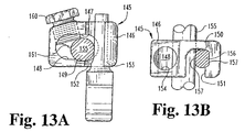
- the rod connector 145 includes a body 146 which defines a rod channel 147 therethrough.
- the rod channel 147 is generally oblong in shape and is defined by a pair of overlapping bores 148 and 149.
- the bore 148 has approximately the same diameter as the spinal rod 155, while the bore 149 portion of the rod channel 147 has a somewhat larger diameter.
- the rod connector 145 is a closed connector in the sense that the rod channel 147 does not include a channel opening through the sidewall of the body 146.
- the connector 145 must be pre-loaded onto the spinal rod 155 prior to instrumentation of the vertebra. Initially during instrumentation, the rod 155 will nominally reside within the diameter 148 of the channel 147.
- the rod connector 145 further includes a stem channel 150 which includes a channel opening 151 through the sidewall of body 146.
- the channel opening 151 allows the rod connector 145 to readily engage the stem 156 of a spinal hook already engaged to a vertebra.
- the elongated rod channel 147 allows the spinal rod 155 to be situated away from the stem channel 150 until the stem 156 is moved through the channel opening 151.
- the rod channel 147 and the stem channel 150 overlap at a portion 152.
- This overlap 152 allows the spinal rod 155 to be pushed into direct contact with the stem 156.
- the stem channel 150 also includes an overlap 153 which holds the stem 156 in place. It can be seen that the stem 156 includes opposite flat surfaces 157 to provide a greater contact surface between the stem 156, and the stem channel 150 and spinal rod 155.
- the body 146 of the rod connector 145 further defines a set screw bore 154 which intersects the rod channel 147.
- a set screw 160 is then threaded into the bore 154 so that the tip 161 contacts the spinal rod 155 and urges it into frictional engagement with the stem 156.
- the present invention provides a much easier method for assembly in which the construct is formulated at a higher level and then ultimately brought anteriorly down to a lower profile level immediately adjacent the spine. This facilitates the addition of other hooks and connectors if and when it is determined that the proposed instrumentation plan requires modification. With the spinal rods initially oriented at a higher dorsal or posterior level above the vertebrae, the addition of components is more easily achieved.
Claims (27)
- Spinalimplantatsystem (20) für die Korrektur von spinalen Mißbildungen und Anomalien, das folgendes umfaßt:einen länglichen Spinalstab (21, 21'), der konfiguriert ist, um angrenzend an die Wirbelsäule eines Patienten implantiert zu werden, wobei er sich über mehrere Wirbelsäulenebenen spannt,eine Zahl von Befestigungselementen (25, 25') für das Ineinandergreifen mit einem Wirbel auf einer Zahl von Wirbelsäulenebenen, wobei jedes der Zahl von Befestigungselementen (25, 25') einen Wirbeleingriffsabschnitt (27, 27') und einen länglichen Schaft (26, 26') hat, der sich von dem Wirbeleingriffsabschnitt (27, 27') erstreckt,eine Zahl von Stabverbindungsmitteln (28, 60, 29), um jedes der Befestigungselemente (25, 25') mit dem Spinalstab (21, 21') zu verbinden, wobei jedes der Stabverbindungsmittel (28, 60, 29) folgendes einschließt:ein Verbindungsstück mit einem Körper (45, 61), der eine Stabauskehlung (47, 63, 108) definiert, die dafür geeignet ist, den Spinalstab (21, 21') durch dieselbe aufzunehmen, einer Schaftbohrung (49, 68, 109), die dafür geeignet ist, den Schaft (26, 26') durch dieselbe aufzunehmen, und einer Gewindebohrung (54, 72, 110),eine mit Gewinde versehene Klemmschraube (58, 74, 111), die dafür geeignet ist, in der Gewindebohrung (54, 72) aufgenommen zu werden,bei dem die Schaftbohrung (49, 68, 109) eine Länge durch den Körper (45, 61) hat, und die Stabauskehlung (47, 63, 108) die Schaftbohrung (49, 68, 109) längs eines Abschnitts der Länge schneidet, um einen Kontakt zwischen dem Stab (21, 21') und dem Schaft (26, 26') zu ermöglichen, wenn der Stab in der Stabauskehlung (47, 63, 108) aufgenommen wird, und der Schaft in der Schaftbohrung (49, 68, 109) aufgenommen wird, undbei dem außerdem die Gewindebohrung (54, 72, 110) entweder die Stabauskehlung (47, 63, 108) oder die Schaftbohrung (49, 68, 109) schneidet, um einen Kontakt zwischen der Klemmschraube (58, 74, 111) und entweder dem Stab (21, 21') oder dem Schaft (26, 26') zu ermöglichen, wenn die Klemmschraube in die Gewindebohrung (54, 72, 110) geschraubt wird,wodurch der Schaft (26, 26') und der Stab (21, 21') im Klemmeingriff sind, wenn die Klemmschraube (58, 74, 111) in die Gewindebohrung (54, 72, 110) geschraubt wird, um die relative Bewegung zwischen dem Stab (21, 21') und dem Befestigungselement (25, 25') einzuschränken.
- Spinalimplantatsystem nach Anspruch 1, bei dem die Gewindebohrung (54, 110) die Schaftbohrung (49, 109) schneidet, um einen Kontakt zwischen der Klemmschraube (58, 111) und dem Schaft (26) zu ermöglichen, wenn die Klemmschraube in die Gewindebohrung (54, 110) geschraubt wird, und der Schaft in der Schaftbohrung (49, 109) aufgenommen wird.
- Spinalimplantatsystem nach Anspruch 1 oder 2, bei dem der Körper (45, 61) eine Auskehlungsöffnung (48, 64) definiert, die zu der Stabauskehlung (47, 63, 108) verläuft und so bemessen ist, daß sie den Durchgang des Spinalstabs (21, 21') durch die Auskehlungsöffnung (48, 64) ermöglicht, um in der Stabauskehlung (47, 63, 108) aufgenommen zu werden, wodurch ein Aufschieben der Stabverbindungsmittel (28, 60, 29) von oben auf den Stab (21, 21') ermöglicht wird, wenn der sich Stab angrenzend an die Wirbelsäule des Patienten befindet.
- Spinalimplantatsystem nach Anspruch 3, bei dem die Auskehlungsöffnung (48) von der Stabauskehlung (47, 108) in einer ersten Richtung verläuft, und die Länge der Schaftbohrung (49, 109) parallel zu der ersten Richtung verläuft.
- Spinalimplantatsystem nach einem der vorhergehenden Ansprüche, bei dem:wobei die Schaftbohrung (49, 109) die Stabauskehlung (47, 108) an einem Ende der Längsachse schneidet, und die Gewindebohrung (54, 110) die Schaftbohrung (49, 109) an einem entgegengesetzten Ende der Längsachse schneidet.der Schaft (26) des Befestigungselements (25) eine Breite hat, und die Schaftbohrung (49, 109) einen länglichen Querschnitt senkrecht zu der Länge der Schaftbohrung (49, 109) definiert, wobei die Schaftbohrung (49, 109) längs einer Längsachse des Querschnitts eine Länge hat, die größer ist als die Breite des Schafts (26),
- Spinalimplantatsystem nach einem der vorhergehenden Ansprüche, das außerdem Mittel zum zeitweiligen Befestigen des Befestigungselements (25, 25') an den Stabverbindungsmitteln (28, 60, 29) umfaßt, die folgendes einschließen:den Schaft (26, 26'), mit einer Schaftlänge, die wesentlich größer ist als die Länge der Schaftbohrung (49, 68, 109), wobei ein Abschnitt der Schaftlänge Außengewindegänge (123) einschließt, undeine Gewindemutter (124) zum abnehmbaren Eingriff mit den Außengewindegängen (123) des Abschnitts der Schaftlänge, wenn der Schaft (26, 26') durch die Schaftbohrung (49, 68, 109) der Stabverbindungsmittel (28, 60, 29) verläuft.
- Spinalimplantatsystem nach einem der vorhergehenden Ansprüche, bei dem der Schaft (26) eine Fläche einschließt, die sich angrenzend an den Stab (21) befindet, wenn der Schaft (26) in der Schaftbohrung (49, 109) aufgenommen wird, wobei die Fläche des Schafts (26) eine Rille (40) definiert, die längs der Länge des Schafts verläuft, wobei die Rille (40) gegenüberliegende Rillenkanten (41) bildet, die mit dem Spinalstab ineinandergreifen.
- Spinalimplantatsystem nach Anspruch 7, bei dem
der Spinalstab (21) eine Spiralnut (22) einschließt, die längs eines wesentlichen Abschnitts der Länge des Stabs definiert wird, und
die Rillenkanten (41) des Schafts (26) so bemessen sind, daß sie in der Spiralnut (22) des Stabs (21) aufgenommen werden, um die Bewegung des Schafts (26) längs der Länge des Stabs einzuschränken. - Spinalimplantatsystem nach Anspruch 8, bei dem
die Gewindebohrung (54, 110) die Schaftbohrung (49, 109) schneidet, um einen Kontakt zwischen der Klemmschraube (58, 111) und dem Schaft (26) zu ermöglichen, wenn die Klemmschraube (58, 111) in die Gewindebohrung (54, 110) geschraubt wird und der Schaft (26) in der Schaftbohrung (49, 109) aufgenommen wird,
bei dem der Schaft (26) eine zweite Fläche einschließt, die sich angrenzend an die Klemmschraube (58, 111) befindet, wobei die zweite Fläche eine zweite Rille (40) definiert, die längs der Länge des Schafts (26) verläuft, und
die Klemmschraube (58, 111) eine gewölbte Spitze (58a) einschließt, die konfiguriert ist, um in der Rille (40) in der Schaftfläche aufzuliegen. - Spinalimplantatsystem nach Anspruch 1, bei dem die Gewindebohrung (72) die Stabauskehlung (63) schneidet, um einen Kontakt zwischen der Klemmschraube (74) und dem Stab (21') zu ermöglichen, wenn die Klemmschraube (74) in die Gewindebohrung (72) geschraubt wird und der Stab (21') in der Stabauskehlung (63) aufgenommen wird.
- Spinalimplantatsystem nach Anspruch 10, bei dem:der Spinalstab (21') allgemein kreisförmig im Querschnitt ist, unddie Stellschraube (74) eine verjüngte Spitze (76) für den Eingriff mit dem Stab (21') einschließt.
- Spinalimplantatsystem nach Anspruch 10, bei dem der Körper (61) eine Auskehlungsöffnung (64) definiert, die zu der Stabauskehlung (63) verläuft, die so bemessen ist, daß sie den Durchgang des Spinalstabs (21') durch die Auskehlungsöffnung (64) ermöglicht, um in der Stabauskehlung (63) aufgenommen zu werden, wodurch ein Aufschieben der Stabverbindungsmittel (28) von oben auf den Stab (21') ermöglicht wird, wenn der Stab sich angrenzend an die Wirbelsäule des Patienten befindet.
- Spinalimplantatsystem nach Anspruch 12, bei dem die Auskehlungsöffnung (64) vom Schnittpunkt der Auskehlungsöffnung (64) und der Stabauskehlung (63) abgewinkelt ist.
- Spinaltransplantatsystem nach Anspruch 12 oder 13, bei dem die Auskehlungsöffnung (64) und die Stabauskehlung (63) eine Eintrittslinie des Spinalstabs (21') in die Stabauskehlung (63) definieren, und die Länge des Schafts (26') wesentlich senkrecht zu der Eintrittslinie verläuft.
- Spinalimplantatsystem (20) für die Korrektur von spinalen Mißbildungen und Anomalien, das folgendes umfaßt:einen länglichen Spinalstab (21, 21'), der konfiguriert ist, um angrenzend an die Wirbelsäule eines Patienten implantiert zu werden, wobei er sich über mehrere Wirbelsäulenebenen spannt,eine Zahl von Befestigungselementen (33) für das Ineinandergreifen mit der Wirbelsäule eines Patienten,ein seitliches Versetzungskoppelelement (32) mit einem länglichen Koppelschaft (79) und einem integrierten Versetzungskörper (83), wobei der Versetzungskörper (83) Mittel (84) zum Eingriff mit einem der Zahl von Befestigungselementen (33) einschließt, undStabverbindungsmittel (28, 60, 29), um das seitliche Versetzungskoppelelement (32) mit dem Spinalstab (21, 21') zu verbinden, wobei die Stabverbindungsmittel (28, 60, 29) folgendes einschließen:ein Verbindungsstück mit einem einteiligen Körper (45, 61), der eine Stabauskehlung (47, 63, 108) definiert, die dafür geeignet ist, den Spinalstab (21, 21') durch dieselbe aufzunehmen, einer Schaftbohrung (49, 68, 109), die dafür geeignet ist, den länglichen Koppelschaft (79) verschiebbar durch dieselbe aufzunehmen, und einer Gewindebohrung (54, 72, 110),eine mit Gewinde versehene Klemmschraube (58, 74, 111), die dafür geeignet ist, in der Gewindebohrung (54, 72, 110) aufgenommen zu werden,bei dem die Schaftbohrung (49, 68, 109) eine Länge durch den Körper (45, 61) hat, und die Stabauskehlung (47, 63, 108) die Schaftbohrung (49, 68, 109) längs eines Abschnitts der Länge schneidet, um einen Kontakt zwischen dem Stab (21, 21') und dem Koppelschaft (79) zu ermöglichen, wenn der Stab (21, 21') in der Stabauskehlung (47, 63, 108) aufgenommen wird und der Koppelschaft (79) in der Schaftbohrung (49, 68, 109) aufgenommen wird, undbei dem außerdem die Gewindebohrung (54, 72, 110) entweder die Stabauskehlung (47, 63, 108) oder die Schaftbohrung (49, 68, 109) schneidet, um einen Kontakt zwischen der Klemmschraube (58, 74, 111) und entweder dem Stab (21, 21') oder dem Koppelschaft (79) zu ermöglichen, wenn die Klemmschraube (58, 74, 111) in die Gewindebohrung (54, 72, 110) geschraubt wird,wodurch der Koppelschaft (79) verschiebbar in der Schaftbohrung (49, 68, 109) aufgenommen wird, um den Versetzungskörper (83) in veränderlichen seitlichen Entfernungen von dem Spinalstab (21, 21') zu positionieren, undbei dem außerdem der Koppelschaft (79) und der Stab (21, 21') im Klemmeingriff sind, wenn die Klemmschraube (58, 74, 111) in die Gewindebohrung (54, 72, 110) geschraubt wird, um die relative Bewegung zwischen dem Stab (21, 21') und dem einen der Befestigungselemente (33) einzuschränken.
- Spinalimplantatsystem nach Anspruch 15, bei dem der Koppelschaft (79) eine Fläche einschließt, die sich angrenzend an den Stab (21, 21') befindet, wenn der Koppelschaft (79) in der Schaftbohrung (49, 68, 109) aufgenommen wird, wobei die Fläche des Koppelschafts (79) eine Rille (80) definiert, die längs der Länge des Koppelschafts (79) verläuft, wobei die Rille (80) gegenüberliegende Rillenkanten (81) bildet, die mit dem Spinalstab (21, 21') ineinandergreifen.
- Spinalimplantatsystem nach Anspruch 16, bei dem
der Spinalstab (21, 21') eine Spiralnut (22) einschließt, die längs eines wesentlichen Abschnitts der Länge des Stabs (21, 21') definiert wird, und
die Rillenkanten (81) des Koppelschafts (79) so bemessen sind, daß sie in der Spiralnut (22) des Stabs (21, 21') aufgenommen werden, um die Bewegung des Koppelschafts (79) längs der Länge des Stabs (21, 21') einzuschränken. - Spinalimplantatsystem nach Anspruch 16 oder 17, bei dem
die Gewindebohrung (54, 110) die Schaftbohrung (49, 109) schneidet, um einen Kontakt zwischen der Klemmschraube (58, 111) und dem Koppelschaft (79) zu ermöglichen, wenn die Klemmschraube (58, 111) in die Gewindebohrung (54, 110) geschraubt wird, und der Koppelschaft (79) in der Schaftbohrung (49, 109) aufgenommen wird,
wobei der Koppelschaft (79) eine zweite Fläche einschließt, die sich angrenzend an die Klemmschraube befindet, wobei die zweite Fläche eine zweite Rille (80) definiert, die längs der Länge des Koppelschafts (79) verläuft, und
die Klemmschraube (58, 111) eine gewölbte Spitze (58a) einschließt, die konfiguriert ist, um in der Rille (80) in der zweiten Fläche aufzuliegen. - Spinalimplantatsystem nach einem der Ansprüche 15 bis 18, das außerdem Mittel zum zeitweiligen Befestigen des seitlichen Versetzungskoppelelements (32) an den Stabverbindungsmitteln (28, 60, 29) umfaßt, die folgendes einschließen:den Kopplungsschaft (79) mit einer Länge, die wesentlich größer ist als die Länge der Schaftbohrung (49, 68, 109), wobei ein Abschnitt der Schaftlänge Außengewindegänge (101, 123) einschließt, undeine Gewindemutter (124) zum abnehmbaren Eingriff mit den Außengewindegängen (101, 123) des Abschnitts der Schaftlänge, wenn der Koppelschaft (79) durch die Schaftbohrung (49, 68, 109) der Stabverbindungsmittel (28, 60, 29) verläuft.
- Spinalimplantatsystem nach Anspruch 15, bei dem die Mittel (84) zum Eingriff mit einem der Zahl von Befestigungselementen (33) allgemein senkrecht von dem Koppelschaft versetzt sind, um eine größere/kleinere Versetzung des Befestigungselements zu ermöglichen, wenn das seitliche Versetzungskoppelelement (32) mit dem Spinalstab verbunden wird.
- Spinalimplantatsystem (20) für die Korrektur von spinalen Mißbildungen und Anomalien, das folgendes umfaßt:wobei jedes der Stabverbindungsmittel (28, 60, 29) folgendes einschließt:einen ersten länglichen Spinalstab (21), der konfiguriert ist, um angrenzend an die Wirbelsäule eines Patienten implantiert zu werden, wobei er sich über mehrere Wirbelsäulenebenen spannt,einen zweiten länglichen Spinalstab (21), der konfiguriert ist, um angrenzend an die Wirbelsäule auf der dem ersten Spinalstab gegenüberliegenden Seite des Dornfortsatzes implantiert zu werden,eine Zahl von Befestigungselementen (33) für das Ineinandergreifen mit einem Wirbel auf einer Zahl von Wirbelsäulenebenen, wobei jedes der Zahl von Befestigungselementen (33) einen Wirbeleingriffsabschnitt hat,Mittel (28, 60, 29) zum Verbinden jedes der Befestigungselemente (33) mit einem entsprechenden ersten oder zweiten Spinalstab (21), wenn die Befestigungselemente (33) im Eingriff mit einem Wirbel sind,Querverbindungsmittel (38) zum Verbinden des ersten und zweiten Spinalstabs (21), die einen Querschaft (105) mit einer Länge einschließen, die ausreicht, um sich zwischen den zwei Stäben (21) zu spannen, und ein erstes und zweites Ende haben, undein Paar von Stabverbindungsmitteln (28, 60, 29), um die Querverbindungsmittel (38) an jedem der ersten und zweiten Enden mit jedem der Spinalstäbe (21) zu verbinden,ein Verbindungsstück mit einem einteiligen Körper, der eine Stabauskehlung (47, 63, 108) definiert, die dafür geeignet ist, einen der Spinalstäbe (21) durch dieselbe aufzunehmen, einer Schaftbohrung (49, 68, 109), die dafür geeignet ist, den Querschaft (105) durch dieselbe aufzunehmen, und einer Gewindebohrung (54, 72, 110),eine mit Gewinde versehene Klemmschraube (58, 74, 111), die dafür geeignet ist, in der Gewindebohrung (54, 72, 110) aufgenommen zu werden,bei dem die Schaftbohrung (49, 68, 109) eine Länge durch den Körper hat, und die Stabauskehlung (47, 63, 108) die Schaftbohrung (49, 68, 109) längs eines Abschnitts der Länge schneidet, um einen Kontakt zwischen dem Stab (21) und dem Querschaft (105) zu ermöglichen, wenn der Stab in der Stabauskehlung (47, 63, 108) aufgenommen wird, und der Querschaft (105) in der Schaftbohrung (49, 68, 109) aufgenommen wird, undbei dem außerdem die Gewindebohrung (54, 72, 110) entweder die Stabauskehlung (47, 63, 108) oder die Schaftbohrung (49, 68, 109) schneidet, um einen Kontakt zwischen der Klemmschraube (58, 74, 111) und einem der Stäbe (21) oder dem Querschaft (105) zu ermöglichen, wenn die Klemmschraube (58, 74, 111) in die Gewindebohrung (54, 72, 110) geschraubt wird,wodurch der Querschaft (105) und jeder der Spinalstäbe (21) im Klemmeingriff sind, wenn die Klemmschraube (58, 74, 111) jedes Paars von Stabverbindungsmitteln (28, 60, 29) in die Gewindebohrung (54, 72, 110) geschraubt wird, um die relative Bewegung zwischen dem Stab (21) und dem Befestigungselement (33) einzuschränken.
- Spinalimplantatsystem nach Anspruch 21, bei dem die Querverbindungsmittel (38) einen Kopf (106) einschließen, der an dem ersten Ende des Querschafts (105) gebildet wird, wobei der Kopf (106) bemessen ist, um den Durchgang durch die Schaftbohrung (49, 68, 109) eines der Stabverbindungsmittel (28, 60, 29) zu verhindern.
- Spinaltransplantatsystem nach Anspruch 21 oder 22, bei dem:der Querschaft (105) eine Länge hat, die größer ist als die Spannweite zwischen den zwei Spinalstäben (21), wobei der Querschaft (105) Außengewindegänge, die längs eines Abschnitts des Querschafts von dem zweiten Ende des Querschafts aus gebildet werden, undeine Gewindemutter zum abnehmbaren Eingriff mit den Außengewindegängen des Abschnitts des Querschafts (105), wenn der Querschaft durch die Schaftbohrung (49, 68, 109) eines jeden des Paars von Stabverbindungsmitteln (28, 60, 29) verläuft, hat.
- Spinalimplantatsystem (20) für die Korrektur von spinalen Mißbildungen und Anomalien, das folgendes umfaßt:einen länglichen Spinalstab (21, 21'), der konfiguriert ist, um angrenzend an die Wirbelsäule eines Patienten implantiert zu werden, wobei er sich über mehrere Wirbelsäulenebenen spannt,wenigstens ein Paar von Befestigungselementen (25, 25', 116) für das Ineinandergreifen mit einem Wirbel auf einer Zahl von Wirbelsäulenebenen, wobei jedes Paar von Befestigungselementen (25, 25',116) einen Wirbeleingriffsabschnitt (27) und einen länglichen Schaft (26, 26', 117) hat, der sich von dem Wirbeleingriffsabschnitt erstreckt,Stabverbindungsmittel (115, 115"), um jedes Paar von Befestigungselementen (25, 25', 116) mit dem Spinalstab (21, 21') zu verbinden, wobei die Stabverbindungsmittel folgendes einschließen:ein Verbindungsstück (115, 115") mit einem einteiligen Körper (118, 118"), der eine Stabauskehlung definiert, die dafür geeignet ist, den Spinalstab (21, 21') durch dieselbe aufzunehmen, ein Paar von wesentlich parallelen Schaftbohrungen (120, 120"), die dafür geeignet sind, den länglichen Schaft (26, 26', 117) eines jeden des Paars von Befestigungselementen (25, 25', 116) durch dieselbe aufzunehmen, und ein Paar von Gewindebohrungen (121, 121"), die mit dem Paar von Schaftbohrungen korrespondieren, und ein Paar von Klemmschrauben (122), die dafür geeignet sind, in einer entsprechenden des Paars von Gewindebohrungen (121, 121") aufgenommen zu werden,bei dem jede der Schaftbohrungen (120, 120") eine Länge durch den Körper (118, 118") hat, und die Stabauskehlung jede der Schaftbohrungen (120, 120") längs eines Abschnitts der Länge schneidet, um einen Kontakt zwischen dem Stab (21, 21') und einem entsprechenden der länglichen Schäfte (26, 26', 117) zu ermöglichen, wenn der Spinalstab in der Stabauskehlung aufgenommen wird, und das Paar von Schäften (26, 26', 117) in dem Paar von Schaftbohrungen (120, 120") aufgenommen wird, undbei dem außerdem jede der Gewindebohrungen (121, 121") eine der Stabauskehlungen und eine entsprechende der Schaftbohrungen (120, 120") schneidet, um einen Kontakt zwischen der Klemmschraube (122) und entweder dem Stab (21, 21') oder dem Schaft (26, 26', 117) zu ermöglichen, wenn die Klemmschraube in jede der Gewindebohrungen (121, 121") geschraubt wird,wodurch die Schäfte (26, 26', 117) jedes Paars von Befestigungselementen (25, 25', 116) und jeder der Stäbe (21, 21') im Klemmeingriff sind, wenn das Paar von Klemmschrauben (122) in die entsprechenden der Gewindebohrungen geschraubt wird, um die relative Bewegung zwischen dem Stab (21, 21') und dem Paar von Befestigungselementen und zwischen dem Paar von Befestigungselementen (25, 25', 116) im Verhältnis zueinander einzuschränken.
- Spinalimplantatsystem (20) für die Korrektur von spinalen Mißbildungen und Anomalien, das folgendes umfaßt:einen länglichen Spinalstab (155), der konfiguriert ist, um angrenzend an die Wirbelsäule eines Patienten implantiert zu werden, wobei er sich über mehrere Wirbelsäulenebenen spannt,eine Zahl von Befestigungselementen (25) für das Ineinandergreifen mit einem Wirbel auf einer Zahl von Wirbelsäulenebenen, wobei jedes der Zahl von Befestigungselementen (25) einen Wirbeleingriffsabschnitt (27) und einen länglichen Schaft (156) hat, der sich von dem Wirbeleingriffsabschnitt (27) erstreckt,eine Zahl von Stabverbindungsmitteln (145), um jedes der Befestigungselemente (25) mit dem Spinalstab (155) zu verbinden, wobei jedes der Stabverbindungsmittel (145) folgendes einschließt:ein Verbindungsstück (145) mit einem Körper (146), der eine Stabbohrung (147) definiert, die dafür geeignet ist, den Spinalstab (155) durch dieselbe aufzunehmen, einer Schaftauskehlung (150), die dafür geeignet ist, den Schaft (156) durch dieselbe aufzunehmen, und einer Gewindebohrung (154),eine mit Gewinde versehene Klemmschraube (160), die dafür geeignet ist, in der Gewindebohrung (154) aufgenommen zu werden,bei dem die Schaftauskehlung (150) eine Länge durch den Körper (146) hat, und die Stabbohrung (147) die Schaftauskehlung (150) längs eines Abschnitts der Länge schneidet, um einen Kontakt zwischen dem Stab (155) und dem Schaft (156) zu ermöglichen, wenn der Stab (155) in der Stabbohrung (147) aufgenommen wird, und der Schaft (156) in der Schaftauskehlung (150) aufgenommen wird,bei dem der Körper (146) eine Auskehlungsöffnung (151) definiert, die zu der Schaftauskehlung (150) verläuft und so bemessen ist, daß sie den Durchgang des Schafts (156) durch die Auskehlungsöffnung (151) zur Schaftauskehlung (150) ermöglicht, wenn der Stab (155) in der Stabbohrung (147) aufgenommen wird, undbei dem außerdem die Gewindebohrung (154) die Stabbohrung (147) schneidet, um einen Kontakt zwischen der Klemmschraube (160) und dem Stab (155) zu ermöglichen, wenn die Klemmschraube (160) in die Gewindebohrung (154) geschraubt wird, wodurch der Schaft (156) und der Stab (155) im Klemmeingriff sind, wenn die Klemmschraube (160) in die Gewindebohrung (154) geschraubt wird, um die relative Bewegung zwischen dem Stab (155) und dem Befestigungselement (25) einzuschränken.
- Spinalimplantatsystem nach Anspruch 25, bei dem die Stabbohrung (147) durch ein Paar von einander schneidenden Bohrungen definiert wird, wobei eine erste der einander schneidenden Bohrungen die Schaftauskehlung (150) schneidet und eine zweite der einander schneidenden Bohrungen die Gewindebohrung (154) schneidet.
- Spinalimplantatsystem nach Anspruch 25 oder 26, bei dem der Schaft (156) eines jeden der Zahl von Befestigungselementen (25) gegenüberliegende flache Oberflächen einschließt, die längs der Länge des Schafts verlaufen, wodurch die Kontaktfläche zwischen dem Schaft (156) und dem Stab (155) und zwischen dem Schaft (156) und dem Verbindungsstück-Körper (146) vergrößert wird, wenn der Schaft (156) in der Schaftauskehlung (150) eingespannt wird.
Applications Claiming Priority (3)
| Application Number | Priority Date | Filing Date | Title |
|---|---|---|---|
| US278 | 1987-01-02 | ||
| US08/000,278 US5527314A (en) | 1993-01-04 | 1993-01-04 | Spinal fixation system |
| PCT/US1994/000108 WO1994015554A1 (en) | 1993-01-04 | 1994-01-04 | Spinal fixation system |
Publications (3)
| Publication Number | Publication Date |
|---|---|
| EP0683653A1 EP0683653A1 (de) | 1995-11-29 |
| EP0683653A4 EP0683653A4 (de) | 1996-08-07 |
| EP0683653B1 true EP0683653B1 (de) | 2002-09-11 |
Family
ID=21690783
Family Applications (1)
| Application Number | Title | Priority Date | Filing Date |
|---|---|---|---|
| EP94907143A Expired - Lifetime EP0683653B1 (de) | 1993-01-04 | 1994-01-04 | Spinales befestigungssystem |
Country Status (15)
| Country | Link |
|---|---|
| US (4) | US5527314A (de) |
| EP (1) | EP0683653B1 (de) |
| JP (1) | JPH08505304A (de) |
| CN (1) | CN1117264A (de) |
| AT (1) | ATE223682T1 (de) |
| AU (3) | AU677377B2 (de) |
| BR (1) | BR9405744A (de) |
| CA (1) | CA2153145A1 (de) |
| DE (1) | DE69431348T2 (de) |
| FI (1) | FI953280A0 (de) |
| MX (1) | MX9400117A (de) |
| NO (1) | NO952634D0 (de) |
| TW (1) | TW283637B (de) |
| WO (1) | WO1994015554A1 (de) |
| ZA (1) | ZA9421B (de) |
Cited By (1)
| Publication number | Priority date | Publication date | Assignee | Title |
|---|---|---|---|---|
| US9005247B2 (en) | 2010-01-27 | 2015-04-14 | Aesculap Ag | Surgical apparatus |
Families Citing this family (389)
| Publication number | Priority date | Publication date | Assignee | Title |
|---|---|---|---|---|
| US5545228A (en) * | 1991-08-15 | 1996-08-13 | Smith & Nephew Richards Inc. | Offset bone bolt |
| US5282801A (en) * | 1993-02-17 | 1994-02-01 | Danek Medical, Inc. | Top tightening clamp assembly for a spinal fixation system |
| US5601552A (en) * | 1994-03-18 | 1997-02-11 | Sofamor, S.N.C. | Fixing device for a rigid transverse connection device between rods of a spinal osteosynthesis system |
| US6004322A (en) * | 1994-10-25 | 1999-12-21 | Sdgi Holdings, Inc. | Modular pedicle screw system |
| US6176861B1 (en) | 1994-10-25 | 2001-01-23 | Sdgi Holdings, Inc. | Modular spinal system |
| US5474551A (en) | 1994-11-18 | 1995-12-12 | Smith & Nephew Richards, Inc. | Universal coupler for spinal fixation |
| US20040049197A1 (en) * | 1994-12-08 | 2004-03-11 | Jose Vicente Barbera Alacreu | Dorsolumbar and lumbosacral vertebral fixation system |
| US5562661A (en) * | 1995-03-16 | 1996-10-08 | Alphatec Manufacturing Incorporated | Top tightening bone fixation apparatus |
| SE504379C2 (sv) * | 1995-04-10 | 1997-01-27 | Sven Olerud | Låsanordning för fixering av två korsande stavformiga implantat för lägesjustering av ryggkotor |
| US5662650A (en) * | 1995-05-12 | 1997-09-02 | Electro-Biology, Inc. | Method and apparatus for external fixation of large bones |
| US5662653A (en) * | 1996-02-22 | 1997-09-02 | Pioneer Laboratories, Inc. | Surgical rod-to-bone attachment |
| US5741255A (en) * | 1996-06-05 | 1998-04-21 | Acromed Corporation | Spinal column retaining apparatus |
| JP2871620B2 (ja) * | 1996-09-06 | 1999-03-17 | 株式会社ロバート・リード商会 | 骨固定装置 |
| US6416515B1 (en) | 1996-10-24 | 2002-07-09 | Spinal Concepts, Inc. | Spinal fixation system |
| WO1998017188A1 (en) | 1996-10-24 | 1998-04-30 | Spinal Concepts, Inc. | Method and apparatus for spinal fixation |
| DE59610225D1 (de) * | 1996-12-12 | 2003-04-17 | Synthes Ag | Vorrichtung zur verbindung eines langstragers mit einer pedikelschraube |
| US5683393A (en) * | 1996-12-23 | 1997-11-04 | Third Millennium Engineering, Llc | Bidirectional rod-hook locking mechanism |
| US7306628B2 (en) | 2002-10-29 | 2007-12-11 | St. Francis Medical Technologies | Interspinous process apparatus and method with a selectably expandable spacer |
| US20080039859A1 (en) | 1997-01-02 | 2008-02-14 | Zucherman James F | Spine distraction implant and method |
| US7201751B2 (en) | 1997-01-02 | 2007-04-10 | St. Francis Medical Technologies, Inc. | Supplemental spine fixation device |
| US6068630A (en) | 1997-01-02 | 2000-05-30 | St. Francis Medical Technologies, Inc. | Spine distraction implant |
| US7959652B2 (en) | 2005-04-18 | 2011-06-14 | Kyphon Sarl | Interspinous process implant having deployable wings and method of implantation |
| US20080086212A1 (en) | 1997-01-02 | 2008-04-10 | St. Francis Medical Technologies, Inc. | Spine distraction implant |
| DE59712497D1 (de) * | 1997-01-22 | 2005-12-29 | Synthes Ag | Vorrichtung zur verbindung eines langsträgers mit einer pedikelschraube |
| ATE455509T1 (de) * | 1997-02-11 | 2010-02-15 | Zimmer Spine Inc | Platte für die vordere halswirbelsäule mit fixierungssystem für schrauben |
| US6139550A (en) | 1997-02-11 | 2000-10-31 | Michelson; Gary K. | Skeletal plating system |
| FR2761256B1 (fr) * | 1997-04-01 | 1999-06-11 | Daniel Chopin | Instrumentation d'osteosynthese rachidienne a connecteur de liaison entre une tige vertebrale et des organes d'ancrage osseux |
| US6045579A (en) | 1997-05-01 | 2000-04-04 | Spinal Concepts, Inc. | Adjustable height fusion device |
| US6413257B1 (en) | 1997-05-15 | 2002-07-02 | Surgical Dynamics, Inc. | Clamping connector for spinal fixation systems |
| US6783526B1 (en) | 1997-05-15 | 2004-08-31 | Howmedica Osteonics Corp. | Transverse rod connector clip |
| US6248105B1 (en) | 1997-05-17 | 2001-06-19 | Synthes (U.S.A.) | Device for connecting a longitudinal support with a pedicle screw |
| US5928243A (en) | 1997-07-16 | 1999-07-27 | Spinal Concepts, Inc. | Pedicle probe and depth gage |
| DE19732187C2 (de) * | 1997-07-26 | 1999-05-27 | Ulrich Gmbh & Co Kg | Haken für Implantate zur Korrektur und Stabilisierung der Wirbelsäule |
| US6030389A (en) | 1997-08-04 | 2000-02-29 | Spinal Concepts, Inc. | System and method for stabilizing the human spine with a bone plate |
| US6454769B2 (en) * | 1997-08-04 | 2002-09-24 | Spinal Concepts, Inc. | System and method for stabilizing the human spine with a bone plate |
| FR2767263B1 (fr) * | 1997-08-13 | 1999-10-01 | Aesculap Jbs | Pince pour systeme d'osteosynthese vertebrale |
| US6053921A (en) | 1997-08-26 | 2000-04-25 | Spinal Concepts, Inc. | Surgical cable system and method |
| US5964769A (en) | 1997-08-26 | 1999-10-12 | Spinal Concepts, Inc. | Surgical cable system and method |
| US5947967A (en) * | 1997-10-22 | 1999-09-07 | Sdgt Holdings, Inc. | Variable angle connector |
| FR2771918B1 (fr) * | 1997-12-09 | 2000-04-21 | Dimso Sa | Connecteur pour dispositif d'osteosynthese rachidienne |
| US5976135A (en) * | 1997-12-18 | 1999-11-02 | Sdgi Holdings, Inc. | Lateral connector assembly |
| US6179838B1 (en) | 1998-02-24 | 2001-01-30 | Daniel Fiz | Bone fixation arrangements and method |
| US5944720A (en) * | 1998-03-25 | 1999-08-31 | Lipton; Glenn E | Posterior spinal fixation system |
| FR2776915B1 (fr) * | 1998-04-03 | 2000-06-30 | Eurosurgical | Dispositif d'osteosynthese rachidienne adaptable aux differences d'alignement, d'angulation et d'enfoncement des vis pediculaires |
| US6083226A (en) * | 1998-04-22 | 2000-07-04 | Fiz; Daniel | Bone fixation device and transverse linking bridge |
| AU751174B2 (en) | 1998-09-11 | 2002-08-08 | Synthes Gmbh | Variable angle spinal fixation system |
| US6352537B1 (en) | 1998-09-17 | 2002-03-05 | Electro-Biology, Inc. | Method and apparatus for spinal fixation |
| GB9821571D0 (en) * | 1998-10-05 | 1998-11-25 | Depuy Int Ltd | Improvements in and relating to fixings |
| US5984924A (en) * | 1998-10-07 | 1999-11-16 | Isola Implants, Inc. | Bone alignment system having variable orientation bone anchors |
| US6113637A (en) * | 1998-10-22 | 2000-09-05 | Sofamor Danek Holdings, Inc. | Artificial intervertebral joint permitting translational and rotational motion |
| US6325827B1 (en) | 1999-02-01 | 2001-12-04 | Blacksheep Technologies, Inc. | Intervertebral implant |
| US6183478B1 (en) | 1999-02-04 | 2001-02-06 | Depuy Orthopaedics, Inc. | Temporary fixation device |
| CA2591678C (en) | 1999-03-07 | 2008-05-20 | Active Implants Corporation | Method and apparatus for computerized surgery |
| US6283967B1 (en) | 1999-12-17 | 2001-09-04 | Synthes (U.S.A.) | Transconnector for coupling spinal rods |
| US6183473B1 (en) | 1999-04-21 | 2001-02-06 | Richard B Ashman | Variable angle connection assembly for a spinal implant system |
| US6471703B1 (en) * | 1999-04-21 | 2002-10-29 | Sdgi Holdings, Inc. | Variable angle connection assembly for a spinal implant system |
| US7122036B2 (en) * | 1999-07-01 | 2006-10-17 | Spinevision, S.A. | Connector for an osteosynthesis system intended to provide a connection between two rods of a spinal osteosynthesis system, osteosynthesis system using such a connector, and method of implanting such an osteosynthesis system |
| US6616664B2 (en) | 1999-10-21 | 2003-09-09 | Ebi L.P. | Clamp assembly for an external fixation system |
| US6277119B1 (en) | 1999-10-21 | 2001-08-21 | Electro-Biology, Inc. | External fixation system |
| US6331179B1 (en) | 2000-01-06 | 2001-12-18 | Spinal Concepts, Inc. | System and method for stabilizing the human spine with a bone plate |
| US6432108B1 (en) | 2000-01-24 | 2002-08-13 | Depuy Orthopaedics, Inc. | Transverse connector |
| US6235028B1 (en) | 2000-02-14 | 2001-05-22 | Sdgi Holdings, Inc. | Surgical guide rod |
| JP2003534849A (ja) | 2000-05-30 | 2003-11-25 | リン,ポール・エス | 頸椎間に置くインプラント |
| US6551318B1 (en) | 2000-07-26 | 2003-04-22 | Stahurski Consulting Inc. | Spinal column retaining apparatus |
| MXPA02012919A (es) | 2000-07-28 | 2003-09-22 | Synthes Ag | Sistema fijador de columna vertebral. |
| US6524310B1 (en) * | 2000-08-18 | 2003-02-25 | Blackstone Medical, Inc. | Surgical cross-connecting apparatus having locking lever |
| EP1311198B1 (de) | 2000-08-24 | 2007-07-25 | Synthes GmbH | Vorrichtung zur verbindung eines knochenfixationselementes mit einem längsstab |
| US8512380B2 (en) * | 2002-08-28 | 2013-08-20 | Warsaw Orthopedic, Inc. | Posterior fixation system |
| US6485491B1 (en) | 2000-09-15 | 2002-11-26 | Sdgi Holdings, Inc. | Posterior fixation system |
| US7651516B2 (en) * | 2000-12-01 | 2010-01-26 | Spinevision S.A. | Connection assembly for the field of spinal osteosynthesis and method for using at least one such assembly |
| WO2002065954A1 (en) * | 2001-02-16 | 2002-08-29 | Queen's University At Kingston | Method and device for treating scoliosis |
| DE10115014A1 (de) * | 2001-03-27 | 2002-10-24 | Biedermann Motech Gmbh | Verankerungselement |
| US6554832B2 (en) * | 2001-04-02 | 2003-04-29 | Endius Incorporated | Polyaxial transverse connector |
| FR2823095B1 (fr) * | 2001-04-06 | 2004-02-06 | Ldr Medical | Dispositif d'osteosynthese du rachis et procede de mise en place |
| FR2826861B1 (fr) | 2001-07-04 | 2004-06-18 | Materiel Orthopedique En Abreg | Connecteur lateral a decalage ajustable pour dispositif de correction et de stabilisation du rachis, organe de fixation adapte a ce connecteur et ensemble forme par ce connecteur et cet organe de fixation |
| JP4755782B2 (ja) * | 2001-08-01 | 2011-08-24 | 昭和医科工業株式会社 | 骨接合具用インプラント |
| JP2003038507A (ja) * | 2001-08-01 | 2003-02-12 | Showa Ika Kohgyo Co Ltd | 骨接合具用インプラント |
| US6656180B2 (en) | 2001-09-05 | 2003-12-02 | Stahurski Consulting Inc. | Apparatus for retaining vertebrae in a desired spatial relationship |
| US6887197B2 (en) * | 2001-10-05 | 2005-05-03 | Boss Instruments Ltd. | Side loading surgical retractor having offset cavity |
| US20030114853A1 (en) * | 2001-10-12 | 2003-06-19 | Ian Burgess | Polyaxial cross connector |
| FR2831048B1 (fr) * | 2001-10-18 | 2004-09-17 | Ldr Medical | Dispositif d'osteosynthese a approche progressive et procede de premontage |
| FR2831049B1 (fr) * | 2001-10-18 | 2004-08-13 | Ldr Medical | Plaque pour dispositif d'osteosynthese et procede de premontage |
| US7766947B2 (en) * | 2001-10-31 | 2010-08-03 | Ortho Development Corporation | Cervical plate for stabilizing the human spine |
| FR2833151B1 (fr) * | 2001-12-12 | 2004-09-17 | Ldr Medical | Implant d'ancrage osseux a tete polyaxiale |
| FR2835735B1 (fr) * | 2002-02-11 | 2004-11-12 | Fixano | Materiel d'arthrodese vertebrale |
| US6740086B2 (en) * | 2002-04-18 | 2004-05-25 | Spinal Innovations, Llc | Screw and rod fixation assembly and device |
| WO2004017817A2 (en) * | 2002-08-23 | 2004-03-04 | Mcafee Paul C | Metal-backed uhmpe rod sleeve system preserving spinal motion |
| US7066938B2 (en) * | 2002-09-09 | 2006-06-27 | Depuy Spine, Inc. | Snap-on spinal rod connector |
| FR2844179B1 (fr) | 2002-09-10 | 2004-12-03 | Jean Taylor | Ensemble de soutien vertebral posterieur |
| EP1558330A4 (de) * | 2002-10-15 | 2008-10-01 | Medtronic Inc | Zyklusmodus mit redundantem backup zurgewährleistung der beendigung einer behandlung in einem medizinischen vorrichtungssystem |
| US8147548B2 (en) | 2005-03-21 | 2012-04-03 | Kyphon Sarl | Interspinous process implant having a thread-shaped wing and method of implantation |
| US8048117B2 (en) | 2003-05-22 | 2011-11-01 | Kyphon Sarl | Interspinous process implant and method of implantation |
| US7931674B2 (en) | 2005-03-21 | 2011-04-26 | Kyphon Sarl | Interspinous process implant having deployable wing and method of implantation |
| US8221463B2 (en) | 2002-10-29 | 2012-07-17 | Kyphon Sarl | Interspinous process implants and methods of use |
| US8070778B2 (en) | 2003-05-22 | 2011-12-06 | Kyphon Sarl | Interspinous process implant with slide-in distraction piece and method of implantation |
| US7306602B2 (en) * | 2002-10-31 | 2007-12-11 | Depuy Actomed, Inc. | Snap-in washers and assemblies thereof |
| CN100420425C (zh) * | 2002-12-24 | 2008-09-24 | 叶中权 | 脊椎固定复位器 |
| US7914561B2 (en) * | 2002-12-31 | 2011-03-29 | Depuy Spine, Inc. | Resilient bone plate and screw system allowing bi-directional assembly |
| US7175624B2 (en) | 2002-12-31 | 2007-02-13 | Depuy Spine, Inc. | Bone plate and screw system allowing bi-directional assembly |
| US6843791B2 (en) * | 2003-01-10 | 2005-01-18 | Depuy Acromed, Inc. | Locking cap assembly for spinal fixation instrumentation |
| US7341591B2 (en) * | 2003-01-30 | 2008-03-11 | Depuy Spine, Inc. | Anterior buttress staple |
| US20060293660A1 (en) * | 2005-06-03 | 2006-12-28 | Lewis Edward L | Connector for attaching an alignment rod to a bone structure |
| US7918876B2 (en) * | 2003-03-24 | 2011-04-05 | Theken Spine, Llc | Spinal implant adjustment device |
| US20040210216A1 (en) * | 2003-04-17 | 2004-10-21 | Farris Robert A | Spinal fixation system and method |
| US7270665B2 (en) * | 2003-06-11 | 2007-09-18 | Sdgi Holdings, Inc. | Variable offset spinal fixation system |
| ATE428361T1 (de) * | 2003-07-29 | 2009-05-15 | Synthes Gmbh | Vorrichtung zur fixierung eines längsträgers mit einem knochenfixationselement |
| US7753958B2 (en) | 2003-08-05 | 2010-07-13 | Gordon Charles R | Expandable intervertebral implant |
| EP1673024B1 (de) * | 2003-08-20 | 2014-04-09 | Warsaw Orthopedic, Inc. | Multiaxiale orthopädische Vorrichtung und System, z.B. für die Wirbelsäulenchirurgie |
| US9254137B2 (en) * | 2003-08-29 | 2016-02-09 | Lanterna Medical Technologies Ltd | Facet implant |
| FR2859095B1 (fr) | 2003-09-01 | 2006-05-12 | Ldr Medical | Implant d'ancrage osseux a tete polyaxiale et procede de mise en place de l'implant |
| FR2860138A1 (fr) * | 2003-09-26 | 2005-04-01 | Stryker Spine | Assemblage et procede de fixation d'os |
| US7481827B2 (en) * | 2003-10-09 | 2009-01-27 | Synthes (U.S.A.) | Linking transconnector for coupling spinal rods |
| US20050080414A1 (en) * | 2003-10-14 | 2005-04-14 | Keyer Thomas R. | Spinal fixation hooks and method of spinal fixation |
| US7744633B2 (en) * | 2003-10-22 | 2010-06-29 | Pioneer Surgical Technology, Inc. | Crosslink for securing spinal rods |
| US7708764B2 (en) * | 2003-11-10 | 2010-05-04 | Simonson Peter M | Method for creating an artificial facet |
| US20050101953A1 (en) * | 2003-11-10 | 2005-05-12 | Simonson Peter M. | Artificial facet joint and method |
| US7083622B2 (en) * | 2003-11-10 | 2006-08-01 | Simonson Peter M | Artificial facet joint and method |
| US7261715B2 (en) * | 2003-11-24 | 2007-08-28 | Sdgi Holdings, Inc. | Grommet assembly |
| US7670360B2 (en) * | 2003-12-19 | 2010-03-02 | Orthopaedic International, Inc. | Low profile anterior thoracic and thoracolumbar plate |
| US7569069B2 (en) * | 2003-12-19 | 2009-08-04 | Orthopaedic International, Inc. | Transverse connector for rod-based spinal implants |
| US7678137B2 (en) | 2004-01-13 | 2010-03-16 | Life Spine, Inc. | Pedicle screw constructs for spine fixation systems |
| US20050159746A1 (en) * | 2004-01-21 | 2005-07-21 | Dieter Grob | Cervical facet resurfacing implant |
| US7846183B2 (en) | 2004-02-06 | 2010-12-07 | Spinal Elements, Inc. | Vertebral facet joint prosthesis and method of fixation |
| US7468069B2 (en) | 2004-02-10 | 2008-12-23 | Atlas Spine, Inc. | Static anterior cervical plate |
| CN100403997C (zh) * | 2004-02-11 | 2008-07-23 | 英属维京群岛商冠亚股份有限公司 | 一种插栓脊椎固定复位装置 |
| US8562649B2 (en) * | 2004-02-17 | 2013-10-22 | Gmedelaware 2 Llc | System and method for multiple level facet joint arthroplasty and fusion |
| US7645294B2 (en) | 2004-03-31 | 2010-01-12 | Depuy Spine, Inc. | Head-to-head connector spinal fixation system |
| US7717939B2 (en) | 2004-03-31 | 2010-05-18 | Depuy Spine, Inc. | Rod attachment for head to head cross connector |
| US20050228377A1 (en) * | 2004-04-07 | 2005-10-13 | Depuy Spine, Inc. | Spinal cross-connectors |
| FR2870711B1 (fr) * | 2004-05-26 | 2006-09-01 | Sdgi Holdings Inc | Dispositif de connexion de la tige d'un dispositif d'osteosynthese rachidienne a une vertebre, et dispositif d'osteosynthese le comprenant |
| US9504583B2 (en) | 2004-06-10 | 2016-11-29 | Spinal Elements, Inc. | Implant and method for facet immobilization |
| US7591836B2 (en) * | 2004-07-30 | 2009-09-22 | Zimmer Spine, Inc. | Surgical devices and methods for vertebral shifting utilizing spinal fixation systems |
| US8114158B2 (en) | 2004-08-03 | 2012-02-14 | Kspine, Inc. | Facet device and method |
| WO2006017641A2 (en) * | 2004-08-03 | 2006-02-16 | Vertech Innovations, L.L.C. | Spinous process reinforcement device and method |
| US7708765B2 (en) | 2004-08-03 | 2010-05-04 | K Spine, Inc. | Spine stabilization device and method |
| US20060036259A1 (en) * | 2004-08-03 | 2006-02-16 | Carl Allen L | Spine treatment devices and methods |
| US7854752B2 (en) | 2004-08-09 | 2010-12-21 | Theken Spine, Llc | System and method for dynamic skeletal stabilization |
| US7766945B2 (en) * | 2004-08-10 | 2010-08-03 | Lanx, Inc. | Screw and rod fixation system |
| US7288095B2 (en) | 2004-08-12 | 2007-10-30 | Atlas Spine, Inc. | Bone plate with screw lock |
| US20060058787A1 (en) * | 2004-08-24 | 2006-03-16 | Stryker Spine | Spinal implant assembly |
| US7717938B2 (en) | 2004-08-27 | 2010-05-18 | Depuy Spine, Inc. | Dual rod cross connectors and inserter tools |
| US7959653B2 (en) * | 2004-09-03 | 2011-06-14 | Lanx, Inc. | Spinal rod cross connector |
| WO2006034436A2 (en) | 2004-09-21 | 2006-03-30 | Stout Medical Group, L.P. | Expandable support device and method of use |
| US20060084978A1 (en) * | 2004-09-30 | 2006-04-20 | Mokhtar Mourad B | Spinal fixation system and method |
| US7722654B2 (en) * | 2004-10-05 | 2010-05-25 | Warsaw Orthopedic, Inc. | Spinal implants with multi-axial anchor assembly and methods |
| US7572280B2 (en) * | 2004-10-05 | 2009-08-11 | Warsaw Orthopedic, Inc. | Multi-axial anchor assemblies for spinal implants and methods |
| US7794477B2 (en) | 2004-10-05 | 2010-09-14 | Warsaw Orthopedic, Inc. | Spinal implants and methods with extended multi-axial anchor assemblies |
| US20070225713A1 (en) * | 2004-10-20 | 2007-09-27 | Moti Altarac | Systems and methods for posterior dynamic stabilization of the spine |
| US20060095037A1 (en) * | 2004-10-29 | 2006-05-04 | Jones Bryan S | Connector assemblies for connecting a bone anchor to a fixation element |
| EP1814474B1 (de) | 2004-11-24 | 2011-09-14 | Samy Abdou | Vorrichtungen zur platzierung eines orthopädischen intervertebralen implantats |
| US7674277B2 (en) * | 2004-12-01 | 2010-03-09 | Warsaw Orthopedic, Inc. | Side-loading bone anchor |
| US7776090B2 (en) * | 2004-12-13 | 2010-08-17 | Warsaw Orthopedic, Inc. | Inter-cervical facet implant and method |
| US8128660B2 (en) * | 2004-12-13 | 2012-03-06 | Kyphon Sarl | Inter-cervical facet joint implant with locking screw system |
| US8066749B2 (en) * | 2004-12-13 | 2011-11-29 | Warsaw Orthopedic, Inc. | Implant for stabilizing a bone graft during spinal fusion |
| US20070016218A1 (en) * | 2005-05-10 | 2007-01-18 | Winslow Charles J | Inter-cervical facet implant with implantation tool |
| US8118838B2 (en) * | 2004-12-13 | 2012-02-21 | Kyphon Sarl | Inter-cervical facet implant with multiple direction articulation joint and method for implanting |
| US8029540B2 (en) | 2005-05-10 | 2011-10-04 | Kyphon Sarl | Inter-cervical facet implant with implantation tool |
| US8172877B2 (en) * | 2004-12-13 | 2012-05-08 | Kyphon Sarl | Inter-cervical facet implant with surface enhancements |
| US7763050B2 (en) * | 2004-12-13 | 2010-07-27 | Warsaw Orthopedic, Inc. | Inter-cervical facet implant with locking screw and method |
| US7736380B2 (en) | 2004-12-21 | 2010-06-15 | Rhausler, Inc. | Cervical plate system |
| US7322984B2 (en) | 2005-01-06 | 2008-01-29 | Spinal, Llc | Spinal plate with internal screw locks |
| US7438715B2 (en) * | 2005-01-06 | 2008-10-21 | Spinal Llc | Spinal implant kit |
| CN100496424C (zh) * | 2005-02-07 | 2009-06-10 | 熊鹰 | 桥接组合式骨折内固定装置 |
| US8157841B2 (en) | 2005-02-17 | 2012-04-17 | Kyphon Sarl | Percutaneous spinal implants and methods |
| US7998174B2 (en) | 2005-02-17 | 2011-08-16 | Kyphon Sarl | Percutaneous spinal implants and methods |
| US8034080B2 (en) | 2005-02-17 | 2011-10-11 | Kyphon Sarl | Percutaneous spinal implants and methods |
| US8097018B2 (en) | 2005-02-17 | 2012-01-17 | Kyphon Sarl | Percutaneous spinal implants and methods |
| US8038698B2 (en) | 2005-02-17 | 2011-10-18 | Kphon Sarl | Percutaneous spinal implants and methods |
| US8096994B2 (en) | 2005-02-17 | 2012-01-17 | Kyphon Sarl | Percutaneous spinal implants and methods |
| US8029567B2 (en) | 2005-02-17 | 2011-10-04 | Kyphon Sarl | Percutaneous spinal implants and methods |
| US8057513B2 (en) | 2005-02-17 | 2011-11-15 | Kyphon Sarl | Percutaneous spinal implants and methods |
| US7988709B2 (en) | 2005-02-17 | 2011-08-02 | Kyphon Sarl | Percutaneous spinal implants and methods |
| US8100943B2 (en) | 2005-02-17 | 2012-01-24 | Kyphon Sarl | Percutaneous spinal implants and methods |
| US8007521B2 (en) | 2005-02-17 | 2011-08-30 | Kyphon Sarl | Percutaneous spinal implants and methods |
| US20070276493A1 (en) | 2005-02-17 | 2007-11-29 | Malandain Hugues F | Percutaneous spinal implants and methods |
| US20060229607A1 (en) * | 2005-03-16 | 2006-10-12 | Sdgi Holdings, Inc. | Systems, kits and methods for treatment of the spinal column using elongate support members |
| US8052729B2 (en) | 2005-03-16 | 2011-11-08 | Stryker Spine | Anterior lumbar lag plate |
| US8066742B2 (en) * | 2005-03-31 | 2011-11-29 | Warsaw Orthopedic, Inc. | Intervertebral prosthetic device for spinal stabilization and method of implanting same |
| US20060276801A1 (en) * | 2005-04-04 | 2006-12-07 | Yerby Scott A | Inter-cervical facet implant distraction tool |
| US8034079B2 (en) | 2005-04-12 | 2011-10-11 | Warsaw Orthopedic, Inc. | Implants and methods for posterior dynamic stabilization of a spinal motion segment |
| US7780709B2 (en) * | 2005-04-12 | 2010-08-24 | Warsaw Orthopedic, Inc. | Implants and methods for inter-transverse process dynamic stabilization of a spinal motion segment |
| US7789898B2 (en) | 2005-04-15 | 2010-09-07 | Warsaw Orthopedic, Inc. | Transverse process/laminar spacer |
| US7794481B2 (en) | 2005-04-22 | 2010-09-14 | Warsaw Orthopedic, Inc. | Force limiting coupling assemblies for spinal implants |
| US7695499B2 (en) * | 2005-04-29 | 2010-04-13 | Warsaw Orthopedic, Inc. | System, devices and method for augmenting existing fusion constructs |
| US7727233B2 (en) | 2005-04-29 | 2010-06-01 | Warsaw Orthopedic, Inc. | Spinous process stabilization devices and methods |
| US7850715B2 (en) * | 2005-04-29 | 2010-12-14 | Warsaw Orthopedic Inc. | Orthopedic implant apparatus |
| US8128665B2 (en) * | 2005-04-29 | 2012-03-06 | Warsaw Orthopedic, Inc. | Orthopedic implant apparatus |
| US20060271045A1 (en) * | 2005-05-27 | 2006-11-30 | Depuy Spine, Inc. | Spinal cross-connector |
| FR2887434B1 (fr) | 2005-06-28 | 2008-03-28 | Jean Taylor | Materiel de traitement chirurgical de deux vertebres |
| WO2007009107A2 (en) | 2005-07-14 | 2007-01-18 | Stout Medical Group, P.L. | Expandable support device and method of use |
| WO2009049206A2 (en) * | 2005-07-22 | 2009-04-16 | Vertiflex, Inc. | Offset connector for a spinal stabilization rod |
| US7625394B2 (en) * | 2005-08-05 | 2009-12-01 | Warsaw Orthopedic, Inc. | Coupling assemblies for spinal implants |
| US7628799B2 (en) | 2005-08-23 | 2009-12-08 | Aesculap Ag & Co. Kg | Rod to rod connector |
| EP1767161A1 (de) * | 2005-09-22 | 2007-03-28 | Zimmer Spine, Inc. | Vorrichtung zum Modellieren eines spinalen Fixierungsstabes |
| US8226689B2 (en) * | 2005-09-23 | 2012-07-24 | Zimmer Spine, Inc. | Apparatus and methods for spinal implant with variable link mechanism |
| US8075597B2 (en) * | 2005-09-23 | 2011-12-13 | Applied Orthopaedics Llc | Apparatus for retaining vertebrae |
| US8357181B2 (en) | 2005-10-27 | 2013-01-22 | Warsaw Orthopedic, Inc. | Intervertebral prosthetic device for spinal stabilization and method of implanting same |
| US20070161990A1 (en) * | 2005-12-21 | 2007-07-12 | Zimmer Spine, Inc. | Spinal implant hooks and systems |
| US7575587B2 (en) * | 2005-12-30 | 2009-08-18 | Warsaw Orthopedic, Inc. | Top-tightening side-locking spinal connector assembly |
| US8083795B2 (en) | 2006-01-18 | 2011-12-27 | Warsaw Orthopedic, Inc. | Intervertebral prosthetic device for spinal stabilization and method of manufacturing same |
| US20070173827A1 (en) * | 2006-01-20 | 2007-07-26 | Sdgi Holdings, Inc. | Adjustable connector for attachment to a rod in a medical application |
| US7585299B2 (en) * | 2006-02-17 | 2009-09-08 | Warsaw Orthopedic, Inc. | Dorsal adjusting spinal connector assembly |
| US20070233073A1 (en) * | 2006-03-02 | 2007-10-04 | Sdgi Holdings, Inc. | Spinal rod characterized by a time-varying stiffness |
| US8262698B2 (en) | 2006-03-16 | 2012-09-11 | Warsaw Orthopedic, Inc. | Expandable device for insertion between anatomical structures and a procedure utilizing same |
| US8025681B2 (en) * | 2006-03-29 | 2011-09-27 | Theken Spine, Llc | Dynamic motion spinal stabilization system |
| WO2007114834A1 (en) * | 2006-04-05 | 2007-10-11 | Dong Myung Jeon | Multi-axial, double locking bone screw assembly |
| US8118844B2 (en) | 2006-04-24 | 2012-02-21 | Warsaw Orthopedic, Inc. | Expandable device for insertion between anatomical structures and a procedure utilizing same |
| US20070270817A1 (en) * | 2006-04-24 | 2007-11-22 | Sdgi Holdings, Inc. | Connector apparatus |
| US8048118B2 (en) | 2006-04-28 | 2011-11-01 | Warsaw Orthopedic, Inc. | Adjustable interspinous process brace |
| EP2023864B1 (de) | 2006-05-01 | 2019-07-10 | Stout Medical Group, L.P. | Dehnbare stützvorrichtung |
| US20080058808A1 (en) * | 2006-06-14 | 2008-03-06 | Spartek Medical, Inc. | Implant system and method to treat degenerative disorders of the spine |
| WO2008008853A2 (en) * | 2006-07-11 | 2008-01-17 | Pioneer Surgical Technology, Inc. | Transverse connector |
| US8048119B2 (en) | 2006-07-20 | 2011-11-01 | Warsaw Orthopedic, Inc. | Apparatus for insertion between anatomical structures and a procedure utilizing same |
| US8388660B1 (en) | 2006-08-01 | 2013-03-05 | Samy Abdou | Devices and methods for superior fixation of orthopedic devices onto the vertebral column |
| US20080086115A1 (en) | 2006-09-07 | 2008-04-10 | Warsaw Orthopedic, Inc. | Intercostal spacer device and method for use in correcting a spinal deformity |
| US20080065073A1 (en) * | 2006-09-08 | 2008-03-13 | Michael Perriello | Offset dynamic motion spinal stabilization system |
| ATE486534T1 (de) | 2006-09-26 | 2010-11-15 | Synthes Gmbh | Transkonnektor |
| DE102006046330A1 (de) * | 2006-09-28 | 2008-04-03 | Bayer Materialscience Ag | Polycarbonate und Copolycarbonate mit verbesserter Metallhaftung |
| US7976567B2 (en) * | 2006-10-18 | 2011-07-12 | Warsaw Orthopedic, Inc. | Orthopedic revision connector |
| US8062341B2 (en) * | 2006-10-18 | 2011-11-22 | Globus Medical, Inc. | Rotatable bone plate |
| US8097019B2 (en) | 2006-10-24 | 2012-01-17 | Kyphon Sarl | Systems and methods for in situ assembly of an interspinous process distraction implant |
| US20080177311A1 (en) * | 2006-10-30 | 2008-07-24 | St. Francis Medical Technologies, Inc. | Facet joint implant sizing tool |
| FR2908035B1 (fr) | 2006-11-08 | 2009-05-01 | Jean Taylor | Implant interepineux |
| US8361117B2 (en) | 2006-11-08 | 2013-01-29 | Depuy Spine, Inc. | Spinal cross connectors |
| US20080114457A1 (en) * | 2006-11-14 | 2008-05-15 | Warsaw Orthopedic, Inc. | Methods and devices for connecting implants and devices |
| US7879104B2 (en) | 2006-11-15 | 2011-02-01 | Warsaw Orthopedic, Inc. | Spinal implant system |
| US20080140124A1 (en) * | 2006-12-07 | 2008-06-12 | Dong Myung Jeon | Spinal rod transverse connector system |
| US7955392B2 (en) | 2006-12-14 | 2011-06-07 | Warsaw Orthopedic, Inc. | Interspinous process devices and methods |
| US7744632B2 (en) | 2006-12-20 | 2010-06-29 | Aesculap Implant Systems, Inc. | Rod to rod connector |
| US7789895B2 (en) * | 2006-12-26 | 2010-09-07 | Warsaw Orthopedic, Inc. | Sacral reconstruction fixation device |
| US8940022B2 (en) | 2007-01-19 | 2015-01-27 | Flexuspine, Inc. | Artificial functional spinal unit system and method for use |
| WO2008091112A1 (en) * | 2007-01-23 | 2008-07-31 | Bio-Smart Co., Ltd | Spacer for use in a surgical operation for spinous process of spine |
| US8992533B2 (en) | 2007-02-22 | 2015-03-31 | Spinal Elements, Inc. | Vertebral facet joint drill and method of use |
| EP2129304B1 (de) | 2007-02-22 | 2014-09-03 | Spinal Elements, Inc. | Bohrer für einen Gelenkfortsatz eines Wirbels |
| US20080208223A1 (en) * | 2007-02-26 | 2008-08-28 | Paul Edward Kraemer | Cable clamping device and method of its use |
| WO2008106140A2 (en) | 2007-02-26 | 2008-09-04 | Abdou M Samy | Spinal stabilization systems and methods of use |
| US7959655B2 (en) * | 2007-03-06 | 2011-06-14 | Warsaw Orthopedic, Inc. | Self-aligning attachment devices and methods for attaching an elongated member to a vertebral member |
| US7942910B2 (en) * | 2007-05-16 | 2011-05-17 | Ortho Innovations, Llc | Polyaxial bone screw |
| US7947065B2 (en) * | 2008-11-14 | 2011-05-24 | Ortho Innovations, Llc | Locking polyaxial ball and socket fastener |
| US8197518B2 (en) * | 2007-05-16 | 2012-06-12 | Ortho Innovations, Llc | Thread-thru polyaxial pedicle screw system |
| US7942909B2 (en) * | 2009-08-13 | 2011-05-17 | Ortho Innovations, Llc | Thread-thru polyaxial pedicle screw system |
| US7942911B2 (en) * | 2007-05-16 | 2011-05-17 | Ortho Innovations, Llc | Polyaxial bone screw |
| US7951173B2 (en) | 2007-05-16 | 2011-05-31 | Ortho Innovations, Llc | Pedicle screw implant system |
| US8353937B2 (en) * | 2007-05-22 | 2013-01-15 | Warsaw Orthopedic, Inc. | Spinal stabilization systems and methods |
| US8480715B2 (en) * | 2007-05-22 | 2013-07-09 | Zimmer Spine, Inc. | Spinal implant system and method |
| US8048115B2 (en) * | 2007-06-05 | 2011-11-01 | Spartek Medical, Inc. | Surgical tool and method for implantation of a dynamic bone anchor |
| WO2008151091A1 (en) | 2007-06-05 | 2008-12-11 | Spartek Medical, Inc. | A deflection rod system for a dynamic stabilization and motion preservation spinal implantation system and method |
| US8083772B2 (en) * | 2007-06-05 | 2011-12-27 | Spartek Medical, Inc. | Dynamic spinal rod assembly and method for dynamic stabilization of the spine |
| US8021396B2 (en) | 2007-06-05 | 2011-09-20 | Spartek Medical, Inc. | Configurable dynamic spinal rod and method for dynamic stabilization of the spine |
| US8092501B2 (en) * | 2007-06-05 | 2012-01-10 | Spartek Medical, Inc. | Dynamic spinal rod and method for dynamic stabilization of the spine |
| US8002803B2 (en) * | 2007-06-05 | 2011-08-23 | Spartek Medical, Inc. | Deflection rod system for a spine implant including an inner rod and an outer shell and method |
| US8162987B2 (en) | 2007-06-05 | 2012-04-24 | Spartek Medical, Inc. | Modular spine treatment kit for dynamic stabilization and motion preservation of the spine |
| US8114134B2 (en) | 2007-06-05 | 2012-02-14 | Spartek Medical, Inc. | Spinal prosthesis having a three bar linkage for motion preservation and dynamic stabilization of the spine |
| US8070775B2 (en) | 2007-06-05 | 2011-12-06 | Spartek Medical, Inc. | Deflection rod system for a dynamic stabilization and motion preservation spinal implantation system and method |
| WO2008154313A1 (en) | 2007-06-06 | 2008-12-18 | Vertech, Inc. | Medical device and method to correct deformity |
| FR2916956B1 (fr) * | 2007-06-08 | 2012-12-14 | Ldr Medical | Cage intersomatique,prothese intervertebrale,dispositif d'ancrage et instrumentation d'implantation |
| US20080312701A1 (en) * | 2007-06-15 | 2008-12-18 | Robert Reid, Inc. | System and Method for Polyaxially Adjustable Bone Anchorage |
| US8900237B2 (en) * | 2007-08-31 | 2014-12-02 | DePuy Synthes Products, LLC | Minimally invasive guide system |
| US8894690B2 (en) * | 2007-08-31 | 2014-11-25 | DePuy Synthes Products, LLC | Offset connection bone anchor assembly |
| US8512343B2 (en) * | 2007-08-31 | 2013-08-20 | DePuy Synthes Products, LLC | Methods and instruments for approximating misaligned vertebra |
| US20090062822A1 (en) * | 2007-08-31 | 2009-03-05 | Frasier William J | Adaptable clamping mechanism for coupling a spinal fixation element to a bone anchor |
| US8057518B2 (en) | 2007-08-31 | 2011-11-15 | Depuy Spine, Inc. | Spanning connector for connecting a spinal fixation element and an offset bone anchor |
| US8025682B2 (en) * | 2007-08-31 | 2011-09-27 | Depuy Spine, Inc. | Method and system for securing a rod to a bone anchor with a connector |
| US20090076550A1 (en) * | 2007-09-18 | 2009-03-19 | Ortho Development Corporation | Spinal fixation system connectors |
| US20090198338A1 (en) | 2008-02-04 | 2009-08-06 | Phan Christopher U | Medical implants and methods |
| US8007518B2 (en) * | 2008-02-26 | 2011-08-30 | Spartek Medical, Inc. | Load-sharing component having a deflectable post and method for dynamic stabilization of the spine |
| US20100036437A1 (en) * | 2008-02-26 | 2010-02-11 | Spartek Medical, Inc. | Load-sharing bone anchor having a deflectable post with a compliant ring and method for stabilization of the spine |
| US8083775B2 (en) * | 2008-02-26 | 2011-12-27 | Spartek Medical, Inc. | Load-sharing bone anchor having a natural center of rotation and method for dynamic stabilization of the spine |
| US8333792B2 (en) * | 2008-02-26 | 2012-12-18 | Spartek Medical, Inc. | Load-sharing bone anchor having a deflectable post and method for dynamic stabilization of the spine |
| US8267979B2 (en) * | 2008-02-26 | 2012-09-18 | Spartek Medical, Inc. | Load-sharing bone anchor having a deflectable post and axial spring and method for dynamic stabilization of the spine |
| US8337536B2 (en) | 2008-02-26 | 2012-12-25 | Spartek Medical, Inc. | Load-sharing bone anchor having a deflectable post with a compliant ring and method for stabilization of the spine |
| US8211155B2 (en) * | 2008-02-26 | 2012-07-03 | Spartek Medical, Inc. | Load-sharing bone anchor having a durable compliant member and method for dynamic stabilization of the spine |
| US8097024B2 (en) | 2008-02-26 | 2012-01-17 | Spartek Medical, Inc. | Load-sharing bone anchor having a deflectable post and method for stabilization of the spine |
| US8016861B2 (en) * | 2008-02-26 | 2011-09-13 | Spartek Medical, Inc. | Versatile polyaxial connector assembly and method for dynamic stabilization of the spine |
| US8057517B2 (en) | 2008-02-26 | 2011-11-15 | Spartek Medical, Inc. | Load-sharing component having a deflectable post and centering spring and method for dynamic stabilization of the spine |
| US20090228046A1 (en) * | 2008-03-04 | 2009-09-10 | Laszlo Garamszegi | Transverse vertebral connector |
| US8114136B2 (en) | 2008-03-18 | 2012-02-14 | Warsaw Orthopedic, Inc. | Implants and methods for inter-spinous process dynamic stabilization of a spinal motion segment |
| FR2929100B1 (fr) * | 2008-03-25 | 2011-04-15 | Medicrea International | Materiel d'arthrodese vertebrale |
| US8313512B2 (en) * | 2008-03-26 | 2012-11-20 | Depuy Spine, Inc. | S-shaped interspinous process spacer having tight access offset hooks |
| US8025678B2 (en) * | 2008-03-26 | 2011-09-27 | Depuy Spine, Inc. | Interspinous process spacer having tight access offset hooks |
| US20090254125A1 (en) * | 2008-04-03 | 2009-10-08 | Daniel Predick | Top Loading Polyaxial Spine Screw Assembly With One Step Lockup |
| WO2009155523A1 (en) * | 2008-06-19 | 2009-12-23 | Life Spine, Inc. | Spinal rod connectors configured to retain spinal rods of varying diameters |
| US8425514B2 (en) * | 2008-06-25 | 2013-04-23 | Westmark Medical, Llc. | Spinal fixation device |
| DE102008032685B4 (de) * | 2008-07-04 | 2016-06-23 | Aesculap Ag | Implantat zur gegenseitigen Abstützung der Dornfortsätze von Wirbelkörpern |
| GB2462424B (en) * | 2008-08-05 | 2012-08-08 | Mark Richard Cunliffe | An external fixation clamp |
| US8147523B2 (en) * | 2008-09-09 | 2012-04-03 | Warsaw Orthopedic, Inc. | Offset vertebral rod connector |
| US20100114171A1 (en) * | 2008-11-05 | 2010-05-06 | K2M, Inc. | Multi-planar spinal fixation assembly with locking element |
| US8114131B2 (en) | 2008-11-05 | 2012-02-14 | Kyphon Sarl | Extension limiting devices and methods of use for the spine |
| US8828058B2 (en) | 2008-11-11 | 2014-09-09 | Kspine, Inc. | Growth directed vertebral fixation system with distractible connector(s) and apical control |
| WO2010056895A1 (en) | 2008-11-12 | 2010-05-20 | Stout Medical Group, L.P. | Fixation device and method |
| US20100211176A1 (en) | 2008-11-12 | 2010-08-19 | Stout Medical Group, L.P. | Fixation device and method |
| US8075603B2 (en) * | 2008-11-14 | 2011-12-13 | Ortho Innovations, Llc | Locking polyaxial ball and socket fastener |
| US8998961B1 (en) * | 2009-02-26 | 2015-04-07 | Lanx, Inc. | Spinal rod connector and methods |
| US8252030B2 (en) | 2009-03-10 | 2012-08-28 | Globus Medical, Inc. | Spinal implant connection assembly |
| US8357183B2 (en) | 2009-03-26 | 2013-01-22 | Kspine, Inc. | Semi-constrained anchoring system |
| US8882803B2 (en) | 2009-04-01 | 2014-11-11 | Globus Medical, Inc. | Orthopedic clamp and extension rod |
| US8372117B2 (en) | 2009-06-05 | 2013-02-12 | Kyphon Sarl | Multi-level interspinous implants and methods of use |
| US8157842B2 (en) | 2009-06-12 | 2012-04-17 | Kyphon Sarl | Interspinous implant and methods of use |
| USD746461S1 (en) | 2009-06-19 | 2015-12-29 | Life Spine, Inc. | Spinal rod connector |
| FR2946859B1 (fr) | 2009-06-22 | 2012-11-09 | Medicrea International | Materiel d'osteosynthese vertebrale. |
| US9095444B2 (en) | 2009-07-24 | 2015-08-04 | Warsaw Orthopedic, Inc. | Implant with an interference fit fastener |
| US9168071B2 (en) | 2009-09-15 | 2015-10-27 | K2M, Inc. | Growth modulation system |
| US8771317B2 (en) | 2009-10-28 | 2014-07-08 | Warsaw Orthopedic, Inc. | Interspinous process implant and method of implantation |
| US20110106181A1 (en) * | 2009-10-30 | 2011-05-05 | Warsaw Orthopedic, Inc. | Adjustable saddle for a bone anchor |
| US8795337B2 (en) | 2009-10-30 | 2014-08-05 | Warsaw Orthopedic, Inc. | Apparatus for implementing a spinal fixation system with supplemental fixation |
| AU2010314910B2 (en) * | 2009-11-09 | 2016-01-07 | Applied Orthopaedics Llp | Apparatus for retaining bone |
| US20110118783A1 (en) * | 2009-11-16 | 2011-05-19 | Spartek Medical, Inc. | Load-sharing bone anchor having a flexible post and method for dynamic stabilization of the spine |
| US8257397B2 (en) | 2009-12-02 | 2012-09-04 | Spartek Medical, Inc. | Low profile spinal prosthesis incorporating a bone anchor having a deflectable post and a compound spinal rod |
| US8764806B2 (en) | 2009-12-07 | 2014-07-01 | Samy Abdou | Devices and methods for minimally invasive spinal stabilization and instrumentation |
| FR2954905B1 (fr) | 2010-01-06 | 2012-12-28 | Implanet | Dispositif de fixation vertebrale |
| US8317831B2 (en) | 2010-01-13 | 2012-11-27 | Kyphon Sarl | Interspinous process spacer diagnostic balloon catheter and methods of use |
| US8114132B2 (en) | 2010-01-13 | 2012-02-14 | Kyphon Sarl | Dynamic interspinous process device |
| DE102010000231A1 (de) | 2010-01-27 | 2011-07-28 | Aesculap AG, 78532 | Implantat zur gegenseitigen Abstützung der Dornfortsätze benachbarter Wirbelkörper sowie chirurgisches System |
| US8317837B2 (en) * | 2010-02-05 | 2012-11-27 | Warsaw Orthopedic, Inc. | Connector and method |
| US8147526B2 (en) | 2010-02-26 | 2012-04-03 | Kyphon Sarl | Interspinous process spacer diagnostic parallel balloon catheter and methods of use |
| US20110245871A1 (en) * | 2010-04-06 | 2011-10-06 | Williams Lytton A | Crosslink element and bender for spine surgery procedures |
| US8535380B2 (en) | 2010-05-13 | 2013-09-17 | Stout Medical Group, L.P. | Fixation device and method |
| US8518085B2 (en) | 2010-06-10 | 2013-08-27 | Spartek Medical, Inc. | Adaptive spinal rod and methods for stabilization of the spine |
| US8920471B2 (en) | 2010-07-12 | 2014-12-30 | K2M, Inc. | Transverse connector |
| US8814908B2 (en) | 2010-07-26 | 2014-08-26 | Warsaw Orthopedic, Inc. | Injectable flexible interspinous process device system |
| EP2608747A4 (de) | 2010-08-24 | 2015-02-11 | Flexmedex Llc | Stützvorrichtung und verfahren zu ihrer verwendung |
| WO2012030712A1 (en) | 2010-08-30 | 2012-03-08 | Zimmer Spine, Inc. | Polyaxial pedicle screw |
| US9149286B1 (en) | 2010-11-12 | 2015-10-06 | Flexmedex, LLC | Guidance tool and method for use |
| USD724733S1 (en) | 2011-02-24 | 2015-03-17 | Spinal Elements, Inc. | Interbody bone implant |
| US9271765B2 (en) | 2011-02-24 | 2016-03-01 | Spinal Elements, Inc. | Vertebral facet joint fusion implant and method for fusion |
| US8740949B2 (en) | 2011-02-24 | 2014-06-03 | Spinal Elements, Inc. | Methods and apparatus for stabilizing bone |
| US8672978B2 (en) | 2011-03-04 | 2014-03-18 | Zimmer Spine, Inc. | Transverse connector |
| US8388687B2 (en) | 2011-03-25 | 2013-03-05 | Flexuspine, Inc. | Interbody device insertion systems and methods |
| US8591548B2 (en) | 2011-03-31 | 2013-11-26 | Warsaw Orthopedic, Inc. | Spinous process fusion plate assembly |
| US8591549B2 (en) | 2011-04-08 | 2013-11-26 | Warsaw Orthopedic, Inc. | Variable durometer lumbar-sacral implant |
| AU2012261983B2 (en) | 2011-06-03 | 2015-10-08 | K2M, Inc. | Spinal correction system actuators |
| US9247962B2 (en) | 2011-08-15 | 2016-02-02 | K2M, Inc. | Laminar hook insertion device |
| WO2013028808A1 (en) | 2011-08-23 | 2013-02-28 | Flexmedex, LLC | Tissue removal device and method |
| WO2013040397A1 (en) * | 2011-09-16 | 2013-03-21 | Lanx, Inc. | Segmental spinous process anchor system and methods of use |
| US8845728B1 (en) | 2011-09-23 | 2014-09-30 | Samy Abdou | Spinal fixation devices and methods of use |
| USD739935S1 (en) | 2011-10-26 | 2015-09-29 | Spinal Elements, Inc. | Interbody bone implant |
| US9468468B2 (en) | 2011-11-16 | 2016-10-18 | K2M, Inc. | Transverse connector for spinal stabilization system |
| US8920472B2 (en) | 2011-11-16 | 2014-12-30 | Kspine, Inc. | Spinal correction and secondary stabilization |
| US9468469B2 (en) | 2011-11-16 | 2016-10-18 | K2M, Inc. | Transverse coupler adjuster spinal correction systems and methods |
| WO2014172632A2 (en) | 2011-11-16 | 2014-10-23 | Kspine, Inc. | Spinal correction and secondary stabilization |
| US9451987B2 (en) | 2011-11-16 | 2016-09-27 | K2M, Inc. | System and method for spinal correction |
| US9526627B2 (en) | 2011-11-17 | 2016-12-27 | Exactech, Inc. | Expandable interbody device system and method |
| US8430916B1 (en) | 2012-02-07 | 2013-04-30 | Spartek Medical, Inc. | Spinal rod connectors, methods of use, and spinal prosthesis incorporating spinal rod connectors |
| US9101405B2 (en) * | 2012-02-10 | 2015-08-11 | Warsaw Orthopedic, Inc. | Vertebral implant and connector |
| US20130226240A1 (en) | 2012-02-22 | 2013-08-29 | Samy Abdou | Spinous process fixation devices and methods of use |
| US8945188B2 (en) * | 2012-04-06 | 2015-02-03 | William Alan Rezach | Spinal correction system and method |
| US8771319B2 (en) | 2012-04-16 | 2014-07-08 | Aesculap Implant Systems, Llc | Rod to rod cross connector |
| US8828056B2 (en) | 2012-04-16 | 2014-09-09 | Aesculap Implant Systems, Llc | Rod to rod cross connector |
| EP2846717B1 (de) | 2012-05-11 | 2016-08-24 | Aesculap AG | Implantat zur stabilisierung von dornfortsätzen |
| EP2668921B1 (de) * | 2012-06-01 | 2015-08-12 | Zimmer Spine | Vorrichtung zur Befestigung einer Knochenstruktur an ein Halteelement |
| US8992575B1 (en) | 2012-06-22 | 2015-03-31 | Seaspine, Inc. | Spinal implants having offsets and hooks |
| US9510866B2 (en) | 2012-08-15 | 2016-12-06 | Blackstone Medical, Inc. | Pivoting spinal fixation devices |
| US9198767B2 (en) | 2012-08-28 | 2015-12-01 | Samy Abdou | Devices and methods for spinal stabilization and instrumentation |
| US9320617B2 (en) | 2012-10-22 | 2016-04-26 | Cogent Spine, LLC | Devices and methods for spinal stabilization and instrumentation |
| US9492288B2 (en) | 2013-02-20 | 2016-11-15 | Flexuspine, Inc. | Expandable fusion device for positioning between adjacent vertebral bodies |
| US9433441B2 (en) * | 2013-03-05 | 2016-09-06 | Globus Medical, Inc. | Elastic member clamps |
| US10034692B2 (en) | 2013-03-05 | 2018-07-31 | Globus Medical, Inc. | Elastic member clamps |
| US10548644B2 (en) | 2013-03-05 | 2020-02-04 | Globus Medical, Inc. | Elastic member clamps |
| US9421044B2 (en) | 2013-03-14 | 2016-08-23 | Spinal Elements, Inc. | Apparatus for bone stabilization and distraction and methods of use |
| US9820784B2 (en) | 2013-03-14 | 2017-11-21 | Spinal Elements, Inc. | Apparatus for spinal fixation and methods of use |
| US20140277155A1 (en) | 2013-03-14 | 2014-09-18 | K2M, Inc. | Taper lock hook |
| USD765853S1 (en) | 2013-03-14 | 2016-09-06 | Spinal Elements, Inc. | Flexible elongate member with a portion configured to receive a bone anchor |
| US9453526B2 (en) | 2013-04-30 | 2016-09-27 | Degen Medical, Inc. | Bottom-loading anchor assembly |
| US9468471B2 (en) | 2013-09-17 | 2016-10-18 | K2M, Inc. | Transverse coupler adjuster spinal correction systems and methods |
| US9839450B2 (en) | 2013-09-27 | 2017-12-12 | Spinal Elements, Inc. | Device and method for reinforcement of a facet |
| US9456855B2 (en) | 2013-09-27 | 2016-10-04 | Spinal Elements, Inc. | Method of placing an implant between bone portions |
| FR3012032B1 (fr) | 2013-10-18 | 2015-12-11 | Implanet | Dispositif et systeme de fixation vertebrale pour maintien d'une vertebre sur une tige, methode de blocage d'une boucle avec un tel dispositif. |
| US20150230828A1 (en) | 2014-02-20 | 2015-08-20 | K2M, Inc. | Spinal fixation device |
| US9517144B2 (en) | 2014-04-24 | 2016-12-13 | Exactech, Inc. | Limited profile intervertebral implant with incorporated fastening mechanism |
| US10398565B2 (en) | 2014-04-24 | 2019-09-03 | Choice Spine, Llc | Limited profile intervertebral implant with incorporated fastening and locking mechanism |
| US11478275B2 (en) | 2014-09-17 | 2022-10-25 | Spinal Elements, Inc. | Flexible fastening band connector |
| FR3027208B1 (fr) | 2014-10-15 | 2016-12-23 | Medicrea Int | Materiel d'osteosynthese vertebrale |
| CN105662560A (zh) * | 2014-11-20 | 2016-06-15 | 熊鹰 | 组合式支架内固定装置 |
| AU2016212009C1 (en) | 2015-01-27 | 2021-02-25 | Spinal Elements, Inc. | Facet joint implant |
| US10857003B1 (en) | 2015-10-14 | 2020-12-08 | Samy Abdou | Devices and methods for vertebral stabilization |
| US10335207B2 (en) | 2015-12-29 | 2019-07-02 | Nuvasive, Inc. | Spinous process plate fixation assembly |
| US10575876B2 (en) | 2016-04-20 | 2020-03-03 | K2M, Inc. | Spinal stabilization assemblies with bone hooks |
| US10413330B2 (en) * | 2016-08-09 | 2019-09-17 | Warsaw Orthopedic, Inc. | Spinal implant system and method |
| US10973648B1 (en) | 2016-10-25 | 2021-04-13 | Samy Abdou | Devices and methods for vertebral bone realignment |
| US10744000B1 (en) | 2016-10-25 | 2020-08-18 | Samy Abdou | Devices and methods for vertebral bone realignment |
| US10413331B2 (en) | 2016-12-21 | 2019-09-17 | Spine Wave, Inc. | Spinal stabilization system with head to head cross connector |
| WO2018183486A1 (en) * | 2017-03-30 | 2018-10-04 | K2M, Inc. | Modular offset screw |
| EP3689279B1 (de) * | 2017-09-27 | 2023-07-19 | Shanghai Sanyou Medical Co., Ltd. | Verstellbare doppelschlitzvorrichtung zur internen fixierung und knochenschraube |
| US11179248B2 (en) | 2018-10-02 | 2021-11-23 | Samy Abdou | Devices and methods for spinal implantation |
| US11457959B2 (en) | 2019-05-22 | 2022-10-04 | Spinal Elements, Inc. | Bone tie and bone tie inserter |
| WO2020236229A1 (en) | 2019-05-22 | 2020-11-26 | Spinal Elements, Inc. | Bone tie and bone tie inserter |
| CN110123434A (zh) * | 2019-05-30 | 2019-08-16 | 上海拉结科技有限责任公司 | 儿童脊柱导向生长矫形内固定系统及脊柱矫正方法 |
| US11304733B2 (en) | 2020-02-14 | 2022-04-19 | Spinal Elements, Inc. | Bone tie methods |
| US11771475B2 (en) | 2020-10-07 | 2023-10-03 | Globus Medical, Inc. | Systems and methods for surgical procedures using band clamp implants and tensioning instruments |
Family Cites Families (18)
| Publication number | Priority date | Publication date | Assignee | Title |
|---|---|---|---|---|
| US4422451A (en) * | 1982-03-22 | 1983-12-27 | Ali Kalamchi | Spinal compression and distraction instrumentation |
| DE3244819A1 (de) * | 1982-12-03 | 1984-06-07 | Ortopedia Gmbh, 2300 Kiel | Vorrichtung zur externen fixierung von knochenfragmenten |
| US4483334A (en) * | 1983-04-11 | 1984-11-20 | Murray William M | External fixation device |
| US5024213A (en) * | 1989-02-08 | 1991-06-18 | Acromed Corporation | Connector for a corrective device |
| FR2642643B1 (fr) * | 1989-02-09 | 1991-05-10 | Vignaud Jean Louis | Instrumentation rachidienne pour fixation pediculaire universelle par vis diapason a reglage micrometrique |
| DE3916198A1 (de) * | 1989-05-18 | 1990-11-22 | Hug Gerhard Gmbh | Verankerungselement |
| DE3923996A1 (de) * | 1989-07-20 | 1991-01-31 | Lutz Biedermann | Aufnahmeteil zum gelenkigen verbinden mit einer schraube zum bilden einer pedikelschraube |
| CH681352A5 (de) * | 1989-09-27 | 1993-03-15 | Jaquet Orthopedie | |
| FR2657775B1 (fr) * | 1990-02-08 | 1992-05-29 | Henry Patrick | Instrumentation rachidienne multifonctionnelle a tige ou a plaque. |
| CA2035348C (fr) * | 1990-02-08 | 2000-05-16 | Jean-Louis Vignaud | Dispositif de fixation orientable de tiges d'osteosynthese rachidienne |
| FR2659225B1 (fr) * | 1990-03-08 | 1995-09-08 | Sofamor | Dispositif de fixation transverse pour assurer une liaison transversale rigide entre deux tiges d'un systeme d'osteosynthese rachidienne. |
| US5030220A (en) * | 1990-03-29 | 1991-07-09 | Advanced Spine Fixation Systems Incorporated | Spine fixation system |
| US5102412A (en) * | 1990-06-19 | 1992-04-07 | Chaim Rogozinski | System for instrumentation of the spine in the treatment of spinal deformities |
| US5129900B1 (en) * | 1990-07-24 | 1998-12-29 | Acromed Corp | Spinal column retaining method and apparatus |
| US5209752A (en) * | 1991-12-04 | 1993-05-11 | Danek Medical, Inc. | Lateral offset connector for spinal implant system |
| US5254118A (en) * | 1991-12-04 | 1993-10-19 | Srdjian Mirkovic | Three dimensional spine fixation system |
| US5242445A (en) * | 1991-12-05 | 1993-09-07 | Danek Medical, Inc. | Split eyebolt for spinal rod |
| US5246442A (en) * | 1991-12-31 | 1993-09-21 | Danek Medical, Inc. | Spinal hook |
-
1993
- 1993-01-04 US US08/000,278 patent/US5527314A/en not_active Expired - Lifetime
-
1994
- 1994-01-03 MX MX9400117A patent/MX9400117A/es unknown
- 1994-01-04 AU AU60826/94A patent/AU677377B2/en not_active Ceased
- 1994-01-04 DE DE69431348T patent/DE69431348T2/de not_active Expired - Fee Related
- 1994-01-04 JP JP6516164A patent/JPH08505304A/ja active Pending
- 1994-01-04 CN CN94191060A patent/CN1117264A/zh active Pending
- 1994-01-04 WO PCT/US1994/000108 patent/WO1994015554A1/en active IP Right Grant
- 1994-01-04 AT AT94907143T patent/ATE223682T1/de not_active IP Right Cessation
- 1994-01-04 ZA ZA9421A patent/ZA9421B/xx unknown
- 1994-01-04 BR BR9405744A patent/BR9405744A/pt not_active Application Discontinuation
- 1994-01-04 CA CA002153145A patent/CA2153145A1/en not_active Abandoned
- 1994-01-04 EP EP94907143A patent/EP0683653B1/de not_active Expired - Lifetime
- 1994-01-31 TW TW083100762A patent/TW283637B/zh active
-
1995
- 1995-06-07 US US08/478,901 patent/US5534002A/en not_active Expired - Lifetime
- 1995-06-07 US US08/481,045 patent/US5609592A/en not_active Expired - Lifetime
- 1995-06-07 US US08/480,871 patent/US5562662A/en not_active Expired - Lifetime
- 1995-07-03 NO NO952634A patent/NO952634D0/no unknown
- 1995-07-03 FI FI953280A patent/FI953280A0/fi not_active Application Discontinuation
-
1997
- 1997-02-24 AU AU14894/97A patent/AU687699B2/en not_active Ceased
- 1997-02-24 AU AU14893/97A patent/AU687698B2/en not_active Ceased
Cited By (1)
| Publication number | Priority date | Publication date | Assignee | Title |
|---|---|---|---|---|
| US9005247B2 (en) | 2010-01-27 | 2015-04-14 | Aesculap Ag | Surgical apparatus |
Also Published As
| Publication number | Publication date |
|---|---|
| US5562662A (en) | 1996-10-08 |
| US5609592A (en) | 1997-03-11 |
| AU1489497A (en) | 1997-05-15 |
| AU1489397A (en) | 1997-05-15 |
| ZA9421B (en) | 1994-09-30 |
| NO952634D0 (no) | 1995-07-03 |
| JPH08505304A (ja) | 1996-06-11 |
| BR9405744A (pt) | 1995-12-05 |
| CN1117264A (zh) | 1996-02-21 |
| ATE223682T1 (de) | 2002-09-15 |
| CA2153145A1 (en) | 1994-07-21 |
| US5527314A (en) | 1996-06-18 |
| DE69431348T2 (de) | 2003-05-15 |
| AU687699B2 (en) | 1998-02-26 |
| TW283637B (de) | 1996-08-21 |
| AU687698B2 (en) | 1998-02-26 |
| US5534002A (en) | 1996-07-09 |
| FI953280A0 (fi) | 1995-07-03 |
| AU677377B2 (en) | 1997-04-24 |
| WO1994015554A1 (en) | 1994-07-21 |
| EP0683653A4 (de) | 1996-08-07 |
| EP0683653A1 (de) | 1995-11-29 |
| DE69431348D1 (de) | 2002-10-17 |
| AU6082694A (en) | 1994-08-15 |
| MX9400117A (es) | 1994-07-29 |
Similar Documents
| Publication | Publication Date | Title |
|---|---|---|
| EP0683653B1 (de) | Spinales befestigungssystem | |
| US11826080B2 (en) | Occipital plate systems | |
| AU2004208819B2 (en) | Midline occipital vertebral fixation system | |
| US4269178A (en) | Hook assembly for engaging a spinal column | |
| US5624442A (en) | Transverse link for use with a spinal implant system | |
| US8430917B2 (en) | Bone engaging implant with adjustment saddle | |
| US6030388A (en) | Top tightening bone fixation apparatus | |
| US8298275B2 (en) | Direct control spinal implant | |
| EP0686019B1 (de) | Klammer für spinales befestigungssystem | |
| US20110257690A1 (en) | Transverse and Sagittal Adjusting Screw | |
| US20010037111A1 (en) | Method and apparatus for dynamized spinal stabilization | |
| US20110230917A1 (en) | Adjustable multi-axial spinal coupling assemblies | |
| CA2545555A1 (en) | Polyaxial bone anchor and method of spinal fixation | |
| US20190388124A1 (en) | Uniplanar screw |
Legal Events
| Date | Code | Title | Description |
|---|---|---|---|
| PUAI | Public reference made under article 153(3) epc to a published international application that has entered the european phase |
Free format text: ORIGINAL CODE: 0009012 |
|
| 17P | Request for examination filed |
Effective date: 19950714 |
|
| AK | Designated contracting states |
Kind code of ref document: A1 Designated state(s): AT BE CH DE DK ES FR GB GR IE IT LI LU MC NL PT SE |
|
| A4 | Supplementary search report drawn up and despatched | ||
| AK | Designated contracting states |
Kind code of ref document: A4 Designated state(s): AT BE CH DE DK ES FR GB GR IE IT LI LU MC NL PT SE |
|
| 17Q | First examination report despatched |
Effective date: 19990217 |
|
| RAP1 | Party data changed (applicant data changed or rights of an application transferred) |
Owner name: SDGI HOLDINGS, INC. |
|
| GRAG | Despatch of communication of intention to grant |
Free format text: ORIGINAL CODE: EPIDOS AGRA |
|
| GRAG | Despatch of communication of intention to grant |
Free format text: ORIGINAL CODE: EPIDOS AGRA |
|
| GRAH | Despatch of communication of intention to grant a patent |
Free format text: ORIGINAL CODE: EPIDOS IGRA |
|
| GRAH | Despatch of communication of intention to grant a patent |
Free format text: ORIGINAL CODE: EPIDOS IGRA |
|
| GRAA | (expected) grant |
Free format text: ORIGINAL CODE: 0009210 |
|
| AK | Designated contracting states |
Kind code of ref document: B1 Designated state(s): AT BE CH DE DK ES FR GB GR IE IT LI LU MC NL PT SE |
|
| PG25 | Lapsed in a contracting state [announced via postgrant information from national office to epo] |
Ref country code: NL Free format text: LAPSE BECAUSE OF FAILURE TO SUBMIT A TRANSLATION OF THE DESCRIPTION OR TO PAY THE FEE WITHIN THE PRESCRIBED TIME-LIMIT Effective date: 20020911 Ref country code: IT Free format text: LAPSE BECAUSE OF FAILURE TO SUBMIT A TRANSLATION OF THE DESCRIPTION OR TO PAY THE FEE WITHIN THE PRESCRIBED TIME-LIMIT;WARNING: LAPSES OF ITALIAN PATENTS WITH EFFECTIVE DATE BEFORE 2007 MAY HAVE OCCURRED AT ANY TIME BEFORE 2007. THE CORRECT EFFECTIVE DATE MAY BE DIFFERENT FROM THE ONE RECORDED. Effective date: 20020911 Ref country code: GR Free format text: LAPSE BECAUSE OF FAILURE TO SUBMIT A TRANSLATION OF THE DESCRIPTION OR TO PAY THE FEE WITHIN THE PRESCRIBED TIME-LIMIT Effective date: 20020911 Ref country code: AT Free format text: LAPSE BECAUSE OF FAILURE TO SUBMIT A TRANSLATION OF THE DESCRIPTION OR TO PAY THE FEE WITHIN THE PRESCRIBED TIME-LIMIT Effective date: 20020911 |
|
| REF | Corresponds to: |
Ref document number: 223682 Country of ref document: AT Date of ref document: 20020915 Kind code of ref document: T |
|
| REG | Reference to a national code |
Ref country code: GB Ref legal event code: FG4D |
|
| REG | Reference to a national code |
Ref country code: CH Ref legal event code: EP |
|
| REG | Reference to a national code |
Ref country code: IE Ref legal event code: FG4D |
|
| REF | Corresponds to: |
Ref document number: 69431348 Country of ref document: DE Date of ref document: 20021017 |
|
| PG25 | Lapsed in a contracting state [announced via postgrant information from national office to epo] |
Ref country code: SE Free format text: LAPSE BECAUSE OF FAILURE TO SUBMIT A TRANSLATION OF THE DESCRIPTION OR TO PAY THE FEE WITHIN THE PRESCRIBED TIME-LIMIT Effective date: 20021211 Ref country code: DK Free format text: LAPSE BECAUSE OF FAILURE TO SUBMIT A TRANSLATION OF THE DESCRIPTION OR TO PAY THE FEE WITHIN THE PRESCRIBED TIME-LIMIT Effective date: 20021211 |
|
| REG | Reference to a national code |
Ref country code: CH Ref legal event code: NV Representative=s name: RITSCHER & PARTNER AG PATENTANWAELTE |
|
| PG25 | Lapsed in a contracting state [announced via postgrant information from national office to epo] |
Ref country code: PT Free format text: LAPSE BECAUSE OF FAILURE TO SUBMIT A TRANSLATION OF THE DESCRIPTION OR TO PAY THE FEE WITHIN THE PRESCRIBED TIME-LIMIT Effective date: 20021217 |
|
| PG25 | Lapsed in a contracting state [announced via postgrant information from national office to epo] |
Ref country code: GB Free format text: LAPSE BECAUSE OF NON-PAYMENT OF DUE FEES Effective date: 20030104 |
|
| PG25 | Lapsed in a contracting state [announced via postgrant information from national office to epo] |
Ref country code: IE Free format text: LAPSE BECAUSE OF NON-PAYMENT OF DUE FEES Effective date: 20030106 |
|
| PG25 | Lapsed in a contracting state [announced via postgrant information from national office to epo] |
Ref country code: MC Free format text: LAPSE BECAUSE OF NON-PAYMENT OF DUE FEES Effective date: 20030131 |
|
| NLV1 | Nl: lapsed or annulled due to failure to fulfill the requirements of art. 29p and 29m of the patents act | ||
| ET | Fr: translation filed | ||
| PG25 | Lapsed in a contracting state [announced via postgrant information from national office to epo] |
Ref country code: ES Free format text: LAPSE BECAUSE OF FAILURE TO SUBMIT A TRANSLATION OF THE DESCRIPTION OR TO PAY THE FEE WITHIN THE PRESCRIBED TIME-LIMIT Effective date: 20030328 |
|
| PLBE | No opposition filed within time limit |
Free format text: ORIGINAL CODE: 0009261 |
|
| STAA | Information on the status of an ep patent application or granted ep patent |
Free format text: STATUS: NO OPPOSITION FILED WITHIN TIME LIMIT |
|
| GBPC | Gb: european patent ceased through non-payment of renewal fee |
Effective date: 20030104 |
|
| 26N | No opposition filed |
Effective date: 20030612 |
|
| REG | Reference to a national code |
Ref country code: IE Ref legal event code: MM4A |
|
| PGFP | Annual fee paid to national office [announced via postgrant information from national office to epo] |
Ref country code: LU Payment date: 20071228 Year of fee payment: 15 |
|
| REG | Reference to a national code |
Ref country code: CH Ref legal event code: PCAR Free format text: RITSCHER & PARTNER AG;RESIRAIN 1;8125 ZOLLIKERBERG (CH) |
|
| PGFP | Annual fee paid to national office [announced via postgrant information from national office to epo] |
Ref country code: BE Payment date: 20080201 Year of fee payment: 15 |
|
| REG | Reference to a national code |
Ref country code: CH Ref legal event code: PUE Owner name: WARSAW ORTHOPEDIC, INC. Free format text: SDGI HOLDINGS, INC.#300 DELAWARE AVENUE, SUITE 508#WILMINGTON, DE 19801 (US) -TRANSFER TO- WARSAW ORTHOPEDIC, INC.#2500 SILVEUS CROSSING#WARSAW, IN 46581 (US) |
|
| PGFP | Annual fee paid to national office [announced via postgrant information from national office to epo] |
Ref country code: DE Payment date: 20090130 Year of fee payment: 16 |
|
| PGFP | Annual fee paid to national office [announced via postgrant information from national office to epo] |
Ref country code: CH Payment date: 20090122 Year of fee payment: 16 |
|
| PGFP | Annual fee paid to national office [announced via postgrant information from national office to epo] |
Ref country code: FR Payment date: 20090106 Year of fee payment: 16 |
|
| PG25 | Lapsed in a contracting state [announced via postgrant information from national office to epo] |
Ref country code: BE Free format text: LAPSE BECAUSE OF NON-PAYMENT OF DUE FEES Effective date: 20090131 |
|
| REG | Reference to a national code |
Ref country code: CH Ref legal event code: PL |
|
| REG | Reference to a national code |
Ref country code: FR Ref legal event code: ST Effective date: 20100930 |
|
| PG25 | Lapsed in a contracting state [announced via postgrant information from national office to epo] |
Ref country code: LI Free format text: LAPSE BECAUSE OF NON-PAYMENT OF DUE FEES Effective date: 20100131 Ref country code: FR Free format text: LAPSE BECAUSE OF NON-PAYMENT OF DUE FEES Effective date: 20100201 Ref country code: CH Free format text: LAPSE BECAUSE OF NON-PAYMENT OF DUE FEES Effective date: 20100131 |
|
| PG25 | Lapsed in a contracting state [announced via postgrant information from national office to epo] |
Ref country code: DE Free format text: LAPSE BECAUSE OF NON-PAYMENT OF DUE FEES Effective date: 20100803 |
|
| PG25 | Lapsed in a contracting state [announced via postgrant information from national office to epo] |
Ref country code: LU Free format text: LAPSE BECAUSE OF NON-PAYMENT OF DUE FEES Effective date: 20090104 |