EP0683083A2 - Shopping trolley - Google Patents
Shopping trolley Download PDFInfo
- Publication number
- EP0683083A2 EP0683083A2 EP95106969A EP95106969A EP0683083A2 EP 0683083 A2 EP0683083 A2 EP 0683083A2 EP 95106969 A EP95106969 A EP 95106969A EP 95106969 A EP95106969 A EP 95106969A EP 0683083 A2 EP0683083 A2 EP 0683083A2
- Authority
- EP
- European Patent Office
- Prior art keywords
- container
- section
- transport trolley
- suspended
- transport
- Prior art date
- Legal status (The legal status is an assumption and is not a legal conclusion. Google has not performed a legal analysis and makes no representation as to the accuracy of the status listed.)
- Granted
Links
Images

Classifications
-
- B—PERFORMING OPERATIONS; TRANSPORTING
- B62—LAND VEHICLES FOR TRAVELLING OTHERWISE THAN ON RAILS
- B62B—HAND-PROPELLED VEHICLES, e.g. HAND CARTS OR PERAMBULATORS; SLEDGES
- B62B3/00—Hand carts having more than one axis carrying transport wheels; Steering devices therefor; Equipment therefor
- B62B3/14—Hand carts having more than one axis carrying transport wheels; Steering devices therefor; Equipment therefor characterised by provisions for nesting or stacking, e.g. shopping trolleys
- B62B3/18—Hand carts having more than one axis carrying transport wheels; Steering devices therefor; Equipment therefor characterised by provisions for nesting or stacking, e.g. shopping trolleys nestable by means of pivoted supports or support parts, e.g. baskets
- B62B3/182—Swinging baskets
Definitions
- the present invention relates to a transport trolley, in particular a shopping trolley, having a container, at least a portion of which can be changed in position between two positions, namely between a first position in which the bottom of that adjustable portion of the container is essentially horizontal and a second position, in which the bottom of that position-changing section of the container runs essentially vertically, that side wall of the position-changing section of the container which points upwards in its rest position is pivotably suspended.
- a generic transport trolley is known from French patent 1,423,726. This has two basket-like goods containers arranged one above the other. From each of the two containers, a front section in the direction of travel can be pivoted upward about a horizontal axis running transversely to the direction of travel. If the position-changing sections of both containers are pivoted upwards, several transport trolleys can be stacked one inside the other to save space. In this sense, the containers assume a position of use in their first position and a rest position in their second position. In the lower, larger container, the front side wall can be folded down in the position of use; In this way, the goods accumulated in this container can be easily removed to the front in the checkout area. The containers are not intended to be used in their second position (rest position).
- a similar transport trolley in which, however, only one container is provided in the above sense, can be found in US-A-4,560,180.
- the position-changeable section of the container assumes a position of use in its first position and a rest position in its second position, in which stacking of the transport trolleys, but not using the container for receiving objects, is possible.
- the front wall of the container which closes its position-changing section to the front in the position of use, can be folded down towards the front and, in its horizontal position, pushed back under the bottom of the container in order to facilitate removal of the goods from the container.
- German Offenlegungsschrift 34 05 154 discloses a transport trolley in which the container, which is designed as a self-supporting basket extending transversely to the direction of travel, can be moved from a horizontal position of use into a downward rest position. On the two upper longitudinal edges adjacent to the opening and extending transversely to the direction of travel, two loops are provided, in which a fixed axis running horizontally in the direction of travel is guided. In the rest position of the container, its opening points sideways outwards. Objects cannot be accommodated in the container in the rest position without the risk of them falling out to the side.
- Another transport trolley is known from European patent application 337 043, in which the container as a whole can be moved from an essentially horizontal position of use to an essentially vertical position of rest.
- guides are provided on both sides of the transport carriage, in which projections provided on the bottom rear of the container are guided.
- the transport trolleys are not only stackable when the containers are in their rest position; the pivotable suspension of the rear wall of the container allows - in a manner known from conventional shopping trolleys - the stacking of several transport trolleys even when the containers are in the position of use by inserting the container of the rear transport trolley from behind into the container of the front transport trolley becomes. Objects cannot be transported in this position when the container is at rest.
- a furniture transport trolley has finally become known, the container of which is designed as a split folding basket consisting of two sections.
- the container In the position of use, the container extends transversely to the direction of travel between two brackets arranged on the rear of the transport trolley. A section of the container is firmly arranged on the corresponding bracket; a position-changing section of the container is pivotally connected to the fixed section about a horizontal axis running in the direction of travel. If bulky goods are to be transported, the position-changing section of the container is folded up from its first position into a second position. In this rest position, the position-changeable section essentially encloses the fixed section of the container. The interior of the container is only accessible from above through a small opening in its rest position; use of the container for the transport of objects is therefore practically ruled out when the position-changing section of the container is in its second position.
- the container when its position-changing section is in its (space-saving) second position, can either not be used at all or can only be used to a very limited extent, because either there is no access to the interior of the container, or the opening to the container is either small or only allows access to the inside of the container from the side.
- the present invention has for its object to provide a generic transport trolley in which the container can be used without difficulty even when its position-changing section is in its (space-saving) second position.
- the container should also be easily accessible from above through the largest possible opening.
- this object is achieved in a generic transport trolley in that the pivotally suspended side wall of the container, when its position-changing section is in the second position, is pivoted downward into the interior of the container and an upward-facing access to the interior releases the container.
- that side wall of the position-changing section of the container which, when this section assumes its (space-saving) second position, points upwards, is pivotably suspended in such a way that it pivots in as a whole when the position-changing section of the container from his first is brought into his second position. This creates an upward opening of the container in its second position; ie the container is also easily accessible from above in this position.
- the pivotably suspended side wall can automatically pivot downward into the interior of the container as a result of gravity when its position-changing section is brought into the second position.
- the container In the transport trolley according to the invention, the container is therefore always freely accessible from above, regardless of whether it takes its first or its (space-saving) second position. He can can be conveniently loaded from above and unloaded upwards.
- the actual opening of the position-changing section of the container facing away from the floor in the second position of the container is expediently at least partially closed off by a fixed wall.
- the fixed wall can either be part of the fixed section of the container, in particular one of its side walls.
- the wall is closed in the same way separate components (z. B. a sheet or a grid), which are fixed to the trolley.
- the invention can be used both for transport trolleys in which the container is suspended as a whole in such a way that it can be changed in position, as is the case, for example, for the transport trolley according to German Offenlegungsschrift 34 05 154.
- the present invention is applicable to transport trolleys in which only one section of the container can be changed in position, but a further section is fixed, as is the case, for example, for the furniture transport trolley which has become known through DE-PS 34 45 685 and for prior use or the transport trolley according to FR-PS 1 423 726 applies.
- the position-changing portion of the container is immersed in the fixed position in the second position or vice versa. In such a configuration of the transport trolley according to the invention, the container occupies only minimal space when it occupies its second position.
- a preferred development of the invention is characterized in that the container which can be changed as a whole or its section which can be changed in position is suspended so as to be pivotable about an axis which runs horizontally and transversely to the direction of travel.
- This feature allows, in a particularly simple manner, the container to be swiveled automatically from its first position into its space-saving second position when two transport carriages are stacked.
- the automatic pivoting of the position-changing section of the container is particularly favored by an obliquely upward-forward orientation of the side wall of the position-changing section of the container pointing in the direction of travel.
- the position-changing section of the container meets with its front, upper, transverse edge to the direction of travel when stacking two transport trolleys on a component of the respective front transport trolley, thereby generating a moment of tilting the container.
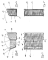
- Each transport carriage comprises a chassis 1 with four wheels 2.
- a pushing device 3 which comprises a handle bar 5 connecting two side supports 4 to one another.
- a platform 6 is pivotally articulated on the chassis 1 about a horizontal axis 7 extending transversely to the direction of travel. The pivotable articulation of the platform allows two transport trolleys to be stacked by sliding the platform of the rear transport trolley onto that of the front transport trolley and lifting it slightly.
- a container 8 designed as a basket is fastened between the two supports 4. This comprises a fixed section 9 and a position-changeable section 10.
- the position-changeable section 10 of the container 8 is around the fixed section 9 a horizontal axis 11 (see. Fig. 2 to 5) pivotally mounted.
- the position-changing section 10 of the container 8 of the rear transport carriage is pivoted upward about the axis 11 (arrow A). This brings the container from its first position (FIGS. 2 and 3) to its second position (FIGS. 4 and 5).
- the front side wall 12 of the container 8 in the direction of travel runs obliquely forward-upward in the direction of travel
- the front, upper edge 13 of the position-changing section 10 of the container 8 which runs transversely to the direction of travel first meets the rear wall 14 when a transport carriage is inserted into a stack the fixed section 9 of the container of the preceding trolley; this acts on the position-changing section 10 of the container a moment with respect to the pivot axis 11, so that when stacking two transport carriages, the position-changing section of the container of the rear transport carriage is automatically pivoted into the space-saving, upright position corresponding to the second position of the container (arrow A).
- FIG. 1 the structure of the container 8 provided in the transport vehicle according to FIG. 1 is shown in more detail.
- a stop 15 is provided on both sides of the position-changing section 10 of the container, which defines the position of the position-changing section 10 in the first position of the container by a vertical strut 16 of the fixed section 9 of the container embraces.
- the bottom 17 of the position-changing section 10 of the container assumes a vertical position; it forms the front side wall of the container in the second position.
- the actual opening opposite the bottom 17 of the position-changing section of the container, which in the first position of the container points upwards but in the second position backwards, is in the second position of the container through the rear side wall 14 of the fixed section 9 of the container covered.
- the front side wall 12 of the position-changing section 10 of the container is suspended in the region of the upper longitudinal edge 13, which runs transversely to the direction of travel, so that it can pivot about a horizontal axis 18. This enables the front side wall 12 to be pivoted into the interior of the position-changing section 10 of the container (arrow B). If the position-changing section 10 is pivoted about the axis 11 from the first position (FIGS. 2 and 3) to the second position (FIGS. 4 and 5) (arrow A), the front side wall 12 of the position-changing section 10 pivots due to the Gravity automatically into a position in which it is immediately adjacent to the rear wall 14 of the fixed portion 9 of the container.
- the space-saving collapsed container is easily accessible from above in its second position, because its opening pointing upward extends over the entire width and depth of the collapsed container. Also in the second position, the container is on all four sides through the bottom 17 and the side walls of the position-changing section 10 and the rear wall 14 of the fixed section 9 closed so that objects cannot fall out of it. If the container is brought from its second position into its first position (arrow C), the front side wall 12 of the position-changing section 10 of the container swings back automatically into its position shown in FIGS. 1, 2 and 3.
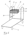
- the trolley shown in FIG. 6 is identical in its basic structure to the trolley according to German Offenlegungsschrift 34 05 154.
- the basket-like container 8 has a loop 19 on each of its two upper longitudinal edges running transversely to the direction of travel. These two loops 19 are guided on an axis 20 which extends horizontally in the direction of travel and one of the two brackets 21 is fastened between the two legs.
- the container 8 can be raised and brought into a space-saving vertical - shown in dash-dotted lines - second position (arrow D).
- German Offenlegungsschrift 34 05 154 the disclosure content of which is referred to in this respect.
- the side wall 22 of the container 8 which points upwards in the second position of the container, is pivotably suspended about a horizontal axis 23 running in the direction of travel. If the container is moved from its horizontal first position into the second position (shown in broken lines) (arrow D), the side wall 22 automatically pivots about the axis 23 into the interior of the container and in this way gives access to the container from above the second position free.
- the bottom of the The container opening opposite the container is closed in its second position by a wall 24 which is provided between the two legs of the bracket 21. That side wall 25 of the container, which lies opposite the pivotable side wall 22 and is adjacent to the bracket 21 in the first position of the container, forms the bottom thereof in the second position of the container.
Abstract
Description
Die vorliegende Erfindung betrifft einen Transportwagen, insbesondere Einkaufswagen, mit einem Behälter, von dem zumindest ein Abschnitt zwischen zwei Stellungen lageveränderbar ist, nämlich zwischen einer ersten Stellung, in der der Boden jenes lageveränderbaren Abschnitts des Behälters im wesentlichen horizontal verläuft, und einer zweiten Stellung, in der der Boden jenes lageveränderbaren Abschnitts des Behälters im wesentlichen vertikal verläuft, wobei diejenige Seitenwand des lageveränderbaren Abschnitts des Behälters, die in dessen Ruhelage nach oben weist, verschwenkbar aufgehängt ist.The present invention relates to a transport trolley, in particular a shopping trolley, having a container, at least a portion of which can be changed in position between two positions, namely between a first position in which the bottom of that adjustable portion of the container is essentially horizontal and a second position, in which the bottom of that position-changing section of the container runs essentially vertically, that side wall of the position-changing section of the container which points upwards in its rest position is pivotably suspended.
Aus dem französischen Patent 1 423 726 ist ein gattungsgemäßer Transportwagen bekannt. Dieser weist zwei übereinander angeordnete korbartige Warenbehälter auf. Von beiden Behältern ist jeweils ein in Fahrtrichtung vorderer Abschnitt um eine horizontale, quer zur Fahrtrichtung verlaufende Achse nach oben verschwenkbar. Sind die lageveränderbaren Abschnitte beider Behälter nach oben verschwenkt, können mehrere Transportwagen platzsparend ineinander gestapelt werden. In diesem Sinne nehmen die Behälter in ihrer ersten Stellung eine Gebrauchslage und in ihrer zweiten Stellung eine Ruhelage ein. Bei dem unteren, größeren Behälter ist die vordere Seitenwand in der Gebrauchslage nach unten abklappbar; auf diese Weise können die in diesem Behälter angesammelten Waren diesem im Kassenbereich leicht nach vorne entnommen werden. Eine Nutzung der Behälter zur Aufnahme von Gegenständen ist in deren zweiter Stellung (Ruhelage) nicht vorgesehen.A generic transport trolley is known from French patent 1,423,726. This has two basket-like goods containers arranged one above the other. From each of the two containers, a front section in the direction of travel can be pivoted upward about a horizontal axis running transversely to the direction of travel. If the position-changing sections of both containers are pivoted upwards, several transport trolleys can be stacked one inside the other to save space. In this sense, the containers assume a position of use in their first position and a rest position in their second position. In the lower, larger container, the front side wall can be folded down in the position of use; In this way, the goods accumulated in this container can be easily removed to the front in the checkout area. The containers are not intended to be used in their second position (rest position).
Ein ähnlicher Transportwagen, bei dem allerdings nur ein Behälter im vorstehenden Sinne vorgesehen ist, ist der US-A-4 560 180 entnehmbar. Auch hier nimmt der lageveränderbare Abschnitt des Behälters in seiner ersten Stellung eine Gebrauchslage und in seiner zweiten Stellung eine Ruhelage ein, in welcher ein Stapeln der Transportwagen, nicht jedoch eine Nutzung des Behälters zur Aufnahme von Gegenständen möglich ist. Die Stirnwand des Behälters, die dessen lageveränderbaren Abschnitt in der Gebrauchslage nach vorne abschließt, läßt sich nach vorn herunterklappen und in ihrer horizontalen Lage nach hinten unter den Boden des Behälters schieben, um ein Entnehmen der Waren aus dem Behälter zu erleichtern.A similar transport trolley, in which, however, only one container is provided in the above sense, can be found in US-A-4,560,180. Here, too, the position-changeable section of the container assumes a position of use in its first position and a rest position in its second position, in which stacking of the transport trolleys, but not using the container for receiving objects, is possible. The front wall of the container, which closes its position-changing section to the front in the position of use, can be folded down towards the front and, in its horizontal position, pushed back under the bottom of the container in order to facilitate removal of the goods from the container.
Die deutsche Offenlegungsschrift 34 05 154 offenbart einen Transportwagen, bei dem der Behälter, der als sich quer zur Fahrtrichtung erstreckender freitragender Korb gestaltet ist, aus einer waagerechten Gebrauchslage in eine nach unten gerichtete Ruhelage bewegbar ist. An den beiden oberen, der Öffnung benachbarten, quer zur Fahrtrichtung verlaufenden Längsrändern sind zwei Schlaufen vorgesehen, in denen eine feststehende, horizontal in Fahrtrichtung verlaufende Achse geführt ist. In der Ruhelage des Behälters weist dessen Öffnung seitwärts nach außen. Gegenstände können in dem in der Ruhelage befindlichen Behälter nicht aufgenommen werden, ohne daß die Gefahr besteht, daß sie seitlich herausfallen.German Offenlegungsschrift 34 05 154 discloses a transport trolley in which the container, which is designed as a self-supporting basket extending transversely to the direction of travel, can be moved from a horizontal position of use into a downward rest position. On the two upper longitudinal edges adjacent to the opening and extending transversely to the direction of travel, two loops are provided, in which a fixed axis running horizontally in the direction of travel is guided. In the rest position of the container, its opening points sideways outwards. Objects cannot be accommodated in the container in the rest position without the risk of them falling out to the side.
Durch offenkundige Vorgenutzung ist ein weiterer Transportwagen bekanntgeworden, dessen korbartiger Behälter als ganzes aus einer ersten Stellung mit horizontalem Boden in eine zweite Stellung mit vertikalem Boden verschwenkbar ist. Die dem Boden des Behälters gegen-überliegende Öffnung weist in der zweiten Stellung nach hinten; sie ist dann in ihrem unteren Bereich durch ein Klappgitter teilweise verschließbar. Der Behälter ist auf diese Weise in beiden Stellungen zur Aufnahme von Gegenständen nutzbar, wobei in der zweiten, platzsparenden Stellung eine deutlich geringere Grundfläche zum Abstellen von Gegenständen (z. B. stehende Flaschen) zur Verfügung steht als in der ersten Stellung. Allerdings ist das Be- und Entladen des Behälters in der zweiten Stellung schwierig, wenn das Klappgitter zu groß ist; umgekehrt besteht bei zu kleinem Klappgitter die Gefahr, daß Gegenstände aus dem Behälter nach hinten herausfallen.Through obvious prior use, another transport trolley has become known, the basket-like container of which can be pivoted as a whole from a first position with a horizontal bottom to a second position with a vertical bottom. The one opposite the bottom of the container In the second position, the opening points to the rear; it can then be partially closed in its lower area by a folding grille. In this way, the container can be used in both positions to hold objects, with the second, space-saving position providing a significantly smaller footprint for storing objects (e.g. standing bottles) than in the first position. However, loading and unloading the container in the second position is difficult if the folding grille is too large; conversely, if the folding grille is too small, there is a risk of objects falling out of the container to the rear.
Aus der europäischen Patentanmeldung 337 043 ist ein weiterer Transportwagen bekannt, bei dem der Behälter als ganzes aus einer im wesentlichen horizontalen Gebrauchslage in eine im wesentlichen vertikale Ruhelage bewegbar ist. Hierzu sind zu beiden Seiten des Transportwagens Führungen vorgesehen, in denen hintenunten am Behälter vorgesehene Vorsprünge geführt werden. In der Ruhelage des Behälters weist dessen Öffnung nach hinten. Die Transportwagen sind nicht nur dann stapelbar, wenn sich die Behälter in ihrer Ruhelage befinden; die schwenkbare Aufhängung der Rückwand des Behälters gestattet - in von üblichen Einkaufswagen her bekannter Weise - das Stapeln mehrerer Transportwagen auch dann, wenn die Behälter sich in Gebrauchslage befinden, indem der Behälter des jeweils hinteren Transportwagens von hinten her in den Behälter des jeweils vorderen Transportwagens eingeschoben wird. In der Ruhelage des Behälters können in diesem Gegenstände nicht transportiert werden.Another transport trolley is known from European patent application 337 043, in which the container as a whole can be moved from an essentially horizontal position of use to an essentially vertical position of rest. For this purpose, guides are provided on both sides of the transport carriage, in which projections provided on the bottom rear of the container are guided. In the rest position of the container, its opening points to the rear. The transport trolleys are not only stackable when the containers are in their rest position; the pivotable suspension of the rear wall of the container allows - in a manner known from conventional shopping trolleys - the stacking of several transport trolleys even when the containers are in the position of use by inserting the container of the rear transport trolley from behind into the container of the front transport trolley becomes. Objects cannot be transported in this position when the container is at rest.
Durch offenkundige Vorbenutzung sowie die deutsche Patentschrift 34 45 685 ist schließlich ein Möbeltransportwagen bekanntgeworden, dessen Behälter als geteilter, aus zwei Abschnitten bestehender Klappkorb ausgebildet ist. In der Gebrauchslage erstreckt sich der Behälter quer zur Fahrtrichtung zwischen zwei rückseitig am Transportwagen angeordneten Bügeln. Dabei ist ein Abschnitt des Behälters fest an dem entsprechenden Bügel angeordnet; ein lageveränderbarer Abschnitt des Behälters ist mit dem feststehenden Abschnitt um eine horizontale, in Fahrtrichtung verlaufende Achse schwenkbar verbunden. Sollen sperrige Güter transportiert werden, wird der lageveränderbare Abschnitt des Behälters aus seiner ersten Stellung nach oben in eine zweite Stellung geklappt. In dieser Ruhestellung umschließt der lageveränderbare Abschnitt im wesentlichen den feststehenden Abschnitt des Behälters. Das Innere des Behälters ist in dessen Ruhelage nur durch eine kleine Öffnung von oben her zugänglich; eine Nutzung des Behälters zum Transport von Gegenständen scheidet daher praktisch aus, wenn sich der lageveränderbare Abschnitt des Behälters in seiner zweiten Stellung befindet.Through obvious prior use and German patent 34 45 685, a furniture transport trolley has finally become known, the container of which is designed as a split folding basket consisting of two sections. In the position of use, the container extends transversely to the direction of travel between two brackets arranged on the rear of the transport trolley. A section of the container is firmly arranged on the corresponding bracket; a position-changing section of the container is pivotally connected to the fixed section about a horizontal axis running in the direction of travel. If bulky goods are to be transported, the position-changing section of the container is folded up from its first position into a second position. In this rest position, the position-changeable section essentially encloses the fixed section of the container. The interior of the container is only accessible from above through a small opening in its rest position; use of the container for the transport of objects is therefore practically ruled out when the position-changing section of the container is in its second position.
Bei allen vorstehend angegebenen Transportwagen ist es von Nachteil, daß der Behälter dann, wenn sich sein lageveränderbarer Abschnitt in seiner (platzsparenden) zweiten Stellung befindet, entweder überhaupt nicht oder aber nur sehr eingeschränkt nutzbar ist, weil entweder kein Zugang zum Inneren des Behälters besteht, oder aber die Öffnung zu dem Behälter entweder klein ist oder nur von der Seite her Zugang zum Inneren des Behälters gewährt.In all of the above-mentioned transport vehicles, it is disadvantageous that the container, when its position-changing section is in its (space-saving) second position, can either not be used at all or can only be used to a very limited extent, because either there is no access to the interior of the container, or the opening to the container is either small or only allows access to the inside of the container from the side.
Der vorliegenden Erfindung liegt die Aufgabe zugrunde, einen gattungsgemäßen Transportwagen zu schaffen, bei dem der Behälter auch dann ohne Schwierigkeiten nutzbar ist, wenn sich sein lageveränderbarer Abschnitt in seiner (platzsparenden) zweiten Stellung befindet. Insbesondere soll der Behälter auch in diesem Falle durch eine möglichst große Öffnung von oben her bequem zugänglich sein.The present invention has for its object to provide a generic transport trolley in which the container can be used without difficulty even when its position-changing section is in its (space-saving) second position. In particular, the container should also be easily accessible from above through the largest possible opening.
Gemäß der vorliegenden Erfindung wird diese Aufgabe bei einem gattungsgemäßen Transportwagen dadurch gelöst, daß die verschwenkbar aufgehängte Seitenwand des Behälters, wenn dessen lageveränderbarer Abschnitt sich in der zweiten Stellung befindet, nach unten in das Innere des Behälters eingeschwenkt ist und einen nach oben weisenden Zugang zum Inneren des Behälters freigibt. Gemäß der Erfindung ist somit diejenige Seitenwand des lageveränderbaren Abschnitts des Behälters, die dann, wenn dieser Abschnitt seine (platzsparende) zweite Stellung einnimmt, nach oben weist, in der Weise verschwenkbar aufgehängt, daß sie als ganzes einschwenkt, wenn der lageveränderbare Abschnitt des Behälters von seiner ersten in seine zweite Stellung gebracht wird. Hierdurch entsteht eine nach oben weisende Öffnung des Behälters in seiner zweiten Stellung; d. h. der Behälter ist auch in dieser Stellung von oben her bequem zugänglich. Insbesondere kann dabei die verschwenkbar aufgehängte Seitenwand infolge der Schwerkraft selbsttätig nach unten in das Innere des Behälters hineinschwenken, wenn dessen lageveränderbarer Abschnitt in die zweite Stellung gebracht wird. Bei dem erfindungsgemäßen Transportwagen ist der Behälter somit unabhängig davon, ob er seine erste oder seine (platzsparende) zweite Stellung einnimmt, stets von oben her frei zugänglich. Er kann bequem von oben her beladen und nach oben entladen werden.According to the present invention, this object is achieved in a generic transport trolley in that the pivotally suspended side wall of the container, when its position-changing section is in the second position, is pivoted downward into the interior of the container and an upward-facing access to the interior releases the container. According to the invention, that side wall of the position-changing section of the container, which, when this section assumes its (space-saving) second position, points upwards, is pivotably suspended in such a way that it pivots in as a whole when the position-changing section of the container from his first is brought into his second position. This creates an upward opening of the container in its second position; ie the container is also easily accessible from above in this position. In particular, the pivotably suspended side wall can automatically pivot downward into the interior of the container as a result of gravity when its position-changing section is brought into the second position. In the transport trolley according to the invention, the container is therefore always freely accessible from above, regardless of whether it takes its first or its (space-saving) second position. He can can be conveniently loaded from above and unloaded upwards.
Bei dem erfindungsgemäßen Transportwagen ist die in der zweiten Stellung des Behälters zur Seite weisende, dem Boden gegenüberliegende eigentliche Öffnung des lageveränderbaren Abschnitts des Behälters zweckmäßigerweise durch eine feststehende Wand zumindest teilweise abgeschlossen. Hierdurch wird verhindert, daß in dem Behälter in seiner zweiten Stellung aufgenommene Gegenstände durch die zur Seite weisende eigentliche Öffnung des lageveränderbaren Abschnitts des Behälters herausfallen können. Die feststehende Wand kann dabei entweder ein Teil des feststehenden Abschnitts des Behälters sein, insbesondere eine von dessen Seitenwänden. Als die eigentliche Öffnung des lageveränderbaren Abschnitts des Behälters in dessen zweiter Stellung abschließende Wand kommen jedoch in gleicher Weise gesonderte Bauelemente (z. B. ein Blech oder ein Gitter) in Betracht, die am Transportwagen fest angeordnet sind.In the transport trolley according to the invention, the actual opening of the position-changing section of the container facing away from the floor in the second position of the container is expediently at least partially closed off by a fixed wall. This prevents objects accommodated in the container in its second position from falling out through the actual opening to the side of the position-changing section of the container. The fixed wall can either be part of the fixed section of the container, in particular one of its side walls. However, as the actual opening of the position-changing section of the container in its second position, the wall is closed in the same way separate components (z. B. a sheet or a grid), which are fixed to the trolley.
Die Erfindung ist sowohl für solche Transportwagen anwendbar, bei denen der Behälter als ganzes lageveränderbar aufgehängt ist, wie dies beispielsweise für den Transportwagen gemäß der deutschen Offenlegungsschrift 34 05 154 zutrifft. In gleicher Weise ist die vorliegende Erfindung anwendbar auf Transportwagen, bei denen nur ein Abschnitt des Behälters lageveränderbar, ein weiterer Abschnitt hingegen feststehend ist, wie dies beispielsweise für den durch die DE-PS 34 45 685 sowie durch offenkundige Vorbenutzung bekanntgewordenen Möbeltransportwagen oder den Transportwagen gemäß der FR-PS 1 423 726 zutrifft. Bei einer besonders bevorzugten Weiterbildung des erfindungsgemäßen Transportwagens mit der zuletzt genannten Ausbildung des Behälters taucht in der zweiten Stellung der lageveränderbare Abschnitt des Behälters in den feststehenden ein oder umgekehrt. Bei einer derartigen Ausgestaltung des erfindungsgemäßen Transportwagens beansprucht der Behälter, wenn er seine zweite Stellung einnimmt, nur minimalen Platz.The invention can be used both for transport trolleys in which the container is suspended as a whole in such a way that it can be changed in position, as is the case, for example, for the transport trolley according to German Offenlegungsschrift 34 05 154. In the same way, the present invention is applicable to transport trolleys in which only one section of the container can be changed in position, but a further section is fixed, as is the case, for example, for the furniture transport trolley which has become known through DE-PS 34 45 685 and for prior use or the transport trolley according to FR-PS 1 423 726 applies. In a particularly preferred development of the trolley according to the invention with the last-mentioned design of the container, the position-changing portion of the container is immersed in the fixed position in the second position or vice versa. In such a configuration of the transport trolley according to the invention, the container occupies only minimal space when it occupies its second position.
Eine bevorzugte Weiterbildung der Erfindung ist dadurch gekennzeichnet, daß der als ganzes lageveränderbare Behälter bzw. dessen lageveränderbarer Abschnitt um eine horizontal, quer zur Fahrtrichtung verlaufende Achse verschwenkbar aufgehängt ist. Dieses Merkmal gestattet auf besonders einfache Weise ein selbsttätiges Einschwenken des Behälters aus seiner ersten Stellung in seine platzsparende zweite Stellung, wenn zwei Transportwagen gestapelt werden. Besonders begünstigt wird das selbsttätige Einschwenken des lageveränderbaren Abschnitts des Behälters durch eine schräg nach oben-vorne weisende Ausrichtung der in Fahrtrichtung weisenden Seitenwand des lageveränderbaren Abschnitts des Behälters. Denn bei der zuletzt genannten Weiterbildung des erfindungsgemäßen Transportwagens trifft der lageveränderbare Abschnitt des Behälters mit seiner vorderen, oberen, quer zur Fahrtrichtung verlaufenden Kante beim Stapeln zweier Transportwagen auf ein Bauteil des jeweils vorderen Transportwagens, wodurch ein den Behälter kippendes Moment erzeugt wird.A preferred development of the invention is characterized in that the container which can be changed as a whole or its section which can be changed in position is suspended so as to be pivotable about an axis which runs horizontally and transversely to the direction of travel. This feature allows, in a particularly simple manner, the container to be swiveled automatically from its first position into its space-saving second position when two transport carriages are stacked. The automatic pivoting of the position-changing section of the container is particularly favored by an obliquely upward-forward orientation of the side wall of the position-changing section of the container pointing in the direction of travel. Because in the last-mentioned development of the transport trolley according to the invention, the position-changing section of the container meets with its front, upper, transverse edge to the direction of travel when stacking two transport trolleys on a component of the respective front transport trolley, thereby generating a moment of tilting the container.
Im folgenden wird die Erfindung anhand der in der Zeichnung dargestellten Ausführungsbeispiele näher erläutert. Es zeigt
- Fig. 1
- in Seitenansicht zwei ineinander gestapelte Transportwagen gemäß der Erfindung, wobei sich der Behälter des vorderen Transportwagens in seiner ersten Stellung und der Behälter des hinteren Transportwagens in seiner zweiten Stellung befindet,
- Fig. 2 und 3
- in Seitenansicht bzw. Draufsicht den Behälter des Transportwagens gemäß Fig. 1 in seiner ersten Stellung,
- Fig. 4 und 5
- in Seitenansicht bzw. Draufsicht den Behälter des Transportwagens gemäß Fig. 1 in seiner zweiten Stellung und
- Fig. 6
- in perspektivischer Ansicht ein weitere Ausführungsbeispiel des erfindungsgemäßen Transportwagens.
- Fig. 1
- in side view two stacked trolleys according to the invention, the container of the front transport carriage being in its first position and the container of the rear transport carriage being in its second position,
- 2 and 3
- 1 in its first position, in side view or plan view, the container of the transport vehicle according to FIG. 1,
- 4 and 5
- in side view or plan view of the container of the trolley according to FIG. 1 in its second position and
- Fig. 6
- a perspective view of another embodiment of the trolley according to the invention.
Der grundsätzliche Aufbau der in Fig. 1 dargestellten Transportwagen ist allgemein bekannt. Jeder Transportwagen umfaßt ein Fahrgestell 1 mit vier Rädern 2. Rückseitig an dem Fahrgestell 1 ist jeweils eine Schiebeeinrichtung 3 vorgesehen, die eine zwei seitliche Träger 4 miteinander verbindende Griffstange 5 umfaßt. An dem Fahrgestell 1 ist eine Plattform 6 um eine horizontale, quer zur Fahrtrichtung verlaufende Achse 7 verschwenkbar angelenkt. Die verschwenkbare Anlenkung der Plattform gestattet das Stapeln zweier Transportwagen, indem die Plattform des jeweils hinteren Transportwagens auf diejenige des jeweils vorderen Transportwagens aufgleitet und dabei geringfügig angehoben wird.The basic structure of the trolley shown in Fig. 1 is generally known. Each transport carriage comprises a chassis 1 with four
Zwischen den beiden Trägern 4 ist ein als Korb ausgebildeter Behälter 8 befestigt. Dieser umfaßt einen feststehenden Abschnitt 9 und einen lageveränderbaren Abschnitt 10. Der lageveränderbare Abschnitt 10 des Behälters 8 ist an dem feststehenden Abschnitt 9 um eine horizontale Achse 11 (vgl. Fig. 2 bis 5) verschwenkbar gelagert. Beim Stapeln zweier Transportwagen wird der lageveränderbare Abschnitt 10 des Behälters 8 des hinteren Transportwagens um die Achse 11 nach oben geschwenkt (Pfeil A). Hierdurch wird der Behälter von seiner ersten Stellung (Fig. 2 und 3) in seine zweite Stellung (Fig. 4 und 5) gebracht. Indem die in Fahrtrichtung vordere Seitenwand 12 des Behälters 8 in Fahrtrichtung schräg nach vorne-oben verläuft, trifft die vordere, obere, quer zur Fahrtrichtung verlaufende Kante 13 des lageveränderbaren Abschnitts 10 des Behälters 8 beim Einschieben eines Transportwagens in einen Stapel zuerst auf die Rückwand 14 des feststehenden Abschnitts 9 des Behälters des vorausbefindlichen Transportwagens; hierdurch wirkt auf den lageveränderbaren Abschnitt 10 des Behälters ein Moment bezüglich der Schwenkachse 11, so daß beim Stapeln zweier Transportwagen der lageveränderbare Abschnitt des Behälters des hinteren Transportwagens selbsttätig in die platzsparende, der zweiten Stellung des Behälters entsprechende aufrechte Position verschwenkt wird (Pfeil A).A
In den Fig. 2 bis 5 ist der Aufbau des bei den Transportwagen gemäß Fig. 1 vorgesehenen Behälters 8 detaillierter dargestellt. Insbesondere ist in diesen Figuren erkennbar, daß an dem lageveränderbaren Abschnitt 10 des Behälters beidseitig je ein Anschlag 15 vorgesehen ist, der die Stellung des lageveränderbaren Abschnitts 10 in der ersten Stellung des Behälters definiert, indem er eine vertikale Strebe 16 des feststehenden Abschnitts 9 des Behälters umgreift.2 to 5, the structure of the
Wird der lageveränderbare Abschnitt 10 des Behälters um die Achse 11 nach oben geschwenkt (Pfeil A), so daß der Behälter aus seiner ersten Stellung (Fig. 2 und 3) in seine zweite Stellung (Fig. 4 und 5) gebracht wird, nimmt der Boden 17 des lageveränderbaren Abschnitts 10 des Behälters eine vertikale Lage ein; er bildet in der zweiten Stellung des Behälters dessen vordere Seitenwand. Die dem Boden 17 des lageveränderbaren Abschnitts des Behälters gegenüberliegende eigentliche Öffnung, die in der ersten Stellung des Behälters nach oben, in der zweiten Stellung hingegen nach hinten weist, ist in der zweiten Stellung des Behälters durch die hintere Seitenwand 14 des feststehenden Abschnitts 9 des Behälters abgedeckt.If the position-changing
Die vordere Seitenwand 12 des lageveränderbaren Abschnitts 10 des Behälter ist im Bereich der oberen, quer zur Fahrtrichtung verlaufenden Längskante 13 um eine horizontale Achse 18 verschwenkbar aufgehängt. Dies ermöglicht ein Einschwenken der vorderen Seitenwand 12 in das Innere des lageveränderbaren Abschnitts 10 des Behälters (Pfeil B). Wird der lageveränderbare Abschnitt 10 um die Achse 11 herum aus der ersten Stellung (Fig. 2 und 3) in die zweite Stellung (Fig. 4 und 5) verschwenkt (Pfeil A), verschwenkt sich die vordere Seitenwand 12 des lageveränderbaren Abschnitts 10 aufgrund der Schwerkraft selbsttätig in eine Stellung, in der sie unmittelbar benachbart der Rückwand 14 des feststehenden Abschnitts 9 des Behälters liegt. Auf diese Weise ist auch der raumsparend zusammengeklappte Behälter in seiner zweiten Stellung bequem von oben her zugänglich, denn seine nach oben weisende Öffnung erstreckt sich über die gesamte Breite und Tiefe des zusammengeklappten Behälters. Auch in der zweiten Stellung ist der Behälter an allen vier Seiten durch den Boden 17 und die Seitenwände des lageveränderbaren Abschnitts 10 sowie die Rückwand 14 des feststehenden Abschnitts 9 hoch geschlossen, so daß Gegenstände aus ihm nicht herausfallen können. Wird der Behälter aus seiner zweiten Stellung in seine erste Stellung gebracht (Pfeil C), verschwenkt sich die vordere Seitenwand 12 des lageveränderbaren Abschnitts 10 des Behälters wieder selbsttätig in ihre in den Fig. 1, 2 und 3 dargestellte Stellung.The
Der in Fig. 6 dargestellte Transportwagen ist von seinem grundsätzlichen Aufbau her identisch mit dem Transportwagen gemäß der deutschen Offenlegungsschrift 34 05 154. Der korbartige Behälter 8 weist an seinen beiden oberen, quer zur Fahrtrichtung verlaufenden Längskanten je eine Schleife 19 auf. Diese beiden Schleifen 19 sind an einer Achse 20 geführt, die sich horizontal in Fahrtrichtung erstreckt und zwischen den beiden Schenkeln eines der beiden Bügel 21 befestigt ist. Der Behälter 8 kann angehoben und in eine platzsparende vertikale - strichpunktiert dargestellte - zweite Stellung gebracht werden (Pfeil D). Im Hinblick auf weitergehende Details wird auf die deutsche Offenlegungsschrift 34 05 154 verwiesen, auf deren Offenbarungsgehalt insoweit Bezug genommen wird.The trolley shown in FIG. 6 is identical in its basic structure to the trolley according to German Offenlegungsschrift 34 05 154. The basket-
Die Seitenwand 22 des Behälters 8, die in der zweiten Stellung des Behälter nach oben weist, ist um eine horizontale, in Fahrtrichtung verlaufende Achse 23 verschwenkbar aufgehängt. Wird der Behälter aus seiner horizontalen ersten Stellung in die - strichpunktiert dargestellte - zweite Stellung bewegt (Pfeil D), verschwenkt sich die Seitenwand 22 selbsttätig um die Achse 23 in das Innere des Behälters und gibt auf diese Weise einen Zugang von oben zu dem Behälter in der zweiten Stellung frei. Die eigentliche, dem Boden des Behälters gegenüberliegende Öffnung des Behälters ist in dessen zweiter Stellung von einer Wand 24 verschlossen, die zwischen den beiden Schenkeln des Bügels 21 vorgesehen ist. Diejenige Seitenwand 25 des Behälters, die der verschwenkbaren Seitenwand 22 gegenüberliegt und in der ersten Stellung des Behälters dem Bügel 21 benachbart ist, bildet in der zweiten Stellung des Behälters dessen Boden.The
Auch bei der in Fig. 6 dargestellten Ausführungsform des erfindungsgemäßen Transportwagens ergibt sich somit in der platzsparenden zweiten Stellung des Behälters die Möglichkeit, diesen bequem durch eine Öffnung von maximaler Größe von oben her zu beladen, wobei keine Gefahr gesteht, daß die in dem Behälter aufgenommenen Gegenstände aus diesem herausfallen.Also in the embodiment of the trolley according to the invention shown in FIG. 6, in the space-saving second position of the container, there is the possibility of loading it conveniently from above through an opening of maximum size, with no risk that the containers accommodated in the container Objects fall out of it.
Claims (7)
dadurch gekennzeichnet,
daß die verschwenkbar aufgehängte Seitenwand (12, 22) des Behälters, wenn dessen lageveränderbarer Abschnitt (10) sich in der zweiten Stellung befindet, nach unten in das Innere des Behälters (8) eingeschwenkt ist und einen nach oben weisenden Zugang zum Inneren des Behälters freigibt.Transport trolley, in particular a shopping trolley, with a container (8), of which at least one section (10) can be changed in position between two positions, namely between a first position in which the bottom (17) of that adjustable section (10) of the container (8) is substantially horizontal, and a second position in which the bottom of that positionally variable portion of the container is substantially vertical, the side wall (12, 22) of the positionally variable portion (10) of the container (8) being in its second position points above, is pivotally suspended,
characterized,
that the pivotally suspended side wall (12, 22) of the container, when its position-changing section (10) is in the second position, is pivoted downward into the interior of the container (8) and releases an upward-facing access to the interior of the container .
dadurch gekennzeichnet,
daß die verschwenkbar aufgehängte Seitenwand (12, 22) des Behälters in dessen zweiter Stellung parallel zu dessen Boden (17) verläuft.Transport trolley according to claim 1,
characterized,
that the pivotally suspended side wall (12, 22) of the container in its second position runs parallel to the bottom (17) thereof.
dadurch gekennzeichnet,
daß der Behälter (8) einen feststehenden Abschnitt (9) und einen lageveränderbaren Abschnitt (10) umfaßt, wobei in der zweiten Stellung der lageveränderbare Abschnitt in den feststehenden Abschnitt eintaucht.Transport trolley according to claim 1,
characterized,
that the container (8) comprises a fixed section (9) and a position-changing section (10), the position-changing section being immersed in the fixed section in the second position.
dadurch gekennzeichnet,
daß der lageveränderbare Abschnitt (10) des Behälters (8) um eine horizontale Achse (11) verschwenkbar an dem feststehenden Abschnitt des Behälters aufgehängt ist.Transport trolley according to claim 3,
characterized,
that the position-changing section (10) of the container (8) about a horizontal axis (11) is suspended on the fixed section of the container.
dadurch gekennzeichnet,
daß der Behälter (8) als ganzes lageveränderbar aufgehängt ist und daß eine feststehende, im wesentlichen vertikal verlaufende Wand (24) vorgesehen ist, die in der zweiten Stellung des Behälters (8) dessen dem Boden (17) gegenüberliegende eigentliche Öffnung zumindest teilweise verschließt.Transport trolley according to claim 1,
characterized,
that the container (8) is suspended as a whole, and that a fixed, substantially vertical wall (24) is provided, which in the second position of the container (8) at least partially closes the actual opening opposite the bottom (17).
dadurch gekennzeichnet,
daß der als ganzes lageveränderbare Behälter (8) bzw. dessen lageveränderbarer Abschnitt um eine horizontal, quer zur Fahrtrichtung verlaufende Achse (11) verschwenkbar aufgehängt ist.Transport trolley according to claim 1,
characterized,
that the entire position-changeable container (8) or its position-changeable section is suspended so as to be pivotable about a horizontal axis (11) running transversely to the direction of travel.
dadurch gekennzeichnet,
daß die in der ersten Stellung des Behälters in Fahrtrichtung des Transportwagens vorne angeordnete Seitenwand (12) des Behälters schräg nach vorne-oben geneigt verläuft.Transport trolley according to claim 6,
characterized,
that the side wall (12) of the container, which is arranged at the front in the direction of travel of the transport carriage in the first position of the container, is inclined obliquely towards the front and up.
Applications Claiming Priority (2)
| Application Number | Priority Date | Filing Date | Title |
|---|---|---|---|
| DE4417418A DE4417418C2 (en) | 1994-05-18 | 1994-05-18 | Dolly |
| DE4417418 | 1994-05-18 |
Publications (3)
| Publication Number | Publication Date |
|---|---|
| EP0683083A2 true EP0683083A2 (en) | 1995-11-22 |
| EP0683083A3 EP0683083A3 (en) | 1996-11-20 |
| EP0683083B1 EP0683083B1 (en) | 1999-03-10 |
Family
ID=6518390
Family Applications (1)
| Application Number | Title | Priority Date | Filing Date |
|---|---|---|---|
| EP95106969A Expired - Lifetime EP0683083B1 (en) | 1994-05-18 | 1995-05-09 | Transport trolley |
Country Status (4)
| Country | Link |
|---|---|
| EP (1) | EP0683083B1 (en) |
| AT (1) | ATE177382T1 (en) |
| DE (2) | DE4417418C2 (en) |
| ES (1) | ES2131724T3 (en) |
Families Citing this family (9)
| Publication number | Priority date | Publication date | Assignee | Title |
|---|---|---|---|---|
| DE29600565U1 (en) * | 1996-01-15 | 1996-03-07 | Wanzl Metallwarenfabrik Kg | Transport trolley that can be moved by hand |
| DE19920185C1 (en) * | 1999-05-03 | 2000-07-13 | Siegel Geb Gmbh Co Kg | Shopping trolley has an edging section for the basket to extend the side walls selectively forwards or upwards according to the amount of shopping to be carried |
| DE10162007B4 (en) * | 2001-12-18 | 2004-07-01 | Brüder Siegel GmbH & Co KG Draht- und Metallwarenfabrik | Manually operated trolley |
| DE10224840A1 (en) * | 2002-06-05 | 2003-12-24 | Wanzl Metallwarenfabrik Kg | Transport trolley that can be moved by hand |
| DE10305194A1 (en) | 2003-01-07 | 2004-07-15 | Brüder Siegel GmbH & Co KG Draht- und Metallwarenfabrik | Stackable trolley, especially shopping trolley, has deflection disk under lower goods support and above front rollers with openings that rear roller carriers of preceding trolley can enter when stacking |
| DE102007060983A1 (en) | 2007-12-14 | 2009-06-18 | Wanzl Metallwarenfabrik Gmbh | Hand movable trolley for transporting e.g. goods, has basket formed of set of side walls and arranged above platform, where one sidewall is formed of exchangeably arranged advertising board with clip region |
| DE102011010154A1 (en) * | 2011-02-02 | 2012-08-02 | Wanzl Metallwarenfabrik Gmbh | Stackable transport carriage for use in self-service-store to transport heavy objects, has goods tray formed with two platforms whose tray surface is extended if necessary, and supplementary and layer-variable tray fixed at one platform |
| DE202013100947U1 (en) * | 2013-03-05 | 2014-06-06 | J. D. Geck Gmbh | Foldable shopping cart attachment for attaching to a stackable shopping cart basket and stackable shopping cart basket |
| EP3947104B1 (en) * | 2019-04-03 | 2024-02-21 | Knap | Trolley for supporting and weighing a container |
Citations (5)
| Publication number | Priority date | Publication date | Assignee | Title |
|---|---|---|---|---|
| DE340515C (en) | 1921-09-14 | Thomas Rozankovich | Wheel with leaf spring spokes | |
| FR1423726A (en) | 1964-09-23 | 1966-01-07 | Union Steel Prod Co | Store stroller |
| US4560180A (en) | 1984-06-11 | 1985-12-24 | Whittar Industries, Ltd. | Shopping cart |
| DE3445685A1 (en) | 1984-02-14 | 1986-06-19 | Rudolf Wanzl Kg, 8874 Leipheim | Manually movable transport cart |
| EP0337043A1 (en) | 1988-04-06 | 1989-10-18 | Ateliers Reunis Caddie | Shopping cart with pivotable basket |
Family Cites Families (5)
| Publication number | Priority date | Publication date | Assignee | Title |
|---|---|---|---|---|
| US3245498A (en) * | 1963-09-24 | 1966-04-12 | Stanley | Supermarket cart |
| DE3402944A1 (en) * | 1984-01-28 | 1985-08-08 | Rudolf Wanzl Kg, 8874 Leipheim | Arrangement of two racks on two upright supports |
| DE3405154A1 (en) * | 1984-02-14 | 1985-08-22 | Rudolf Wanzl Kg, 8874 Leipheim | Cart |
| DE8904507U1 (en) * | 1989-04-11 | 1989-11-09 | Wanzl Gmbh & Co Entwicklungs Kg, 8874 Leipheim, De | |
| DE8908242U1 (en) * | 1989-07-06 | 1990-01-04 | Wanzl Gmbh & Co Entwicklungs Kg, 8874 Leipheim, De |
-
1994
- 1994-05-18 DE DE4417418A patent/DE4417418C2/en not_active Expired - Fee Related
-
1995
- 1995-05-09 ES ES95106969T patent/ES2131724T3/en not_active Expired - Lifetime
- 1995-05-09 AT AT95106969T patent/ATE177382T1/en not_active IP Right Cessation
- 1995-05-09 EP EP95106969A patent/EP0683083B1/en not_active Expired - Lifetime
- 1995-05-09 DE DE59505240T patent/DE59505240D1/en not_active Expired - Lifetime
Patent Citations (5)
| Publication number | Priority date | Publication date | Assignee | Title |
|---|---|---|---|---|
| DE340515C (en) | 1921-09-14 | Thomas Rozankovich | Wheel with leaf spring spokes | |
| FR1423726A (en) | 1964-09-23 | 1966-01-07 | Union Steel Prod Co | Store stroller |
| DE3445685A1 (en) | 1984-02-14 | 1986-06-19 | Rudolf Wanzl Kg, 8874 Leipheim | Manually movable transport cart |
| US4560180A (en) | 1984-06-11 | 1985-12-24 | Whittar Industries, Ltd. | Shopping cart |
| EP0337043A1 (en) | 1988-04-06 | 1989-10-18 | Ateliers Reunis Caddie | Shopping cart with pivotable basket |
Also Published As
| Publication number | Publication date |
|---|---|
| ES2131724T3 (en) | 1999-08-01 |
| EP0683083A3 (en) | 1996-11-20 |
| DE4417418A1 (en) | 1995-06-01 |
| DE4417418C2 (en) | 1998-03-12 |
| ATE177382T1 (en) | 1999-03-15 |
| EP0683083B1 (en) | 1999-03-10 |
| DE59505240D1 (en) | 1999-04-15 |
Similar Documents
| Publication | Publication Date | Title |
|---|---|---|
| DE2924658A1 (en) | ROLLER CART | |
| EP0141398B1 (en) | Nestable shopping trolley | |
| EP0683083B1 (en) | Transport trolley | |
| DE8500639U1 (en) | Shopping carts for self-service shops with a storage device for boxes or the like. | |
| DE3231323A1 (en) | Shopping trolley for use in conjunction with motor vehicles | |
| DE102008031541A1 (en) | Trolley i.e. shopping trolley, for use by consumer e.g. during transportation of article i.e. goods, in supermarket, has transportation basket i.e. folding box, that is fixed on foldable chassis in foldable and detachable manner | |
| DE8508238U1 (en) | Stackable shopping cart | |
| EP0254210B2 (en) | Nestable shopping trolley | |
| DE8136236U1 (en) | STACKABLE SHOPPING CART | |
| EP0672569B1 (en) | Shopping trolley | |
| EP0609663B1 (en) | Shopping trolley | |
| EP0751057B1 (en) | Nestable shopping trolley | |
| DE3444278C2 (en) | Stackable shopping cart | |
| WO2001000475A1 (en) | Stackable transport cart | |
| EP0905004B1 (en) | Nestable shopping trolley | |
| WO2000034101A2 (en) | Shopping cart | |
| DE2739291A1 (en) | TRANSPORT CART OR TROLLEY | |
| EP0798193B1 (en) | Nestable shopping trolley | |
| WO2005030556A2 (en) | Shopping trolley | |
| DE8331746U1 (en) | STACKABLE SHOPPING CART | |
| DE3233291C2 (en) | ||
| EP0738645B1 (en) | Nestable shopping trolley | |
| EP0685378B1 (en) | Nestable shopping trolley | |
| EP0676323B1 (en) | Nestable shopping trolley | |
| EP1093988A1 (en) | Transport trolley |
Legal Events
| Date | Code | Title | Description |
|---|---|---|---|
| PUAI | Public reference made under article 153(3) epc to a published international application that has entered the european phase |
Free format text: ORIGINAL CODE: 0009012 |
|
| AK | Designated contracting states |
Kind code of ref document: A2 Designated state(s): AT BE CH DE ES FR GB IT LI LU NL |
|
| PUAL | Search report despatched |
Free format text: ORIGINAL CODE: 0009013 |
|
| AK | Designated contracting states |
Kind code of ref document: A3 Designated state(s): AT BE CH DE ES FR GB IT LI LU NL |
|
| 17P | Request for examination filed |
Effective date: 19961015 |
|
| 17Q | First examination report despatched |
Effective date: 19980114 |
|
| GRAG | Despatch of communication of intention to grant |
Free format text: ORIGINAL CODE: EPIDOS AGRA |
|
| GRAG | Despatch of communication of intention to grant |
Free format text: ORIGINAL CODE: EPIDOS AGRA |
|
| GRAH | Despatch of communication of intention to grant a patent |
Free format text: ORIGINAL CODE: EPIDOS IGRA |
|
| GRAH | Despatch of communication of intention to grant a patent |
Free format text: ORIGINAL CODE: EPIDOS IGRA |
|
| GRAA | (expected) grant |
Free format text: ORIGINAL CODE: 0009210 |
|
| AK | Designated contracting states |
Kind code of ref document: B1 Designated state(s): AT BE CH DE ES FR GB IT LI LU NL |
|
| REF | Corresponds to: |
Ref document number: 177382 Country of ref document: AT Date of ref document: 19990315 Kind code of ref document: T |
|
| REG | Reference to a national code |
Ref country code: CH Ref legal event code: NV Representative=s name: ISLER & PEDRAZZINI AG Ref country code: CH Ref legal event code: EP |
|
| REF | Corresponds to: |
Ref document number: 59505240 Country of ref document: DE Date of ref document: 19990415 |
|
| ET | Fr: translation filed | ||
| ITF | It: translation for a ep patent filed |
Owner name: BARZANO'E ZANARDO S.P.A. |
|
| GBT | Gb: translation of ep patent filed (gb section 77(6)(a)/1977) |
Effective date: 19990607 |
|
| REG | Reference to a national code |
Ref country code: ES Ref legal event code: FG2A Ref document number: 2131724 Country of ref document: ES Kind code of ref document: T3 |
|
| PLBE | No opposition filed within time limit |
Free format text: ORIGINAL CODE: 0009261 |
|
| STAA | Information on the status of an ep patent application or granted ep patent |
Free format text: STATUS: NO OPPOSITION FILED WITHIN TIME LIMIT |
|
| 26N | No opposition filed | ||
| REG | Reference to a national code |
Ref country code: GB Ref legal event code: IF02 |
|
| PGFP | Annual fee paid to national office [announced via postgrant information from national office to epo] |
Ref country code: IT Payment date: 20060531 Year of fee payment: 12 |
|
| PGFP | Annual fee paid to national office [announced via postgrant information from national office to epo] |
Ref country code: BE Payment date: 20061122 Year of fee payment: 12 Ref country code: AT Payment date: 20061122 Year of fee payment: 12 |
|
| PGFP | Annual fee paid to national office [announced via postgrant information from national office to epo] |
Ref country code: CH Payment date: 20061123 Year of fee payment: 12 |
|
| PGFP | Annual fee paid to national office [announced via postgrant information from national office to epo] |
Ref country code: LU Payment date: 20061124 Year of fee payment: 12 |
|
| REG | Reference to a national code |
Ref country code: CH Ref legal event code: PCAR Free format text: ISLER & PEDRAZZINI AG;POSTFACH 1772;8027 ZUERICH (CH) |
|
| BERE | Be: lapsed |
Owner name: *BRUDER SIEGEL G.M.B.H. + CO. K.G. DRAHT- UND META Effective date: 20070531 |
|
| REG | Reference to a national code |
Ref country code: CH Ref legal event code: PL |
|
| PG25 | Lapsed in a contracting state [announced via postgrant information from national office to epo] |
Ref country code: AT Free format text: LAPSE BECAUSE OF NON-PAYMENT OF DUE FEES Effective date: 20070509 Ref country code: LI Free format text: LAPSE BECAUSE OF NON-PAYMENT OF DUE FEES Effective date: 20070531 Ref country code: CH Free format text: LAPSE BECAUSE OF NON-PAYMENT OF DUE FEES Effective date: 20070531 |
|
| PG25 | Lapsed in a contracting state [announced via postgrant information from national office to epo] |
Ref country code: BE Free format text: LAPSE BECAUSE OF NON-PAYMENT OF DUE FEES Effective date: 20070531 |
|
| REG | Reference to a national code |
Ref country code: GB Ref legal event code: 732E |
|
| PGFP | Annual fee paid to national office [announced via postgrant information from national office to epo] |
Ref country code: ES Payment date: 20080523 Year of fee payment: 14 |
|
| NLS | Nl: assignments of ep-patents |
Owner name: SIEWA METALLWARENFABRIK GMBH Effective date: 20080519 |
|
| NLT1 | Nl: modifications of names registered in virtue of documents presented to the patent office pursuant to art. 16 a, paragraph 1 |
Owner name: SIEGEL GMBH CO.KG. |
|
| PGFP | Annual fee paid to national office [announced via postgrant information from national office to epo] |
Ref country code: NL Payment date: 20080523 Year of fee payment: 14 |
|
| PGFP | Annual fee paid to national office [announced via postgrant information from national office to epo] |
Ref country code: GB Payment date: 20080522 Year of fee payment: 14 |
|
| PG25 | Lapsed in a contracting state [announced via postgrant information from national office to epo] |
Ref country code: LU Free format text: LAPSE BECAUSE OF NON-PAYMENT OF DUE FEES Effective date: 20070509 |
|
| PG25 | Lapsed in a contracting state [announced via postgrant information from national office to epo] |
Ref country code: IT Free format text: LAPSE BECAUSE OF NON-PAYMENT OF DUE FEES Effective date: 20070509 |
|
| GBPC | Gb: european patent ceased through non-payment of renewal fee |
Effective date: 20090509 |
|
| NLV4 | Nl: lapsed or anulled due to non-payment of the annual fee |
Effective date: 20091201 |
|
| PG25 | Lapsed in a contracting state [announced via postgrant information from national office to epo] |
Ref country code: NL Free format text: LAPSE BECAUSE OF NON-PAYMENT OF DUE FEES Effective date: 20091201 |
|
| REG | Reference to a national code |
Ref country code: FR Ref legal event code: ST Effective date: 20100129 |
|
| PG25 | Lapsed in a contracting state [announced via postgrant information from national office to epo] |
Ref country code: FR Free format text: LAPSE BECAUSE OF NON-PAYMENT OF DUE FEES Effective date: 20090602 |
|
| PGFP | Annual fee paid to national office [announced via postgrant information from national office to epo] |
Ref country code: FR Payment date: 20080519 Year of fee payment: 14 |
|
| PG25 | Lapsed in a contracting state [announced via postgrant information from national office to epo] |
Ref country code: GB Free format text: LAPSE BECAUSE OF NON-PAYMENT OF DUE FEES Effective date: 20090509 |
|
| REG | Reference to a national code |
Ref country code: ES Ref legal event code: FD2A Effective date: 20090511 |
|
| PG25 | Lapsed in a contracting state [announced via postgrant information from national office to epo] |
Ref country code: ES Free format text: LAPSE BECAUSE OF NON-PAYMENT OF DUE FEES Effective date: 20090511 |
|
| PGFP | Annual fee paid to national office [announced via postgrant information from national office to epo] |
Ref country code: DE Payment date: 20110531 Year of fee payment: 17 |
|
| REG | Reference to a national code |
Ref country code: DE Ref legal event code: R119 Ref document number: 59505240 Country of ref document: DE Effective date: 20121201 |
|
| PG25 | Lapsed in a contracting state [announced via postgrant information from national office to epo] |
Ref country code: DE Free format text: LAPSE BECAUSE OF NON-PAYMENT OF DUE FEES Effective date: 20121201 |