EP0681904A2 - Appareil de stéréolithographie avec moyens pour mesurer et contrôler le niveau de fluide - Google Patents
Appareil de stéréolithographie avec moyens pour mesurer et contrôler le niveau de fluide Download PDFInfo
- Publication number
- EP0681904A2 EP0681904A2 EP95107869A EP95107869A EP0681904A2 EP 0681904 A2 EP0681904 A2 EP 0681904A2 EP 95107869 A EP95107869 A EP 95107869A EP 95107869 A EP95107869 A EP 95107869A EP 0681904 A2 EP0681904 A2 EP 0681904A2
- Authority
- EP
- European Patent Office
- Prior art keywords
- level
- fluid
- blade
- layer
- resin
- Prior art date
- Legal status (The legal status is an assumption and is not a legal conclusion. Google has not performed a legal analysis and makes no representation as to the accuracy of the status listed.)
- Granted
Links
- 239000012530 fluid Substances 0.000 title claims abstract description 111
- 238000000034 method Methods 0.000 claims abstract description 49
- 239000007788 liquid Substances 0.000 claims description 77
- 230000003287 optical effect Effects 0.000 claims description 38
- 230000004044 response Effects 0.000 claims description 9
- 230000005670 electromagnetic radiation Effects 0.000 claims description 7
- 238000006073 displacement reaction Methods 0.000 claims description 5
- 230000000638 stimulation Effects 0.000 claims description 2
- 230000002195 synergetic effect Effects 0.000 claims 1
- 230000001131 transforming effect Effects 0.000 claims 1
- 239000011347 resin Substances 0.000 abstract description 134
- 229920005989 resin Polymers 0.000 abstract description 134
- 230000005855 radiation Effects 0.000 abstract description 26
- 239000004033 plastic Substances 0.000 abstract description 9
- 229920003023 plastic Polymers 0.000 abstract description 9
- 239000000463 material Substances 0.000 abstract description 3
- 230000008569 process Effects 0.000 description 20
- 230000008859 change Effects 0.000 description 14
- 238000004519 manufacturing process Methods 0.000 description 11
- 238000010408 sweeping Methods 0.000 description 11
- 230000007246 mechanism Effects 0.000 description 5
- 239000002245 particle Substances 0.000 description 5
- 238000001514 detection method Methods 0.000 description 4
- 238000007598 dipping method Methods 0.000 description 4
- 230000000694 effects Effects 0.000 description 4
- 238000000926 separation method Methods 0.000 description 4
- 239000007787 solid Substances 0.000 description 4
- 239000013598 vector Substances 0.000 description 4
- 230000015572 biosynthetic process Effects 0.000 description 3
- 238000013461 design Methods 0.000 description 3
- 238000009499 grossing Methods 0.000 description 3
- 230000001343 mnemonic effect Effects 0.000 description 3
- 230000008901 benefit Effects 0.000 description 2
- 230000001627 detrimental effect Effects 0.000 description 2
- 238000010586 diagram Methods 0.000 description 2
- 230000005484 gravity Effects 0.000 description 2
- 238000010438 heat treatment Methods 0.000 description 2
- CPBQJMYROZQQJC-UHFFFAOYSA-N helium neon Chemical compound [He].[Ne] CPBQJMYROZQQJC-UHFFFAOYSA-N 0.000 description 2
- 230000006872 improvement Effects 0.000 description 2
- 238000005259 measurement Methods 0.000 description 2
- 238000012986 modification Methods 0.000 description 2
- 230000004048 modification Effects 0.000 description 2
- 229920000642 polymer Polymers 0.000 description 2
- 230000009467 reduction Effects 0.000 description 2
- 238000007711 solidification Methods 0.000 description 2
- 230000008023 solidification Effects 0.000 description 2
- 239000000126 substance Substances 0.000 description 2
- 238000012360 testing method Methods 0.000 description 2
- XUIMIQQOPSSXEZ-UHFFFAOYSA-N Silicon Chemical compound [Si] XUIMIQQOPSSXEZ-UHFFFAOYSA-N 0.000 description 1
- 239000004809 Teflon Substances 0.000 description 1
- 229920006362 Teflon® Polymers 0.000 description 1
- 238000010521 absorption reaction Methods 0.000 description 1
- 229920006397 acrylic thermoplastic Polymers 0.000 description 1
- 230000009471 action Effects 0.000 description 1
- 230000001154 acute effect Effects 0.000 description 1
- 239000004566 building material Substances 0.000 description 1
- UIZLQMLDSWKZGC-UHFFFAOYSA-N cadmium helium Chemical compound [He].[Cd] UIZLQMLDSWKZGC-UHFFFAOYSA-N 0.000 description 1
- 239000011248 coating agent Substances 0.000 description 1
- 238000000576 coating method Methods 0.000 description 1
- 230000000295 complement effect Effects 0.000 description 1
- 230000005574 cross-species transmission Effects 0.000 description 1
- 238000005516 engineering process Methods 0.000 description 1
- 230000008020 evaporation Effects 0.000 description 1
- 238000001704 evaporation Methods 0.000 description 1
- 238000002474 experimental method Methods 0.000 description 1
- 239000012467 final product Substances 0.000 description 1
- 238000007667 floating Methods 0.000 description 1
- 230000003760 hair shine Effects 0.000 description 1
- 238000012423 maintenance Methods 0.000 description 1
- 230000005499 meniscus Effects 0.000 description 1
- 230000000149 penetrating effect Effects 0.000 description 1
- 230000002093 peripheral effect Effects 0.000 description 1
- 229920003229 poly(methyl methacrylate) Polymers 0.000 description 1
- 238000005096 rolling process Methods 0.000 description 1
- 229910052710 silicon Inorganic materials 0.000 description 1
- 239000010703 silicon Substances 0.000 description 1
- ISXSCDLOGDJUNJ-UHFFFAOYSA-N tert-butyl prop-2-enoate Chemical compound CC(C)(C)OC(=O)C=C ISXSCDLOGDJUNJ-UHFFFAOYSA-N 0.000 description 1
Images


Classifications
-
- B—PERFORMING OPERATIONS; TRANSPORTING
- B29—WORKING OF PLASTICS; WORKING OF SUBSTANCES IN A PLASTIC STATE IN GENERAL
- B29C—SHAPING OR JOINING OF PLASTICS; SHAPING OF MATERIAL IN A PLASTIC STATE, NOT OTHERWISE PROVIDED FOR; AFTER-TREATMENT OF THE SHAPED PRODUCTS, e.g. REPAIRING
- B29C35/00—Heating, cooling or curing, e.g. crosslinking or vulcanising; Apparatus therefor
- B29C35/02—Heating or curing, e.g. crosslinking or vulcanizing during moulding, e.g. in a mould
- B29C35/08—Heating or curing, e.g. crosslinking or vulcanizing during moulding, e.g. in a mould by wave energy or particle radiation
-
- G—PHYSICS
- G05—CONTROLLING; REGULATING
- G05D—SYSTEMS FOR CONTROLLING OR REGULATING NON-ELECTRIC VARIABLES
- G05D9/00—Level control, e.g. controlling quantity of material stored in vessel
- G05D9/12—Level control, e.g. controlling quantity of material stored in vessel characterised by the use of electric means
-
- B—PERFORMING OPERATIONS; TRANSPORTING
- B29—WORKING OF PLASTICS; WORKING OF SUBSTANCES IN A PLASTIC STATE IN GENERAL
- B29C—SHAPING OR JOINING OF PLASTICS; SHAPING OF MATERIAL IN A PLASTIC STATE, NOT OTHERWISE PROVIDED FOR; AFTER-TREATMENT OF THE SHAPED PRODUCTS, e.g. REPAIRING
- B29C41/00—Shaping by coating a mould, core or other substrate, i.e. by depositing material and stripping-off the shaped article; Apparatus therefor
- B29C41/02—Shaping by coating a mould, core or other substrate, i.e. by depositing material and stripping-off the shaped article; Apparatus therefor for making articles of definite length, i.e. discrete articles
- B29C41/12—Spreading-out the material on a substrate, e.g. on the surface of a liquid
-
- B—PERFORMING OPERATIONS; TRANSPORTING
- B29—WORKING OF PLASTICS; WORKING OF SUBSTANCES IN A PLASTIC STATE IN GENERAL
- B29C—SHAPING OR JOINING OF PLASTICS; SHAPING OF MATERIAL IN A PLASTIC STATE, NOT OTHERWISE PROVIDED FOR; AFTER-TREATMENT OF THE SHAPED PRODUCTS, e.g. REPAIRING
- B29C64/00—Additive manufacturing, i.e. manufacturing of three-dimensional [3D] objects by additive deposition, additive agglomeration or additive layering, e.g. by 3D printing, stereolithography or selective laser sintering
- B29C64/10—Processes of additive manufacturing
- B29C64/106—Processes of additive manufacturing using only liquids or viscous materials, e.g. depositing a continuous bead of viscous material
- B29C64/124—Processes of additive manufacturing using only liquids or viscous materials, e.g. depositing a continuous bead of viscous material using layers of liquid which are selectively solidified
- B29C64/129—Processes of additive manufacturing using only liquids or viscous materials, e.g. depositing a continuous bead of viscous material using layers of liquid which are selectively solidified characterised by the energy source therefor, e.g. by global irradiation combined with a mask
- B29C64/135—Processes of additive manufacturing using only liquids or viscous materials, e.g. depositing a continuous bead of viscous material using layers of liquid which are selectively solidified characterised by the energy source therefor, e.g. by global irradiation combined with a mask the energy source being concentrated, e.g. scanning lasers or focused light sources
-
- G—PHYSICS
- G01—MEASURING; TESTING
- G01F—MEASURING VOLUME, VOLUME FLOW, MASS FLOW OR LIQUID LEVEL; METERING BY VOLUME
- G01F23/00—Indicating or measuring liquid level or level of fluent solid material, e.g. indicating in terms of volume or indicating by means of an alarm
- G01F23/22—Indicating or measuring liquid level or level of fluent solid material, e.g. indicating in terms of volume or indicating by means of an alarm by measuring physical variables, other than linear dimensions, pressure or weight, dependent on the level to be measured, e.g. by difference of heat transfer of steam or water
- G01F23/28—Indicating or measuring liquid level or level of fluent solid material, e.g. indicating in terms of volume or indicating by means of an alarm by measuring physical variables, other than linear dimensions, pressure or weight, dependent on the level to be measured, e.g. by difference of heat transfer of steam or water by measuring the variations of parameters of electromagnetic or acoustic waves applied directly to the liquid or fluent solid material
- G01F23/284—Electromagnetic waves
- G01F23/292—Light, e.g. infrared or ultraviolet
- G01F23/2921—Light, e.g. infrared or ultraviolet for discrete levels
-
- G—PHYSICS
- G01—MEASURING; TESTING
- G01F—MEASURING VOLUME, VOLUME FLOW, MASS FLOW OR LIQUID LEVEL; METERING BY VOLUME
- G01F23/00—Indicating or measuring liquid level or level of fluent solid material, e.g. indicating in terms of volume or indicating by means of an alarm
- G01F23/30—Indicating or measuring liquid level or level of fluent solid material, e.g. indicating in terms of volume or indicating by means of an alarm by floats
- G01F23/32—Indicating or measuring liquid level or level of fluent solid material, e.g. indicating in terms of volume or indicating by means of an alarm by floats using rotatable arms or other pivotable transmission elements
- G01F23/36—Indicating or measuring liquid level or level of fluent solid material, e.g. indicating in terms of volume or indicating by means of an alarm by floats using rotatable arms or other pivotable transmission elements using electrically actuated indicating means
- G01F23/366—Indicating or measuring liquid level or level of fluent solid material, e.g. indicating in terms of volume or indicating by means of an alarm by floats using rotatable arms or other pivotable transmission elements using electrically actuated indicating means using optoelectrically actuated indicating means
-
- B—PERFORMING OPERATIONS; TRANSPORTING
- B29—WORKING OF PLASTICS; WORKING OF SUBSTANCES IN A PLASTIC STATE IN GENERAL
- B29K—INDEXING SCHEME ASSOCIATED WITH SUBCLASSES B29B, B29C OR B29D, RELATING TO MOULDING MATERIALS OR TO MATERIALS FOR MOULDS, REINFORCEMENTS, FILLERS OR PREFORMED PARTS, e.g. INSERTS
- B29K2995/00—Properties of moulding materials, reinforcements, fillers, preformed parts or moulds
- B29K2995/0037—Other properties
- B29K2995/0072—Roughness, e.g. anti-slip
- B29K2995/0073—Roughness, e.g. anti-slip smooth
Definitions
- This invention relates generally to an improved stereolithography method and system for the production of three-dimensional objects.
- stereolithography is a method for automatically building complex three-dimensional plastic parts by successively curing a plurality of thin layers of polymerizable liquid on top of each other until all of the thin layers are joined together to form a whole part.
- Each polymerized layer is in essence a thin cross section of the desired three-dimensional object.
- This method of fabrication is extremely powerful for quickly reducing design ideas to physical form and for making prototypes.
- complex parts can be made quickly without tooling. Because the system uses a computer to generate the cross section of patterns, the system can be readily linked to CAD/CAM systems.
- Presently preferred polymers are cured by ultraviolet (UV) light and their curing is fast enough to make them practical model building materials.
- the liquid that is not polymerized when a part is made is still usable and remains in the vat as successive parts are made.
- An ultraviolet laser generates a small intense spot of UV which is moved across the liquid surface with a galvanometer mirror X-Y scanner in a predetermined pattern.
- the scanner is driven by computer generated vectors or the like. Precise complex patterns can be rapidly produced with this technique.
- the stereolithography system includes a laser scanner, a vat or tank for containing the polymerizable liquid, and an object support platform, which is capable of being raised and lowered in the tank, and a controlling computer.
- the system is programmed to automatically make a plastic part by forming one thin cross section at a time and building the desired three-dimensional object up layer by layer.
- a thin layer of viscous curable plastic liquid is applied to a surface which may be a previously cured layer and, after sufficient time has elapsed for the thin layer of polymerizable liquid to smooth out by gravity, a computer controlled beam of radiation is moved across the thin liquid layer to sufficiently cure the plastic liquid so that subsequent layers can be applied thereto.
- the waiting period for the thin layer to level varies depending on several factors such as viscosity of the polymerizable liquid, the layer thickness, and the like.
- the cured layer which is supported on a vertically movable object support platform, is dipped below the surface of a bath of the viscous polymerizable liquid a distance equal to the desired layer thickness so that the liquid plastic can flow over the cured layer.
- the layer is ready for curing by radiation.
- This invention also relates generally to apparatus and methods for measuring and controlling the level of a fluid, and, in particular, to apparatus and methods for measuring and controlling the level of the working fluid in a stereolithographic apparatus.
- level of a fluid means the height of the surface of a fluid in a gravitational field or other accelerated frame of reference. This surface may be the top or even the bottom of the fluid (if the fluid is floating on another fluid).
- the fluid may be the ocean, the gasoline in the tank of an automobile or a liquid chemical in a test tube, among many possibilities.
- Various means have been adopted over the years to measure the levels of such fluids, including dip sticks, lines painted on the side of pilings, marks on the side of test tubes, floats, and the like.
- stereolithographic machines require very precise control of the level of a working fluid.
- U.S. Patent No. 4,575,330 to Charles W. Hull, mentioned earlier discloses apparatus for production of three dimensional objects by stereolithography.
- the working fluid used in stereolithographic apparatus is usually a photopolymer liquid curable by the application of ultraviolet (U.V.) light.
- U.V. ultraviolet
- the level of the working fluid in the preferred embodiment must be maintained at a constant level so that the beam of U.V. light will remain sharply in focus on a fixed plane.
- the overall intensity and intensity profile ("beam profile") of the beam of U.V. light at the surface of the liquid photopolymer will determine, in cooperation with other factors (such as the characteristics of the liquid photopolymer and the length of time the beam remains in a single spot), the depth and profile of the photopolymer that is cured or polymerized by exposure to the beam.
- the beam profile will vary with the level of the liquid photopolymer, because the beam is focussed to have a known profile at a predetermined level of the liquid photopolymer. If the liquid photopolymer has a level different from the predetermined one, the difference in the beam profile will change the width of the cured photopolymer and its depth from the depth and width planned.
- the level of the liquid photopolymer is higher than the predetermined level, the depth of the cured photopolymer may not be sufficient to reach to and adhere with the previously cured layer, with detrimental consequences for the structural integrity of the object being formed. If the level is lower, then the new layer will be thinner than planned, which is detrimental to the accuracy of reproduction of the object.
- the level of the liquid photopolymer must be maintained despite the shrinkage caused by curing the liquid photopolymer, heating, evaporation, and the like. In early versions of stereolithographic apparatus, this level was maintained by providing a spillway. The level of the liquid photopolymer rose to and slightly above (because of surface tension) the spillway. A spillway, however, does not control the level of the liquid photopolymer with sufficient precision to make possible the finer resolution of parts made by stereolithographic apparatus. Accordingly , a need exists for a more precise means of measuring the level of a fluid.
- a stereolithographic apparatus wherein a modulated and deflected beam from a light source impinges on a layer of a liquid resin lying in a particular solidification plane.
- the liquid resin is located in a container which is typically supported on a container positioning mechanism and associated with a resin supply apparatus and a layer fixing mechanism.
- the container positioning mechanism is lowered such that the solidification plane, which is fixed, lies at successively higher locations with respect to the container.
- an amount of liquid resin is supplied sufficient to provide for a coating on previously solidified layers having the desired layer thickness.
- a laser sinter apparatus in which fusible particles are employed to form layers.
- Each particle layer is selectively fused by a laser beam, to fuse an area which defines the respective portion of the article in the layer.
- another layer will be added to the top thereof and selectively fused thereafter, such that the particle will be built up in layers, the fused portion of one layer fusing onto a portion of the prior layer.
- the apparatus used comprises a container having a bottom which is movable vertically within the walls of the container.
- An upper window is provided having a thickness which defines the thickness of each layer. Initially, the bottom of the container will be located at the level of the lower edge of the window.
- a stereolithographic apparatus wherein an optical thermo-settin resin is gradually supplied into a resin container and selectively hardened by a laser beam.
- the used system comprises a resin container in which a smoothing member is placed, the length of which is equal to either the length or width of the container.
- the smoothing member is horizontally moved across the surface of the liquid resin which has been supplied to the container from a separate resin supply mechanism.
- the smoothing member has been added in order to reduce the period of time necessary to obtain a flat resin surface.
- the resin is supplied from the resin supply mechanism for recoating previously cured layers. Due to the high viscosity of the resin, this recoating time is considerable long increasing the production time of the three-dimensional part to be produced.
- the present invention provides a new and improved stereolithography system for generating a three-dimensional object by forming successive, thin, cross-sectional laminae of that object at the face of a polymerizable liquid which is cured in response to appropriate radiation stimulation.
- the present invention is particularly directed to an improved stereolithography method and system for reducing the cycle time for each layer formed by this procedure.
- a layer of polymerizable liquid is first applied to a surface on an object support platform. Excess polymerizable liquid is struck off the layer by drawing a blade across the surface of the layer to provide a smooth layer of the desired thickness. Curing media such as radiation is directed to the upper or working surface of the smoothed layer in a preselected pattern to thereby sufficiently cure the layer so that subsequent layers can be applied and cured in the same manner to form the desired three-dimensional object.
- an object support platform having a surface on which the layers are applied, is provided and is adapted to be raised and lowered in a bath of the polymerizable liquid in a vat or tank.
- the platform is lowered into the bath so that a surface thereon, which may be the last-cured layer, is beneath the upper surface of the polymerizable liquid bath a distance generally greater than the desired thickness of the layer.
- the platform is then raised so that the viscous polymerizable liquid on the surface is above the upper surface of the bath.
- a horizontally moving doctor blade strikes off excess polymerizable liquid so that a liquid layer of polymer of the desired thickness is formed.
- the platform is then lowered so that the upper surface of the smoothed layer of the polymerized liquid is at essentially the same level as the bath. Curing radiation is then directed to the smoothed layer in a graphic pattern thereon to cure the thin liquid layer so that one or more subsequent layer of the polymerizable liquid can be applied thereon.
- the object support platform with the partially cured solid layer thereon is then lowered further away from the surface of the bath so that polymerizable liquid can flow onto the solid layer and the cycle repeated.
- the process continues with the formation of a plurality of successively formed layers with these layers bonded together until the desired three-dimensional object has been formed.
- the final product of the stereolithography must have sufficient strength for subsequent handling. Usually, the object is given a final cure after forming.
- the bath level is sensed in a suitable manner, one level compared to the desired level, and in response to any differences therein a piston or plunger in the bath is raised or lowered in the bath to control the level at the desired set point.
- the three-dimensional object is formed one horizontal layer at a time by moving a radiation beam such as ultraviolet light from a helium-cadmium laser across the surface of the photon-curable resin, solidifying the liquid where it strikes. Absorption in the resin prevents the laser light from penetrating deeply and allows a thin layer to be formed.
- a radiation beam such as ultraviolet light from a helium-cadmium laser across the surface of the photon-curable resin
- the present invention also provides a new and improved apparatus for measuring the level of a fluid, comprising a means for generating a beam of electromagnetic radiation and a sensor that varies an electrical signal in response to changes in the position of the electromagnetic beam impinging on the sensor.
- the beam sensor is mounted at a distance perpendicular to the level of the fluid.
- the beam is directed along a first optical path (the term "optical path" is used although the beam need not be of visible light) toward the surface of the fluid, at an angle with respect to the surface of the fluid, so that a detectable portion of the beam is reflected from the surface of the fluid along a second optical path to the sensor.
- Changes in the level of the fluid will change the point at which the beam impinges on the sensor and will thus cause variations in the electrical signal from the sensor.
- This signal may be used to control devices which in turn control the level of the fluid, such as pumps, diaphragms, or plungers.
- the surface of the fluid is presumed to be flat or to remain at the same angle with respect to the beam even though the height of the surface of the fluid may vary. Accordingly, the angle at which the beam is reflected from the surface of the fluid will not vary. If the surface is not flat, the beam may not be reflected or may reflect at unpredictable angles. If waves or turbulence are expected, then a mirrored float which is weighted to prevent yawing, pitching, and rolling may be placed on the surface of the fluid to reflect the beam.
- the means for generating a beam of electromagnetic radiation is a laser and the sensor is a plurality of linked photocells displaced from the surface of the fluid along a direction perpendicular to the surface of the fluid.
- the radiation from the laser preferably should not alter the state of the fluid.
- Electronic circuits are provided to compare the electrical output of each of the photocells and thus detect movements in the position of the beam as it impinges upon the photocells. When the level of the fluid changes, the beam will no longer impinge on the photocells at the same place. One photocell will receive more of the beam than before and another less than before. This will change the electrical output from each of the photocells affected.
- a comparison circuit will detect this difference and drive either an instrument displaying the level of the fluid or a device for changing the level of the fluid (such as a plunger) or both.
- the apparatus for measuring the level of the fluid of the present invention is swift, reliable, and very sensitive. It is capable of very precisely determining the level of the fluid and consequently maintaining that level very precisely.
- apparatus for measuring the level of a fluid made according to the invention can measure (and maintain) the level of a fluid to at least within plus or minus 0.0127 mm (0.5 mil (plus or minus .0005 inches)).
- the stereolithography method and system of the present invention provides for a considerable reduction in cycle time for each layer formed, improvements in dimensional accuracy, and increases in green strength and final cured strength.
- the level measuring and controlling apparatus of the present invention satisfies a long existing need for a system capable of rapidly, reliably, and accurately measuring the level of a fluid.
- FIGS. 1 and 2 schematically illustrate the stereolithography system for forming three-dimensional objects which embodies features of the invention.
- tank or vat 10 is provided to contain a bath 11 of polymerizable fluid.
- An object support platform 12 is disposed within the tank 10 and is adapted by frame elements 13 and 14 to be raised and lowered within the tank by a motor (not shown).
- the platform 12 has a horizontal surface 15 on which the three-dimensional objects are formed in accordance with the invention.
- the tank 10 has a trough 16 in the upper portion of one sidewall of tank 10 and a plunger or piston 17 is disposed within the trough to be raised and lowered by motor 18 to control the level of the upper surface 20 of polymerizable liquid within the tank 10.
- the level of the upper surface 20 of the bath 11 is detected by means of a radiation source 21 such as an HeNe laser, which is directed toward the upper surface 20 at an angle and radiation sensor 22 which may be a bi-celled detector.
- the position of the sensor 22 is adjusted to be at a complementary angle with respect to the upper surface 20 so as to receive the radiation from the HeNe laser.
- a control system 23 is provided to control the movement of the plunger 17 by motor 18.
- a computer controlled radiation source 24 is disposed above the bath 11 to direct curing media, such as ultraviolet radiation or other types of curing radiation, in a predetermined pattern across the upper surface 20 of the bath 11 in order to cure the polymerizable liquid in the layer above the platform where such radiation impacts thereon.
- curing media such as ultraviolet radiation or other types of curing radiation
- a doctor blade 26 is mounted on the top of the tank 10 and is adapted to move horizontally across the top of the tank.
- a blade support 27 is slidably mounted on rails 30 and 31 disposed along one side of the tank 10.
- a threaded drive shaft 32 passes through a threaded passageway (not shown) in the blade support 27 and rotation thereof by motor 33 moves the blade support 27 and thus the blade 26 horizontally across the top of the tank 10.
- FIGS. 1 and 2 The operation of the stereolithography system shown in FIGS. 1 and 2 is best shown in the sequence of FIGS. 3-6.
- the stereolithography procedure is initiated with the object support platform 12 being positioned within the bath 11 of polymerizable liquid so that the horizontal surface 15 thereon is located a short distance from the upper surface 20 of the bath. This distance is greater than the desired thickness of the layer of polymerizable liquid to be cured.
- the layer of polymerizable liquid immediately above the surface 15 will form the first solid layer of the three-dimensional object when cured.
- the next step in the process is shown in FIG. 4.
- the object support platform 12 is raised so that the layer 34 of polymerizable liquid on the surface 15 is held above the upper surface 20 of the bath 11.
- the polymerizable liquid is relatively viscous fluid so the liquid does not immediately run off the edges of the surface 15 on platform 12 when the layer is raised out of the bath.
- Doctor blade 26 is moved horizontally so that the lower edge 35 thereof strikes off excess polymerizable liquid from the layer 34 and thereby smooths the upper or working surface 36.
- Suitable blade speeds are empirically determined to provide a desired level to the working surface 34.
- one or more passes by the doctor blade 26 may be needed at a particular speed to provide a smooth level surface 36. Typical blade speeds may range from about one to ten inches per second.
- peripheral dams may be employed to contain the liquid until it is polymerized.
- the object support platform 12 is lowered into the bath 11 as shown in FIG. 5 so that the smoothed working surface 36 of the layer 34 is level with or in the same horizontal plane as the upper surface 20 of the bath 11.
- the polymerizable fluid of the bath 11 which surrounds the layer 34 forms an interface 37 which is in essence a wall which supports the outer periphery of layer 36. Any disruptions of the working surface 36 or the upper surface 20 of the bath 11 caused by the submersion of object support platform 12 and the layer 34 into the bath 11 are relatively minor and quickly subside.
- the computer controlled radiation source 24 is actuated after a short delay to eliminate any disruptions in the upper surface to direct curing media, preferably UV radiation or other suitable radiation, over the working surface 36 of the layer 34 in a predetermined pattern to cure the polymerizable liquid onto which the radiation impacts.
- the layer 34 is sufficiently cured so that it has the necessary green strength to support additional layers which are subsequently applied in a similar manner and to facilitate handling of the formed object after stereolithography but before final cure.
- the object support platform 12 is further lowered as shown in FIG. 6 so that the polymerizable liquid from the bath 11 flows over the previously cured layer 34 to form a new layer 38 to thereby initiate another cycle of the process.
- a series of polymerized layers are built up in the aforesaid manner, as shown in FIG. 1, with each layer being in effect a thin cross section of the desired three-dimensional object 40.
- the thickness of the individual layers can vary depending upon the composition and viscosity of the polymerizable liquid and the nature and intensity of the curing radiation media. However, typical thicknesses range from about 0.005 to about 0.01 inch.
- the final three-dimensional object 40 which is formed by the afore-described stereolithography system is removed from the tank 10 and then subjected to further treatment to complete the curing of uncured material which remains within the bound surfaces of the three-dimensional object. Surface finishing, such as sanding and the like, may also be applied as needed.
- polymerizable liquids can be utilized with the present invention as well as a wide range of curing media.
- photon polymerizable liquids such as acrylics
- the viscosity of the polymerizable liquid should exceed 100 centipoise and preferably range from about 1000 to about 6000 centipoise.
- FIGS. 1 and 2 An example of a preferred embodiment of the present invention, a computer controlled stereolithography system developed by the present assignee and schematically shown in FIGS. 1 and 2 was utilized to form the three-dimensional object shown in FIG. 7.
- the base of the object was 8.25 X 8.25 inches, the maximum height was approximately 4 inches and the minimum height was about 1 inch.
- the wall thicknesses were approximately 0.25 inch.
- the polymerizable resin employed was a relatively viscous resin from Desoto Chemical Company identified as 4112-65 resin. The temperature of the bath thereof was maintained at approximately 30°C. The thickness of each layer applied was approximately 0.02 inch. The following procedures embodying the features of the present invention were followed for each layer applied.
- the object support platform of the stereolithography system was lowered into the bath of 4112-65 resin to allow the liquid resin to flow onto the surface thereon to form an initial layer of polymerizable liquid which was thicker than desired.
- the platform was then raised so that the initial layer thereon was raised above the bath.
- a blade traveling at approximately 1 inch per second struck off approximately 0.1 inch of polymerizable liquid in one pass, leaving about 0.02 inch of polymerizable liquid on the support surface on the platform.
- the platform was then lowered so that the smoothed working surface of the layer was level with the upper surface of the bath.
- the layer was subjected to ultraviolet radiation from an HeCd laser providing radiation at a wavelength of about 325 nanometers at about 15 milliwatts of power.
- the total time for each layer cycle was approximately 35 seconds.
- the time to make such a part with prior methods would have been approximately 165 seconds per layer cycle.
- the total time saved by utilizing the embodiments of the present invention in this example was approximately 7.5 hours.
- FIG. 8 an advantageous embodiment of the leveling aspect of the present invention is shown attached to a stereolithographic apparatus 10 in order to measure the level of the working fluid 20 (a U.V. curable photopolymer such as DeSoto #65) in resin vat 30.
- the stereolithographic apparatus depicted in Figure 8 apart from the addition of the preferred embodiment of the invention and related equipment, has the basic format shown in U.S. Patent No. 4,575,330 (earlier incorporated by reference) and found in the commercial stereolithographic apparatus sold by 3D Systems, Inc. under the acronym "SLA-1.”
- the stereolithographic apparatus 10 has a side tank 40 added to it which communicates with resin vat 30 by means of a passage 50 in wall 60 of the resin vat 30.
- the dimensions of the side tank are 7 inches by 4 inches in the preferred embodiment of the invention.
- the working fluid 20 fills the resin vat 30 and the side tank 40.
- the working fluid is free to flow from the side tank to the resin vat and vice versa.
- the level of the working fluid in the resin vat (and thus in the side tank) must be precisely controlled to a preset level in order to carry out stereolithographic production of parts (objects made by stereolithography are called "parts").
- the apparatus of the present invention in the form of the preferred embodiment shown, accomplishes this purpose.
- a helium neon laser 100 is mounted on resin vat 30 below and to the side of the side tank 40.
- the laser is aligned so that its output beam is emitted straight up along the side tank.
- a Uniphase 1508 laser has been found to be successful in the preferred embodiment of the present invention.
- the Uniphase 1508 laser was chosen because of its low cost, compactness, and low power requirements. The light emitted from this laser will not polymerize the working fluid.
- the output beam 110 of the helium neon laser is directed upwards to a mirror 120 (a Rolyn Optics #60.21) mounted on a bracket above the side tank. This deflects the beam along first optical path 112 onto the surface 70 of the working fluid in the side tank 40, as may be best seen in Figure 9.
- the beam strikes the surface of the working fluid at angle ⁇ with respect to the surface 70 (the angle of incidence equals 90° minus ⁇ ).
- Angle ⁇ has a value at which a detectable component of the beam will be reflected along a second optical path 114.
- a varying range of angles will meet this latter requirement, depending upon the character of the fluid and the laser light, and the dimensions of the tank. In the preferred embodiment described here, this angle is 15°.
- the apparatus described herein measures the level of the resin in the side tank as opposed to the vat. This is advantageous, since bubbles or other surface disruptions may form in the main vat as the part or support passes through the resin surface at each cycle of part building. These bubbles or other surface disruptions, if struck by the beam, could cause the beam to reflect from the resin surface at an erroneous angle. Other surface disruptions may form over the top of an immersed part that could cause an erroneous beam deflection, which disruptions could take a long time to level out. These include resin bulges, or areas where too much resin has been pushed off by the blade during recoating because of blade drag. These problems may be particularly acute in the case of certain part geometries having trapped volumes, or larger flat, horizontal surfaces, which geometries will be discussed in more detail farther on. By measuring the level of resin in a side tank, the above problems are minimized or eliminated.
- the beam After reflection from the surface 70 of the working fluid, the beam returns up along second optical path 114 at the same angle with respect to the surface of the fluid at which the beam impinged on the surface 70 of the fluid.
- the beam then shines on the bi-cell photo detector 130 mounted on plunger housing 85 on the other side of the side tank 40 from the mirror 120.
- the mirror is adjusted so that the beam impinges on the bi-cell detector 130 when the level of the working fluid is at the desired height.
- the mirror is not moved or turned once it has been adjusted to reflect the beam off the surface of the working fluid to the bi-cell photodetector when the level of the working fluid is at the desired height.
- a satisfactory bi-cell photodetector shown in Figure 11, is made by Silicon Detector Corporation and is known by their number SD113-24-21-021. Other brands and sizes of bi-cell photodetectors would be satisfactory.
- Linear position sensitive detectors such as the Hamamatsu two-dimensional PSD (S1544) or two-dimensional lateral cell (S1B52) would be acceptable and might be preferable when the apparatus is intended to measure and display a quantity of output in terms of units of length.
- the bi-cell photodetector comprises two side-by-side photocells 140.
- the bi-cell photodetector 130 is mounted on the plunger housing 85 so that the photocells 140 are one above the other and both photocells are above the level of the working fluid.
- the photodetector may be inclined so that it intercepts second optical path 114 at a right angle, as is best seen in Figures 9 and 12. This ensures that the profile of the beam at the photodetector is a circle, not an oval, if the beam originally had a circular profile.
- the beam When the level of the fluid rises or falls due to shrinkage from curing, heating, and the like, the beam will strike the surface 70 at a different point. Accordingly, the beam will strike the bi-cell photodetector at a different point.
- This effect on the beam is shown in phantom in Figure 9, where a lower level 80 of the working fluid reflects the beam along second optical path 150 to impinge at a lower point with respect to the bi-cell photodetectors.
- the working fluid level change is exaggerated to illustrate this effect; the preferred embodiment of the invention measures the level of the working fluid in order to maintain that level at a predetermined height. Level changes are small because such level changes are quickly corrected as described below.
- FIG. 10 illustrates the result of a change in the working fluid level from level 82 to higher level 84.
- the difference between levels 82 and 84 is the vertical distance d.
- Two different beams are shown arriving along first optical paths 151 and 152, and meeting the surface of the fluid at angles ⁇ 1 and ⁇ 2, respectively.
- the second optical paths 153 and 154 (for the first level 82) are set to impinge on perpendicular P at the same point Y1.
- the beams follow second optical paths 155 and 156, respectively.
- the working fluid level change will result in a change in the electrical signal emitted by the bi-cell photodetector.
- the photocells 140 in the bi-cell photodetector are separated by slit 160 (see Figure 11) which is narrow, less than a mil thick.
- the output of both of the photocells will be equal when the bi-cell photodetector is not illuminated by the laser or when the laser beam is exactly centered on the slit 160 between the photocells 140.
- the outputs become unequal when the beam moves so that it impinges on one of the cells more than the other. Comparison of unequal outputs by a comparison circuit, as described below, will result in a signal being sent to the stepper motor 90 in order to drive plunger 95.
- the plunger 95 (see Figure 9) will go up or down as needed to maintain the level of the working fluid.
- the plunger maintains the working fluid level at a substantially constant level in space. This is advantageous for it keeps the laser beam in focus. If the level were allowed to change, as would be the case for certain resin dispensing systems which dispose fresh resin into the vat at each cycle of part building, the laser would have to be refocused for the new level.
- the current outputs 205 and 207 of the photocells 140 are delivered to current to voltage converter 200 which converts the output of each photocell to a voltage between 0 and -2.5 volts.
- the two voltage outputs 215 and 217 of the current to voltage converter 200 (each photocell 140 has its own output) are supplied to subtractor 220, where the voltage outputs are subtracted.
- the difference between voltage outputs 215 and 217 is a signal 225 which ranges between 0 and +5 volts. When the fluid is at its desired level, signal 225 is at +2.5 volts.
- Signal 225 is sent to analog/digital converter 230 where the signal is converted to digital signal 235, which then goes to computer 240.
- Computer 240 compares signal 235 to the predetermined digital signal for the desired fluid level and activates stepper motor controller 245.
- Stepper motor controller 245 in turn activates stepping motor 90 (a Minarik Electric Co. LAS 3802-001 stepper motor in the preferred embodiment) which moves plunger 95 up and down to displace fluid in order to return the fluid level to the desired value.
- the computer is programmed to measure fluid level shortly after a first dipping operation, in which the part is dipped by moving the elevator deeper into the fluid, and before the elevator is raised back up to "draw” the next layer onto the part.
- the level of the working fluid is measured and controlled only at this specific time in the building process.
- the computer compares the signal 233 to the reference value at this specific time only and generates the signal 242 to the stepper motor controller 245 that determines how long and in which direction stepper motor controller 245 will activate stepper motor 90.
- the ability to vary several parameters associated with the blade recoating process is provided, which parameters include the blade gap, which is the distance between the doctor blade and the surface of the resin bath in the vat, and the blade clearance, which is the distance between the blade and the top of the part.
- the blade clearance will be but may not be the same as the layer thickness of the next layer to be formed.
- the optimal size of the blade gap depends on a balancing of several considerations.
- a large blade gap is problematic since it may lead to creases in the surface of the resin bath which will take time to level out. This is so because the blade gap determines the extent to which the top of the part must be raised above the resin surface for sweeping, and also determines the extent to which the top of the part must thereafter be lowered before curing of the next layer can begin.
- the top of the part For a 125 mil blade gap, for example, and a desired blade clearance of 20 mils, the top of the part must be raised 105 mils above the resin surface before sweeping can begin, and then must be lowered 125 mils before curing can begin so the top of the part will be 20 mils below the resin surface.
- a small blade gap is also problematic since the smaller the blade gap, the more resin the doctor blade typically must push out on a given sweep.
- the doctor blade may be required to sweep resin off the entire vat surface. This may create a small tidal wave of resin, which may spill over the side of the vat, and which may "crash" and form bubbles on the resin surface.
- blade clearance Another parameter which is advantageous to vary is the blade clearance. Unlike the blade gap, however, it is desirable to be able to vary the blade clearance throughout part building instead of just once before part building.
- a variable blade clearance is advantageous, because it makes staged recoating possible.
- Staged recoating is where multiple sweeps of the blade are used for recoating a given layer, with a different blade clearance and possibly blade velocity at each sweep.
- the blade clearance for the first sweep might be 60 mils, for the second 40 mils, and for the third, 20 mils.
- FIG. 13 shows blade 300 in the middle of a sweep. Part 304 is lowered beneath the blade by distance 303, which is the blade clearance. Smooth resin surface 301 is formed in the wake of the blade, while a bulge of excess resin, identified by reference numeral 302, is formed in front of the blade.
- Another parameter which can be varied is the speed of the blade, especially during staged sweeping, where a different speed can be specified for each sweep. It is advantageous to be able to tailor the blade speed to part geometry.
- the blade is passing over a large, horizontal flat area of a part, if the blade is travelling too fast, too much resin may be swept away because of drag, which will induce resin below the blade to move at a particular velocity. If the blade is moving at 5 in/sec, for example, resin 1 mil below the blade may be induced to move at 4 in/sec, and resin below that may be induced to move at 3 in/sec. In some instances, drag may be so severe over flat areas, that all liquid resin is swept away by the blade. Therefore, over large flat areas, it may be desirable to slow the blade speed down so that the above problem does not occur.
- the speed of the blade at each sweep and the number of sweeps can be chosen to minimize the above problems for a typical part. For example, it may be desirable for certain parts, where large flat areas and trapped volumes will be encountered, to use a large number of sweeps per layer, in the range of 5-10, with a relatively slow blade speed at each sweep. Because of the large number of sweeps, only a small amount of resin will be pushed away at each sweep, so that a bulge will not be able to build up and flow underneath the blade when a trapped volume is encountered.
- the slow blade speed because of the slow blade speed, the problem of pushing away too much resin off of a large, flat, horizontal part surface will be minimized. This is because the blade will not be able to generate enough drag to sweep away all the resin. Moreover, the slow blade speed will not be a problem over trapped volumes since a large bulge will not be allowed to build up, so there will be little or no problem of resin flowing underneath the blade even with the slow blade speed.
- the part is typically immersed beneath the surface of the resin by more than the desired layer thickness of the next layer.
- preferred layer thicknesses are 1 ⁇ 2 mm. or lower.
- the part is typically overdipped into the resin by 8 mm, which is many times a typical layer thickness. Therefore, it is desirable to be able to vary this parameter depending on layer thickness.
- a typical recoating cycle comprises the following steps: 1) deep over-dipping of the part; 2) detecting and adjusting resin surface level; 3) up dipping; 4) sweeping; and 5) delaying so surface settles out.
- Overdipping by more than a layer thickness not only ensures that a bulge of resin will form on top of the part which can be smoothed out during sweeping, but it also ensures that surface disruptions which could interfere with resin level detection in step 2) level out faster. If the part were immersed close to the surface, any surface disruption which could form above the part would take longer to level out. This is because the "channel" between the top of the part and the resin surface would be smaller, and would restrict the movement of resin needed to smooth out disruptions.
- level detection is correspondingly made more accurate.
- thin layer thicknesses of 1 ⁇ 2 mm (approximately 20 mils) or less would be less desirable. But, these layer thicknesses may be necessary to build certain parts with high resolution. Therefore, deep over-dipping also makes thin layers in this range easier to use.
- the ability to vary the blade gap, blade clearance, depth of overdipping, and blade speed, and the ability to use staged recoating provide means to better tailor blade recoating to specific part geometries, so that specific problems associated with these geometries can be overcome.
- the blade design can be varied to make it even more efficient.
- the cross-section of the doctor blade is a square having a width of 1/8 inch.
- the blade is supported at only one end with a support rail, which guides the movement of the blade so that the blade and its support resemble a cantilever. This may cause a problem known as flutter and twist, whereby the unsupported end of the blade twists and flutters, thereby leading to errors in the recoating process, such as nonuniform layer thickness.
- the extent to which the unsupported end will twist and flutter is proportional to the square of the blade length.
- An additional problem that may occur is the setting of the blade gap with this blade. This process involves many steps, each prone to error, and is also time-consuming. Moreover, it requires turning screws which can exert torque on, and therefore deflect the blade.
- the blade has been redesigned from that used in the SLA-250.
- micrometer screws are provided at each end of the blade, which allow the height of each end of the blade above the resin surface to be independently adjusted to the known value within a tolerance of 1 ⁇ 2 mil without exerting torque on the blade.
- retractable needles are provided, one at each end of the blade, each of which extends a known distance from the bottom of the blade, which distance is equal to the expected blade gap. At present, the needles extend 25 mils beyond the bottom of the blade. If a different blade gap were desired, needles which extended a different amount could be used.
- FIG. 14 shows blade 400 with needles 401 and 402 provided on either end.
- FIG. 15 shows a closeup of one of the needles which is mounted in the blade.
- the needle has an extended portion 403, which extends a distance 404 beyond the bottom 408 of the blade. In the SLA-500, the distance is 25 mils ⁇ .5 mils.
- the needle has a threaded portion 405, which is preferably a micrometer thread, having 60 turns/inch.
- the needle mount in the blade is identified with reference numeral 409. As shown, the mount has a threaded portion 406, into which the threaded portion of the needle can be threaded, and stops 407, for controlling the extent to which the needle can protrude beyond the bottom of the blade.
- the needles are mounted by screwing them into the blade until they protrude the appropriate amount, and then the micrometer screw at one end of the blade is turned until the needle at that end touches the resin surface. This can easily be determined visually since the tip of the needle will form a large easily-observable meniscus with the resin surface when it comes within 1/4-1/2 mil of it. Thus, the needle can be placed at the surface within a tolerance of 1/4-1/2 mil. Then, the micrometer screw at the other end of the blade is adjusted until the needle at that end touches the resin surface. Then, the blade is raised, and then lowered to see if both the needles touch the surface at the same time. If not, further iterations of the above cycle are made until they do. When they do, the blade gap is deemed set, and then the needles are unscrewed so they no longer protrude. They will remain in the mounts, however, so that the blade mass stays the same.
- a second rail support is added so that each end of the rail is supported by such a rail. This will reduce or eliminate twist and flutter at the unsupported end of the blade.
- the blade can be made thicker for increased strength, and also to reduce flutter in the middle of the blade. A thicker blade may not be possible with just one support since the blade would sag more.
- SLA-500 blades are available at widths of 1/8 in, 3/16 in, and 1/4 in.
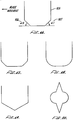
- the blade cross section can be changed so it is no longer rectangular.
- the bottom of the blade can be constructed so that the non-horizontal edges of the blade near the bottom form angles, identified with reference numerals 506 and 507, known as the angles of attack and separation, respectively, with the resin surface.
- the angle of attack is the angle in the direction of blade movement while the angle of separation is the angle at the other end.
- These angles are added to better improve resin flow underneath the blade. Without these angles, turbulence could be generated underneath the blade, which could create bubbles. These bubbles are problematic since they may travel along with the blade underneath it and be left at the surface of the part after the blade has travelled over it. As a result, they may turn up as an imperfection in the part.
- angles can range between about 5 and 8 degrees, and in addition, the angle of attack can differ from the angle of separation. For the SLA-500, an angle of attack of 6 degrees is used.
- the blade in FIG. 16 is shown as bisymmetric so that it can sweep in either direction.
- two asymmetric blades could be used alternatively to sweep in either direction with angles of attack in the direction of movement.
- Other blade configurations are possible.
- FIG. 17 shows the blade of FIG. 16 where each vertex point is rounded. This may further reduce turbulence.
- FIG. 18 shows a version where the entire bottom is rounded.
- FIG: 19 shows a version where the bottom is a sharp vertex.
- the levelling apparatus of the SLA-500 will now be described.
- This apparatus overcomes a problem which may occur with the bi-cell detector apparatus described earlier.
- the bi-cell apparatus may be sensitive to bubbles.
- a side tank is added in which bubbles are not formed, and the resin level is detected in the side vat.
- the resin level in the side tank may not be an accurate determinate of the resin level in the main vat, as is assumed. This is because during part building, resin in the main vat may be used up disproportionally compared with the side tank. Because of this disproportionality, the liquid in the side tank, when viewed as a whole, may not be as dense as that in the main vat. This may cause the resin level in the side tank to falsely read too high.
- an apparatus including a float is employed in the SLA-500 to detect the resin level in the main vat instead of the bi-cell apparatus described earlier.
- the float has the advantage that it is relatively insensitive to bubbles, and so can be used to detect the level of the resin in the main vat as opposed to a side tank. This is because a bubble which attaches to the side of the float will not change its mass, and hence the level at which it floats. Therefore, a side tank is not needed, and the float will accurately detect the resin level even if a layer of resin were floated on a heavy, immiscible fluid.
- the float can take many shapes.
- the float is presently in the shape of a small can, having a volume of about 50 cc or more.
- the float is advantageously teflon coated, so that any resin that gets on the top, or wets the sides of the float, will rapidly drip or slide off, and not substantially change the mass of the float for an appreciable period of time.
- the float apparatus presently used in the SLA-500 is illustrated in FIG. 21.
- the apparatus comprises float 602, supporting beam 603, bearing 604, and optical detection circuitry 605.
- the supporting beam is coupled to the float, which floats on resin surface 601 placed in vat 600.
- the beam is also vertically rotatable around bearing 604.
- bearing 604 is advantageously a class 9 bearing.
- the optical detection circuitry 605 is shown in detail in FIG. 22. As illustrated, the circuitry comprises member 6051 which is coupled to beam 603, light-emitting diodes ("LEDs") 6052 and 6053, which emit light beams 6056 and 6057, respectively, and optical detectors 6054 and 6055, which detect the uninterrupted presence of light beams 6056 and 6057, respectively.
- the optical detectors are electronically coupled to a plunger or other means (not shown) described earlier for raising or lowering the resin level in response to electrical signals from the optical detectors.
- the resin level is assumed to be at the correct height. Only when member 6051 is deflected sufficiently to block the passage of one of the light beams to its corresponding optical detector, which will be detected by the failure of the optical detector to pick up any light from its corresponding LED, will it be assumed that the resin it at an incorrect level. In this instance, a plunger or other means electrically coupled to the optical detectors will be either raised or lowered in order to position the resin level, and hence float, at the correct height.
- the recoating software used in the SLA-250 will now be described.
- a specification for the software in the form of a flowchart is illustrated in FIG. 23.
- a user Before utilizing the software, a user must first specify certain parameters that will be used to control the movement of the platform. These parameters are ZA, ZV, ZW, and ZD.
- the platform is under the control of a computer known as the PROCESS computer.
- ZA is the amount the PROCESS computer will allow the platform to accelerate or deaccelerate
- ZV the maximum velocity the platform will be allowed to achieve
- ZD is the depth the platform is caused to overdip into the liquid resin before sweeping.
- ZD is typically much greater than a layer thickness.
- ZW is the settling delay, which is the amount of time the PROCESS computer is directed to wait after the platform has been lowered after sweeping to place the upper surface of the resin layer on top of the part at the same level as the resin in the vat.
- the PROCESS computer will wait the amount of time specified by ZW before curing the resin on top of the part.
- the user may specify other variables for each layer or range of layers including SN, which is the number of sweeps per layer, and GV, which stands for global velocity, and indicates that all sweeps are to be made at the specified velocity.
- the user also may specify V1-V7, which are individual velocities associated with sweeps 1-7, respectively. By setting these values, the user indicates he or she wishes velocity to vary by sweep.
- step 700 when layer N is drawn.
- step 701 the platform is lowered beneath the resin surface by ZD at a speed determined by ZA and ZV.
- step 703 a post-dip delay is implemented to allow settling of the resin since the platform has just been moved.
- step 704 a reading from the bi-cell detector is taken and corrected for a bias introduced by the circuitry (identified as BCVAL-BIAS). The reading is then compared with an upper limit, identified as UPLIM, and a lower limit, identified as LOWLIM. If between these two values, the resin level is assumed to be at the correct height.
- step 705 a flag is checked to see if set.
- the flag is set in response to a key pushed by the user, which indicates that the user manually has added or taken away resin from the vat.
- step 708 a check is made to determine that SN, the number of sweeps for layer N+1, is greater than 0, and that the platform is still in a safe position so that the blade will not strike it while sweeping.
- the upper bound for the platform position is identified by the mnemonic NOSWEEP.
- step 709 an internal counter, SWEEP, is first initialized to 0, and then incremented.
- step 712 a check is made to determine whether the blade is at the front or back of the vat. Assuming the front for the moment, in step 713, the blade is swept to the back of the vat (which is a distance specified by SWEEPDIST) at a velocity which may depend on the current value of SWEEP.
- step 727 a check is made to determine whether all the sweeps specified by SN have been performed for the layer. Assuming they have not, a jump is made back to step 709, and the above cycle repeated.
- step 714 in the case where the limit switch has not been activated, the blade is slowly moved towards the rear at the velocity of .5 in/sec., and assuming the limit switch is activated within 2 seconds, a jump is made to step 722. Assuming it is not so activated, the process is aborted in step 721.
- step 717 the blade is swept towards the front at a velocity which may be a function of the current sweep number, and in step 718, a check is made to see if the limit switch has been activated. Assuming it has, a jump is made to step 722. If it has not, in step 719, the blade is slowly moved towards the front at a velocity of .5 in/sec., and if the limit switch is activated within 2 sec., a jump is made to step 722. If it is not, the process is aborted in step 721.
- step 704 which is right after the platform (and part) have been overdipped below the resin surface, if the resin level is not at the appropriate height, a check is made in step 723 to see if it is too high or too low. If BCVAL-BIAS is greater than UPLIM, the resin level is too low, and the plunger must then be lowered.
- step 724 a check is made to see if the plunger is already at the bottom of the vat, and assuming it is not, in steps 725 and 726, the plunger is lowered, and the plunger position, identified with the mnemonic PLUNGPOS, is updated.
- step 727 a delay is instituted to allow the resin to settle, and a jump is made to step 704 to check the resin level again. The above cycle then repeats.
- step 724 assuming the plunger is at the bottom of the vat, the only way to raise the level is to add resin to the vat.
- step 732 the level is checked again, and assuming it is still too low, in steps 733-734, the user is asked to press a key indicating he or she will manually add resin. Until the key is pressed, the process will loop. When the key is pressed, a flag is set (the same flag which is checked in step 705). While the user presumably adds resin to the vat, in step 739, the process will loop until the resin level is at the current level. When it is, in step 740, a message is sent to the user indicating that enough resin has been added, and a jump is made to step 704.
- step 705 after the resin has been added so that the resin level is at the correct height, the flag must be reset. This condition is detected in steps 705 and 706, and in step 707, the flag is reset.
- step 723 in the case where BCVAL-BIAS is less than LOWLIM, indicating that the resin level is too high, the plunger must be raised.
- a check is made in step 728 to see if the plunger is already at its highest possible position, indicated by 0. Assuming it is not, in steps 729-730, the plunger is raised, and the plunger position, identified as PLUNGPOS, is updated. Then, in step 731, a settling delay is instituted, and a jump is made back to step 704.
- step 741 a check is made to determine that the resin level is still too high, and in steps 742-743, the user is sent a message, asking him or her to remove resin, and is asked to press a key acknowledging the message. Until the key is pressed, the process will loop.
- step 744 a flag is set, and in step 745, while the user is removing resin, the resin level is checked until it is at the appropriate height. Until it is, the process will loop.
- step 746 the user is notified to stop removing resin, and a jump made back to step 704.
- the flag is reset.
- levelling need not be performed at each layer, but only when the level may have changed because of any of the following: 1) thermal expansion; 2) shrinkage; and 3) changing displacement caused by platform supports. If neither of these are present, levelling need not be conducted for a layer.
- step 749 when all the sweeps for layer N+1 have been performed, a settling delay equal to ZW will be instituted, and in steps 750-751, the vectors for layer N+1 are computed, and the layer drawn using these vectors in step 751. More detail on computing vectors and drawing layers is provided in U.S. Patent Application S.N. 331,644.
- BUILD is the program which orchestrates the building of a part.
- the programs will, in the usual instance, be used in conjunction with BUILD. Together, these programs will provide functionabilty substantially similar to that described above with respect to FIG. 23.
- RECOATER.PAS provides a means to perform recoating independent of BUILD. The software listings follow:
Applications Claiming Priority (5)
| Application Number | Priority Date | Filing Date | Title |
|---|---|---|---|
| US24939988A | 1988-09-26 | 1988-09-26 | |
| US249399 | 1988-09-26 | ||
| US26503988A | 1988-10-31 | 1988-10-31 | |
| US265039 | 1988-10-31 | ||
| EP89309762A EP0361847B1 (fr) | 1988-09-26 | 1989-09-26 | Application de couches stéréolithographiques |
Related Parent Applications (2)
| Application Number | Title | Priority Date | Filing Date |
|---|---|---|---|
| EP89309762.6 Division | 1989-09-26 | ||
| EP89309762A Division EP0361847B1 (fr) | 1988-09-26 | 1989-09-26 | Application de couches stéréolithographiques |
Publications (3)
| Publication Number | Publication Date |
|---|---|
| EP0681904A2 true EP0681904A2 (fr) | 1995-11-15 |
| EP0681904A3 EP0681904A3 (fr) | 1996-02-07 |
| EP0681904B1 EP0681904B1 (fr) | 2002-01-09 |
Family
ID=26940037
Family Applications (3)
| Application Number | Title | Priority Date | Filing Date |
|---|---|---|---|
| EP89309762A Expired - Lifetime EP0361847B1 (fr) | 1988-09-26 | 1989-09-26 | Application de couches stéréolithographiques |
| EP95107870A Expired - Lifetime EP0681905B1 (fr) | 1988-09-26 | 1989-09-26 | Dépôt de égalisation de couches stéréolithographiques |
| EP95107869A Expired - Lifetime EP0681904B1 (fr) | 1988-09-26 | 1989-09-26 | Appareil de stéréolithographie avec moyens pour mesurer et contrôler le niveau de fluide |
Family Applications Before (2)
| Application Number | Title | Priority Date | Filing Date |
|---|---|---|---|
| EP89309762A Expired - Lifetime EP0361847B1 (fr) | 1988-09-26 | 1989-09-26 | Application de couches stéréolithographiques |
| EP95107870A Expired - Lifetime EP0681905B1 (fr) | 1988-09-26 | 1989-09-26 | Dépôt de égalisation de couches stéréolithographiques |
Country Status (11)
| Country | Link |
|---|---|
| EP (3) | EP0361847B1 (fr) |
| JP (3) | JP3030855B2 (fr) |
| KR (1) | KR100189270B1 (fr) |
| AT (3) | ATE200644T1 (fr) |
| CA (1) | CA1337955C (fr) |
| DE (3) | DE68929292T2 (fr) |
| ES (1) | ES2082782T3 (fr) |
| HK (3) | HK1002908A1 (fr) |
| IL (1) | IL91784A (fr) |
| SG (1) | SG49722A1 (fr) |
| WO (1) | WO1990003255A1 (fr) |
Cited By (4)
| Publication number | Priority date | Publication date | Assignee | Title |
|---|---|---|---|---|
| DE10227673B4 (de) * | 2001-06-20 | 2007-04-05 | Hamacher, Renate | Füllstandsanzeige |
| RU2345888C2 (ru) * | 2002-04-17 | 2009-02-10 | Стратасис, Инк. | Способ выравнивания при моделировании методом наслоения |
| WO2018140028A1 (fr) * | 2017-01-27 | 2018-08-02 | Hewlett Packard Development Company, L.P. | Positionnement automatique de matériau de lame de palonnier pour fabrication additive |
| CN109278288A (zh) * | 2017-07-21 | 2019-01-29 | Cl产权管理有限公司 | 用于添加式地制造三维物体的设备 |
Families Citing this family (71)
| Publication number | Priority date | Publication date | Assignee | Title |
|---|---|---|---|---|
| US5094935A (en) * | 1990-06-26 | 1992-03-10 | E. I. Dupont De Nemours And Company | Method and apparatus for fabricating three dimensional objects from photoformed precursor sheets |
| DE4112695C3 (de) * | 1990-12-21 | 1998-07-23 | Eos Electro Optical Syst | Verfahren und Vorrichtung zum Herstellen eines dreidimensionalen Objekts |
| US5460758A (en) * | 1990-12-21 | 1995-10-24 | Eos Gmbh Electro Optical Systems | Method and apparatus for production of a three-dimensional object |
| DE59101958D1 (de) * | 1990-12-21 | 1994-07-21 | Eos Electro Optical Syst | Verfahren und vorrichtung zum herstellen eines dreidimensionalen objekts. |
| US5474719A (en) * | 1991-02-14 | 1995-12-12 | E. I. Du Pont De Nemours And Company | Method for forming solid objects utilizing viscosity reducible compositions |
| DE4134265C2 (de) * | 1991-10-16 | 1993-11-25 | Eos Electro Optical Syst | Vorrichtung und Verfahren zur Herstellung eines dreidimensionalen Objekts mittels Stereographie |
| JP2805674B2 (ja) * | 1993-03-22 | 1998-09-30 | ソニー株式会社 | 光学的造形方法および光学的造形装置 |
| FR2713541B1 (fr) * | 1993-12-09 | 1997-04-30 | Laser Int Sa | Procédé et installation pour la fabrication de pièces par phototransformation de matière. |
| DE19514740C1 (de) * | 1995-04-21 | 1996-04-11 | Eos Electro Optical Syst | Vorrichtung und Verfahren zum Herstellen eines dreidimensionalen Objektes |
| DE19515165C2 (de) * | 1995-04-25 | 1997-03-06 | Eos Electro Optical Syst | Vorrichtung zum Herstellen eines Objektes mittels Stereolithographie |
| US5945058A (en) * | 1997-05-13 | 1999-08-31 | 3D Systems, Inc. | Method and apparatus for identifying surface features associated with selected lamina of a three-dimensional object being stereolithographically formed |
| US5910319A (en) * | 1997-05-29 | 1999-06-08 | Eli Lilly And Company | Fluoxetine enteric pellets and methods for their preparation and use |
| FR2790418B1 (fr) | 1999-03-01 | 2001-05-11 | Optoform Sarl Procedes De Prot | Procede de prototypage rapide permettant l'utilisation de materiaux pateux, et dispositif pour sa mise en oeuvre |
| DE10085198D2 (de) | 2000-09-25 | 2003-08-21 | Generis Gmbh | Verfahren zum Herstellen eines Bauteils in Ablagerungstechnik |
| DE10047614C2 (de) | 2000-09-26 | 2003-03-27 | Generis Gmbh | Vorrichtung zum schichtweisen Aufbau von Modellen |
| DE10047615A1 (de) | 2000-09-26 | 2002-04-25 | Generis Gmbh | Wechselbehälter |
| DE10117875C1 (de) | 2001-04-10 | 2003-01-30 | Generis Gmbh | Verfahren, Vorrichtung zum Auftragen von Fluiden sowie Verwendung einer solchen Vorrichtung |
| DE10222167A1 (de) | 2002-05-20 | 2003-12-04 | Generis Gmbh | Vorrichtung zum Zuführen von Fluiden |
| US7807077B2 (en) | 2003-06-16 | 2010-10-05 | Voxeljet Technology Gmbh | Methods and systems for the manufacture of layered three-dimensional forms |
| DE10327272A1 (de) | 2003-06-17 | 2005-03-03 | Generis Gmbh | Verfahren zum schichtweisen Aufbau von Modellen |
| DE102004008168B4 (de) | 2004-02-19 | 2015-12-10 | Voxeljet Ag | Verfahren und Vorrichtung zum Auftragen von Fluiden und Verwendung der Vorrichtung |
| DE102004025374A1 (de) | 2004-05-24 | 2006-02-09 | Technische Universität Berlin | Verfahren und Vorrichtung zum Herstellen eines dreidimensionalen Artikels |
| JP4034758B2 (ja) * | 2004-06-04 | 2008-01-16 | 独立行政法人科学技術振興機構 | 光造形ファブリケーション法を利用した金属構造体の製造方法 |
| US7585450B2 (en) * | 2005-09-30 | 2009-09-08 | 3D Systems, Inc. | Rapid prototyping and manufacturing system and method |
| US7690909B2 (en) * | 2005-09-30 | 2010-04-06 | 3D Systems, Inc. | Rapid prototyping and manufacturing system and method |
| DE102006030350A1 (de) | 2006-06-30 | 2008-01-03 | Voxeljet Technology Gmbh | Verfahren zum Aufbauen eines Schichtenkörpers |
| DE102006038858A1 (de) | 2006-08-20 | 2008-02-21 | Voxeljet Technology Gmbh | Selbstaushärtendes Material und Verfahren zum schichtweisen Aufbau von Modellen |
| DE102007033434A1 (de) | 2007-07-18 | 2009-01-22 | Voxeljet Technology Gmbh | Verfahren zum Herstellen dreidimensionaler Bauteile |
| US10226919B2 (en) | 2007-07-18 | 2019-03-12 | Voxeljet Ag | Articles and structures prepared by three-dimensional printing method |
| DE102007049058A1 (de) | 2007-10-11 | 2009-04-16 | Voxeljet Technology Gmbh | Materialsystem und Verfahren zum Verändern von Eigenschaften eines Kunststoffbauteils |
| DE102007050679A1 (de) | 2007-10-21 | 2009-04-23 | Voxeljet Technology Gmbh | Verfahren und Vorrichtung zum Fördern von Partikelmaterial beim schichtweisen Aufbau von Modellen |
| DE102007050953A1 (de) | 2007-10-23 | 2009-04-30 | Voxeljet Technology Gmbh | Vorrichtung zum schichtweisen Aufbau von Modellen |
| DE102008058378A1 (de) | 2008-11-20 | 2010-05-27 | Voxeljet Technology Gmbh | Verfahren zum schichtweisen Aufbau von Kunststoffmodellen |
| DE102010006939A1 (de) | 2010-02-04 | 2011-08-04 | Voxeljet Technology GmbH, 86167 | Vorrichtung zum Herstellen dreidimensionaler Modelle |
| DE102010013733A1 (de) | 2010-03-31 | 2011-10-06 | Voxeljet Technology Gmbh | Vorrichtung zum Herstellen dreidimensionaler Modelle |
| DE102010013732A1 (de) | 2010-03-31 | 2011-10-06 | Voxeljet Technology Gmbh | Vorrichtung zum Herstellen dreidimensionaler Modelle |
| DE102010014969A1 (de) | 2010-04-14 | 2011-10-20 | Voxeljet Technology Gmbh | Vorrichtung zum Herstellen dreidimensionaler Modelle |
| DE102010015451A1 (de) | 2010-04-17 | 2011-10-20 | Voxeljet Technology Gmbh | Verfahren und Vorrichtung zum Herstellen dreidimensionaler Objekte |
| DE102010056346A1 (de) | 2010-12-29 | 2012-07-05 | Technische Universität München | Verfahren zum schichtweisen Aufbau von Modellen |
| DE102011007957A1 (de) | 2011-01-05 | 2012-07-05 | Voxeljet Technology Gmbh | Vorrichtung und Verfahren zum Aufbauen eines Schichtenkörpers mit wenigstens einem das Baufeld begrenzenden und hinsichtlich seiner Lage einstellbaren Körper |
| DE102011111498A1 (de) | 2011-08-31 | 2013-02-28 | Voxeljet Technology Gmbh | Vorrichtung zum schichtweisen Aufbau von Modellen |
| DE102012004213A1 (de) | 2012-03-06 | 2013-09-12 | Voxeljet Technology Gmbh | Verfahren und Vorrichtung zum Herstellen dreidimensionaler Modelle |
| DE102012010272A1 (de) | 2012-05-25 | 2013-11-28 | Voxeljet Technology Gmbh | Verfahren zum Herstellen dreidimensionaler Modelle mit speziellen Bauplattformen und Antriebssystemen |
| DE102012012363A1 (de) | 2012-06-22 | 2013-12-24 | Voxeljet Technology Gmbh | Vorrichtung zum Aufbauen eines Schichtenkörpers mit entlang des Austragbehälters bewegbarem Vorrats- oder Befüllbehälter |
| DE102012020000A1 (de) | 2012-10-12 | 2014-04-17 | Voxeljet Ag | 3D-Mehrstufenverfahren |
| DE102013004940A1 (de) | 2012-10-15 | 2014-04-17 | Voxeljet Ag | Verfahren und Vorrichtung zum Herstellen von dreidimensionalen Modellen mit temperiertem Druckkopf |
| DE102012022859A1 (de) | 2012-11-25 | 2014-05-28 | Voxeljet Ag | Aufbau eines 3D-Druckgerätes zur Herstellung von Bauteilen |
| DE102013003303A1 (de) | 2013-02-28 | 2014-08-28 | FluidSolids AG | Verfahren zum Herstellen eines Formteils mit einer wasserlöslichen Gussform sowie Materialsystem zu deren Herstellung |
| DE102013018182A1 (de) | 2013-10-30 | 2015-04-30 | Voxeljet Ag | Verfahren und Vorrichtung zum Herstellen von dreidimensionalen Modellen mit Bindersystem |
| DE102013018031A1 (de) | 2013-12-02 | 2015-06-03 | Voxeljet Ag | Wechselbehälter mit verfahrbarer Seitenwand |
| DE102013020491A1 (de) | 2013-12-11 | 2015-06-11 | Voxeljet Ag | 3D-Infiltrationsverfahren |
| EP2886307A1 (fr) | 2013-12-20 | 2015-06-24 | Voxeljet AG | Dispositif, papier spécial et procédé de fabrication de pièces moulées |
| DE102014004692A1 (de) | 2014-03-31 | 2015-10-15 | Voxeljet Ag | Verfahren und Vorrichtung für den 3D-Druck mit klimatisierter Verfahrensführung |
| DE102014007584A1 (de) | 2014-05-26 | 2015-11-26 | Voxeljet Ag | 3D-Umkehrdruckverfahren und Vorrichtung |
| US10946556B2 (en) | 2014-08-02 | 2021-03-16 | Voxeljet Ag | Method and casting mold, in particular for use in cold casting methods |
| NL2013861B1 (en) * | 2014-11-24 | 2016-10-11 | Additive Ind Bv | Apparatus for producing an object by means of additive manufacturing. |
| DE102015006533A1 (de) | 2014-12-22 | 2016-06-23 | Voxeljet Ag | Verfahren und Vorrichtung zum Herstellen von 3D-Formteilen mit Schichtaufbautechnik |
| DE102015102221A1 (de) * | 2015-02-17 | 2016-08-18 | Krones Ag | Verfahren zum Herstellen einer Vorrichtung zum Tragen von zu reinigenden Behältern, sowie Vorrichtung zum Tragen von zu reinigenden Behältern |
| DE102015003372A1 (de) | 2015-03-17 | 2016-09-22 | Voxeljet Ag | Verfahren und Vorrichtung zum Herstellen von 3D-Formteilen mit Doppelrecoater |
| DE102015006363A1 (de) | 2015-05-20 | 2016-12-15 | Voxeljet Ag | Phenolharzverfahren |
| DE102015011503A1 (de) | 2015-09-09 | 2017-03-09 | Voxeljet Ag | Verfahren zum Auftragen von Fluiden |
| DE102015011790A1 (de) | 2015-09-16 | 2017-03-16 | Voxeljet Ag | Vorrichtung und Verfahren zum Herstellen dreidimensionaler Formteile |
| DE102015015353A1 (de) | 2015-12-01 | 2017-06-01 | Voxeljet Ag | Verfahren und Vorrichtung zur Herstellung von dreidimensionalen Bauteilen mittels Überschussmengensensor |
| DE102016013610A1 (de) | 2016-11-15 | 2018-05-17 | Voxeljet Ag | Intregierte Druckkopfwartungsstation für das pulverbettbasierte 3D-Drucken |
| GB201704676D0 (en) | 2017-03-24 | 2017-05-10 | Rolls Royce Plc | Recoater for additive layer manufature |
| DE102017006860A1 (de) | 2017-07-21 | 2019-01-24 | Voxeljet Ag | Verfahren und Vorrichtung zum Herstellen von 3D-Formteilen mit Spektrumswandler |
| US11104075B2 (en) | 2018-11-01 | 2021-08-31 | Stratasys, Inc. | System for window separation in an additive manufacturing process |
| CA3118364A1 (fr) | 2018-11-01 | 2020-05-07 | Stratasys, Inc. | Procede de separation de construction vis-a-vis d'une interface de durcissement dans un processus de fabrication additive |
| DE102019000796A1 (de) | 2019-02-05 | 2020-08-06 | Voxeljet Ag | Wechselbare Prozesseinheit |
| DE102019007595A1 (de) | 2019-11-01 | 2021-05-06 | Voxeljet Ag | 3d-druckverfahren und damit hergestelltes formteil unter verwendung von ligninsulfat |
| CN116499958B (zh) * | 2023-06-29 | 2023-09-01 | 德阳市产品质量监督检验所 | 一种材料腐蚀程度实时监测装置及监测方法 |
Citations (9)
| Publication number | Priority date | Publication date | Assignee | Title |
|---|---|---|---|---|
| GB1083489A (en) * | 1965-09-07 | 1967-09-13 | Gen Motors Corp | Indicator apparatus |
| EP0014301A1 (fr) * | 1978-12-20 | 1980-08-20 | CEDA S.p.A. | Dispositif de mesure de niveaux |
| US4247784A (en) * | 1978-12-18 | 1981-01-27 | Eastman Kodak Company | Measurement of material level in vessels |
| US4247508A (en) * | 1979-12-03 | 1981-01-27 | Hico Western Products Co. | Molding process |
| JPS56100316A (en) * | 1980-01-16 | 1981-08-12 | Hirakawa Denki Kk | Liquid level indicator for molten glass |
| FR2482290A1 (fr) * | 1980-05-09 | 1981-11-13 | Poncet Pierre | Perfectionnements a la detection photoelectrique du niveau du bain dans les lingotieres de coulee continue |
| EP0171069A2 (fr) * | 1984-08-08 | 1986-02-12 | 3D SYSTEMS, INC. (a California corporation) | Procédé et appareil stéréolithographique pour la fabrication d'objets en trois dimensions |
| JPS61114818A (ja) * | 1984-11-09 | 1986-06-02 | Fujitsu Ltd | 立体形状形成装置 |
| JPS6237109A (ja) * | 1985-08-10 | 1987-02-18 | Fujitsu Ltd | 立体形状形成装置 |
Family Cites Families (5)
| Publication number | Priority date | Publication date | Assignee | Title |
|---|---|---|---|---|
| US2621808A (en) * | 1945-08-24 | 1952-12-16 | Frazier Simplex | Apparatus responsive to variations in liquid level |
| US3953845A (en) * | 1975-02-04 | 1976-04-27 | Lawrence Peska Associates, Inc. | Oil level indicator |
| US4508970A (en) * | 1982-07-15 | 1985-04-02 | Motorola, Inc. | Melt level sensing system and method |
| JPS60147615A (ja) * | 1984-01-13 | 1985-08-03 | Hitachi Ltd | 液面測定方法 |
| DE3750709T2 (de) * | 1986-06-03 | 1995-03-16 | Cubital Ltd | Gerät zur Entwicklung dreidimensionaler Modelle. |
-
1989
- 1989-09-25 CA CA612990A patent/CA1337955C/fr not_active Expired - Fee Related
- 1989-09-26 AT AT95107870T patent/ATE200644T1/de not_active IP Right Cessation
- 1989-09-26 EP EP89309762A patent/EP0361847B1/fr not_active Expired - Lifetime
- 1989-09-26 DE DE68929292T patent/DE68929292T2/de not_active Expired - Lifetime
- 1989-09-26 SG SG1996004356A patent/SG49722A1/en unknown
- 1989-09-26 DE DE68929366T patent/DE68929366T2/de not_active Expired - Lifetime
- 1989-09-26 IL IL91784A patent/IL91784A/xx not_active IP Right Cessation
- 1989-09-26 JP JP1511123A patent/JP3030855B2/ja not_active Expired - Fee Related
- 1989-09-26 AT AT95107869T patent/ATE211679T1/de active
- 1989-09-26 EP EP95107870A patent/EP0681905B1/fr not_active Expired - Lifetime
- 1989-09-26 AT AT89309762T patent/ATE130793T1/de active
- 1989-09-26 EP EP95107869A patent/EP0681904B1/fr not_active Expired - Lifetime
- 1989-09-26 ES ES89309762T patent/ES2082782T3/es not_active Expired - Lifetime
- 1989-09-26 WO PCT/US1989/004096 patent/WO1990003255A1/fr active Application Filing
- 1989-09-26 KR KR1019900701102A patent/KR100189270B1/ko not_active IP Right Cessation
- 1989-09-26 DE DE68924952T patent/DE68924952T2/de not_active Expired - Lifetime
-
1998
- 1998-01-22 HK HK98100602A patent/HK1002908A1/xx not_active IP Right Cessation
- 1998-03-12 HK HK98102087A patent/HK1004477A1/xx not_active IP Right Cessation
- 1998-08-31 HK HK98110328A patent/HK1009595A1/xx not_active IP Right Cessation
-
2000
- 2000-01-05 JP JP2000000410A patent/JP3373830B2/ja not_active Expired - Lifetime
-
2001
- 2001-03-12 JP JP2001069484A patent/JP3359026B2/ja not_active Expired - Lifetime
Patent Citations (10)
| Publication number | Priority date | Publication date | Assignee | Title |
|---|---|---|---|---|
| GB1083489A (en) * | 1965-09-07 | 1967-09-13 | Gen Motors Corp | Indicator apparatus |
| US4247784A (en) * | 1978-12-18 | 1981-01-27 | Eastman Kodak Company | Measurement of material level in vessels |
| EP0014301A1 (fr) * | 1978-12-20 | 1980-08-20 | CEDA S.p.A. | Dispositif de mesure de niveaux |
| US4247508A (en) * | 1979-12-03 | 1981-01-27 | Hico Western Products Co. | Molding process |
| US4247508B1 (en) * | 1979-12-03 | 1996-10-01 | Dtm Corp | Molding process |
| JPS56100316A (en) * | 1980-01-16 | 1981-08-12 | Hirakawa Denki Kk | Liquid level indicator for molten glass |
| FR2482290A1 (fr) * | 1980-05-09 | 1981-11-13 | Poncet Pierre | Perfectionnements a la detection photoelectrique du niveau du bain dans les lingotieres de coulee continue |
| EP0171069A2 (fr) * | 1984-08-08 | 1986-02-12 | 3D SYSTEMS, INC. (a California corporation) | Procédé et appareil stéréolithographique pour la fabrication d'objets en trois dimensions |
| JPS61114818A (ja) * | 1984-11-09 | 1986-06-02 | Fujitsu Ltd | 立体形状形成装置 |
| JPS6237109A (ja) * | 1985-08-10 | 1987-02-18 | Fujitsu Ltd | 立体形状形成装置 |
Non-Patent Citations (4)
| Title |
|---|
| ADVANCES IN INSTRUMENTATION, vol. 32, no. 4, 1977 RESEARCH TRIANGLE PARK US, pages 151-156, D. TAYLOR 'An economical method of glass level control utilising a laser beam generator and a solid state detector' * |
| PATENT ABSTRACTS OF JAPAN vol. 10 no. 301 (M-525) [2357] ,14 October 1986 & JP-A-61 114818 (FUJITSU LTD) 2 June 1986, * |
| PATENT ABSTRACTS OF JAPAN vol. 11 no. 221 (M-608) [2668] ,17 July 1987 & JP-A-62 037109 (FUJITSU LTD) 18 February 1987, * |
| PATENT ABSTRACTS OF JAPAN vol. 5 no. 173 (P-87) [845] ,5 November 1981 & JP-A-56 100316 (HIRAKAWA DENKI K.K.) 12 August 1981, * |
Cited By (5)
| Publication number | Priority date | Publication date | Assignee | Title |
|---|---|---|---|---|
| DE10227673B4 (de) * | 2001-06-20 | 2007-04-05 | Hamacher, Renate | Füllstandsanzeige |
| RU2345888C2 (ru) * | 2002-04-17 | 2009-02-10 | Стратасис, Инк. | Способ выравнивания при моделировании методом наслоения |
| WO2018140028A1 (fr) * | 2017-01-27 | 2018-08-02 | Hewlett Packard Development Company, L.P. | Positionnement automatique de matériau de lame de palonnier pour fabrication additive |
| CN109278288A (zh) * | 2017-07-21 | 2019-01-29 | Cl产权管理有限公司 | 用于添加式地制造三维物体的设备 |
| CN109278288B (zh) * | 2017-07-21 | 2021-10-08 | Cl产权管理有限公司 | 用于添加式地制造三维物体的设备 |
Also Published As
| Publication number | Publication date |
|---|---|
| EP0681905B1 (fr) | 2001-04-18 |
| DE68924952D1 (de) | 1996-01-11 |
| EP0681904A3 (fr) | 1996-02-07 |
| HK1009595A1 (en) | 1999-06-04 |
| HK1002908A1 (en) | 1998-09-25 |
| ATE130793T1 (de) | 1995-12-15 |
| IL91784A (en) | 1993-07-08 |
| EP0361847B1 (fr) | 1995-11-29 |
| CA1337955C (fr) | 1996-01-23 |
| DE68929366D1 (de) | 2002-02-14 |
| JP3030855B2 (ja) | 2000-04-10 |
| KR100189270B1 (ko) | 1999-06-01 |
| DE68929292T2 (de) | 2001-08-23 |
| IL91784A0 (en) | 1990-06-10 |
| EP0681905A1 (fr) | 1995-11-15 |
| DE68929366T2 (de) | 2002-09-26 |
| DE68929292D1 (de) | 2001-05-23 |
| JP3373830B2 (ja) | 2003-02-04 |
| SG49722A1 (en) | 1998-06-15 |
| EP0361847A2 (fr) | 1990-04-04 |
| JPH04503634A (ja) | 1992-07-02 |
| ATE211679T1 (de) | 2002-01-15 |
| WO1990003255A1 (fr) | 1990-04-05 |
| JP3359026B2 (ja) | 2002-12-24 |
| JP2000141496A (ja) | 2000-05-23 |
| KR900701494A (ko) | 1990-12-03 |
| ES2082782T3 (es) | 1996-04-01 |
| HK1004477A1 (en) | 1998-11-27 |
| EP0361847A3 (fr) | 1991-10-09 |
| JP2001287272A (ja) | 2001-10-16 |
| EP0681904B1 (fr) | 2002-01-09 |
| ATE200644T1 (de) | 2001-05-15 |
| DE68924952T2 (de) | 1996-06-13 |
Similar Documents
| Publication | Publication Date | Title |
|---|---|---|
| EP0681905B1 (fr) | Dépôt de égalisation de couches stéréolithographiques | |
| US5891382A (en) | Recoating of stereolithographic layers | |
| US5174931A (en) | Method of and apparatus for making a three-dimensional product by stereolithography | |
| JP3060179B2 (ja) | 物体製造装置 | |
| CN201070835Y (zh) | 一种用于光固化快速成型设备的树脂液面控制及涂覆装置 | |
| CN1900871A (zh) | 一种用于光固化快速成型的树脂液位控制系统 | |
| JP2715636B2 (ja) | 立体形状形成装置における樹脂貯留槽の液面制御機構 | |
| JP2001287273A (ja) | 立体造形方法及び装置 | |
| KR0178875B1 (ko) | 평탄화 기구를 사용하여 매질의 층을 형성하는 스테레오리토그라피에 의하여 3차원 물체를 형성하는 방법 및 장치 | |
| JP3419724B2 (ja) | 液面レベル測定装置および立体造形装置 | |
| JPH08338753A (ja) | 光硬化性液の液面高さ測定装置 | |
| JP3294833B2 (ja) | 立体造形方法及び装置 | |
| CN112936848A (zh) | 三维打印方法、设备和计算机可读介质 | |
| CN214324202U (zh) | 3d打印设备及其液位调节系统 | |
| CN113752549A (zh) | 光固化型三维打印装置和三维打印方法 | |
| KR20190023014A (ko) | 광경화성 3d 프린터 및 제품 성형방법 | |
| JP2901320B2 (ja) | 三次元形状の形成方法 | |
| CN112497753A (zh) | 液位调节系统、3d打印设备及3d打印方法 | |
| EP4197743A1 (fr) | Imprimante 3d ascendante, plate-forme pour cette imprimante et procédé d'impression 3d | |
| JPH07304104A (ja) | 光造形品の形成方法および装置 | |
| CN115625891B (zh) | 一种基于线阵扫描MicroLED的3D打印设备 | |
| KR102562205B1 (ko) | 3d 프린터의 출력 방법 | |
| CN210759259U (zh) | 一种红外3d打印机调平装置 | |
| KR102589111B1 (ko) | 3d 프린터의 출력 오류 검출방법 | |
| CN212097542U (zh) | 一种多光路光固化3d打印设备 |
Legal Events
| Date | Code | Title | Description |
|---|---|---|---|
| PUAI | Public reference made under article 153(3) epc to a published international application that has entered the european phase |
Free format text: ORIGINAL CODE: 0009012 |
|
| 17P | Request for examination filed |
Effective date: 19950523 |
|
| AC | Divisional application: reference to earlier application |
Ref document number: 361847 Country of ref document: EP |
|
| AK | Designated contracting states |
Kind code of ref document: A2 Designated state(s): AT BE CH DE ES FR GB GR IT LI LU NL SE |
|
| RIN1 | Information on inventor provided before grant (corrected) |
Inventor name: LIRAN, ABRAHAM Inventor name: LEWIS, MARK A. Inventor name: LEWIS, CHARLES W. Inventor name: JACOBS, PAUL F. Inventor name: SERKUCZEWSKI, ANDRZEJ R. Inventor name: MODREK, BORZO Inventor name: HULL, CHARLES W. Inventor name: ALMQUIST, THOMAS A. |
|
| PUAL | Search report despatched |
Free format text: ORIGINAL CODE: 0009013 |
|
| AK | Designated contracting states |
Kind code of ref document: A3 Designated state(s): AT BE CH DE ES FR GB GR IT LI LU NL SE |
|
| 17Q | First examination report despatched |
Effective date: 19980928 |
|
| GRAG | Despatch of communication of intention to grant |
Free format text: ORIGINAL CODE: EPIDOS AGRA |
|
| GRAG | Despatch of communication of intention to grant |
Free format text: ORIGINAL CODE: EPIDOS AGRA |
|
| GRAG | Despatch of communication of intention to grant |
Free format text: ORIGINAL CODE: EPIDOS AGRA |
|
| GRAH | Despatch of communication of intention to grant a patent |
Free format text: ORIGINAL CODE: EPIDOS IGRA |
|
| GRAH | Despatch of communication of intention to grant a patent |
Free format text: ORIGINAL CODE: EPIDOS IGRA |
|
| GRAA | (expected) grant |
Free format text: ORIGINAL CODE: 0009210 |
|
| REG | Reference to a national code |
Ref country code: GB Ref legal event code: IF02 |
|
| AC | Divisional application: reference to earlier application |
Ref document number: 361847 Country of ref document: EP |
|
| AK | Designated contracting states |
Kind code of ref document: B1 Designated state(s): AT BE CH DE ES FR GB GR IT LI LU NL SE |
|
| PG25 | Lapsed in a contracting state [announced via postgrant information from national office to epo] |
Ref country code: NL Free format text: LAPSE BECAUSE OF FAILURE TO SUBMIT A TRANSLATION OF THE DESCRIPTION OR TO PAY THE FEE WITHIN THE PRESCRIBED TIME-LIMIT Effective date: 20020109 Ref country code: LI Free format text: LAPSE BECAUSE OF FAILURE TO SUBMIT A TRANSLATION OF THE DESCRIPTION OR TO PAY THE FEE WITHIN THE PRESCRIBED TIME-LIMIT Effective date: 20020109 Ref country code: GR Free format text: LAPSE BECAUSE OF FAILURE TO SUBMIT A TRANSLATION OF THE DESCRIPTION OR TO PAY THE FEE WITHIN THE PRESCRIBED TIME-LIMIT Effective date: 20020109 Ref country code: CH Free format text: LAPSE BECAUSE OF FAILURE TO SUBMIT A TRANSLATION OF THE DESCRIPTION OR TO PAY THE FEE WITHIN THE PRESCRIBED TIME-LIMIT Effective date: 20020109 Ref country code: AT Free format text: LAPSE BECAUSE OF FAILURE TO SUBMIT A TRANSLATION OF THE DESCRIPTION OR TO PAY THE FEE WITHIN THE PRESCRIBED TIME-LIMIT Effective date: 20020109 |
|
| REF | Corresponds to: |
Ref document number: 211679 Country of ref document: AT Date of ref document: 20020115 Kind code of ref document: T |
|
| REG | Reference to a national code |
Ref country code: CH Ref legal event code: EP |
|
| REF | Corresponds to: |
Ref document number: 68929366 Country of ref document: DE Date of ref document: 20020214 |
|
| PG25 | Lapsed in a contracting state [announced via postgrant information from national office to epo] |
Ref country code: SE Free format text: LAPSE BECAUSE OF FAILURE TO SUBMIT A TRANSLATION OF THE DESCRIPTION OR TO PAY THE FEE WITHIN THE PRESCRIBED TIME-LIMIT Effective date: 20020409 |
|
| NLV1 | Nl: lapsed or annulled due to failure to fulfill the requirements of art. 29p and 29m of the patents act | ||
| ET | Fr: translation filed | ||
| REG | Reference to a national code |
Ref country code: CH Ref legal event code: PL |
|
| PG25 | Lapsed in a contracting state [announced via postgrant information from national office to epo] |
Ref country code: ES Free format text: LAPSE BECAUSE OF FAILURE TO SUBMIT A TRANSLATION OF THE DESCRIPTION OR TO PAY THE FEE WITHIN THE PRESCRIBED TIME-LIMIT Effective date: 20020730 |
|
| PGFP | Annual fee paid to national office [announced via postgrant information from national office to epo] |
Ref country code: BE Payment date: 20020920 Year of fee payment: 14 |
|
| PG25 | Lapsed in a contracting state [announced via postgrant information from national office to epo] |
Ref country code: LU Free format text: LAPSE BECAUSE OF NON-PAYMENT OF DUE FEES Effective date: 20020926 |
|
| PLBE | No opposition filed within time limit |
Free format text: ORIGINAL CODE: 0009261 |
|
| STAA | Information on the status of an ep patent application or granted ep patent |
Free format text: STATUS: NO OPPOSITION FILED WITHIN TIME LIMIT |
|
| 26N | No opposition filed | ||
| NLV1 | Nl: lapsed or annulled due to failure to fulfill the requirements of art. 29p and 29m of the patents act | ||
| PG25 | Lapsed in a contracting state [announced via postgrant information from national office to epo] |
Ref country code: BE Free format text: LAPSE BECAUSE OF NON-PAYMENT OF DUE FEES Effective date: 20030930 |
|
| BERE | Be: lapsed |
Owner name: *3D SYSTEMS INC. Effective date: 20030930 |
|
| PGFP | Annual fee paid to national office [announced via postgrant information from national office to epo] |
Ref country code: IT Payment date: 20080926 Year of fee payment: 20 Ref country code: FR Payment date: 20080915 Year of fee payment: 20 |
|
| PGFP | Annual fee paid to national office [announced via postgrant information from national office to epo] |
Ref country code: DE Payment date: 20081002 Year of fee payment: 20 |
|
| PGFP | Annual fee paid to national office [announced via postgrant information from national office to epo] |
Ref country code: GB Payment date: 20081001 Year of fee payment: 20 |
|
| REG | Reference to a national code |
Ref country code: FR Ref legal event code: CA |
|
| REG | Reference to a national code |
Ref country code: GB Ref legal event code: PE20 Expiry date: 20090925 |
|
| PG25 | Lapsed in a contracting state [announced via postgrant information from national office to epo] |
Ref country code: GB Free format text: LAPSE BECAUSE OF EXPIRATION OF PROTECTION Effective date: 20090925 |