EP0681818A2 - Method to control an artifical limb by miopotentials - Google Patents
Method to control an artifical limb by miopotentials Download PDFInfo
- Publication number
- EP0681818A2 EP0681818A2 EP95105327A EP95105327A EP0681818A2 EP 0681818 A2 EP0681818 A2 EP 0681818A2 EP 95105327 A EP95105327 A EP 95105327A EP 95105327 A EP95105327 A EP 95105327A EP 0681818 A2 EP0681818 A2 EP 0681818A2
- Authority
- EP
- European Patent Office
- Prior art keywords
- value
- control
- proportional
- measured
- current
- Prior art date
- Legal status (The legal status is an assumption and is not a legal conclusion. Google has not performed a legal analysis and makes no representation as to the accuracy of the status listed.)
- Granted
Links
- 238000000034 method Methods 0.000 title claims abstract description 16
- 230000003183 myoelectrical effect Effects 0.000 claims description 6
- 230000005540 biological transmission Effects 0.000 claims description 3
- 238000012935 Averaging Methods 0.000 description 4
- 230000004913 activation Effects 0.000 description 3
- 238000006243 chemical reaction Methods 0.000 description 3
- 230000006870 function Effects 0.000 description 3
- 230000000694 effects Effects 0.000 description 2
- 210000003205 muscle Anatomy 0.000 description 2
- 230000003213 activating effect Effects 0.000 description 1
- 238000013461 design Methods 0.000 description 1
- 238000001514 detection method Methods 0.000 description 1
- 238000010586 diagram Methods 0.000 description 1
- 238000011156 evaluation Methods 0.000 description 1
- 238000001914 filtration Methods 0.000 description 1
- 238000005259 measurement Methods 0.000 description 1
- 230000004118 muscle contraction Effects 0.000 description 1
- 230000000737 periodic effect Effects 0.000 description 1
- 238000005086 pumping Methods 0.000 description 1
- 230000001105 regulatory effect Effects 0.000 description 1
- 230000001960 triggered effect Effects 0.000 description 1
- 238000004804 winding Methods 0.000 description 1
Images


Classifications
-
- A—HUMAN NECESSITIES
- A61—MEDICAL OR VETERINARY SCIENCE; HYGIENE
- A61F—FILTERS IMPLANTABLE INTO BLOOD VESSELS; PROSTHESES; DEVICES PROVIDING PATENCY TO, OR PREVENTING COLLAPSING OF, TUBULAR STRUCTURES OF THE BODY, e.g. STENTS; ORTHOPAEDIC, NURSING OR CONTRACEPTIVE DEVICES; FOMENTATION; TREATMENT OR PROTECTION OF EYES OR EARS; BANDAGES, DRESSINGS OR ABSORBENT PADS; FIRST-AID KITS
- A61F2/00—Filters implantable into blood vessels; Prostheses, i.e. artificial substitutes or replacements for parts of the body; Appliances for connecting them with the body; Devices providing patency to, or preventing collapsing of, tubular structures of the body, e.g. stents
- A61F2/50—Prostheses not implantable in the body
- A61F2/68—Operating or control means
- A61F2/70—Operating or control means electrical
- A61F2/72—Bioelectric control, e.g. myoelectric
Definitions
- the invention relates to a method for the myoelectric proportional control of an electric motor-operated artificial limb, in particular a hand prosthesis, the voltage of the respective electrode signal being measured and fed to a control.
- DE 18 08 934 B2 discloses a myoelectric control circuit for proportionally controlled electromotively operated artificial limbs, in particular hand prostheses, the drive motor of the artificial limb being momentarily connected to the power source for the period of its activity.
- a DC voltage proportional to the myo voltage is superimposed on a sawtooth voltage of constant pulse height and pulse repetition frequency, the portions of this total voltage exceeding a constant threshold value each causing the drive motor to be connected to the current source.
- DE 22 36 969 B2 discloses a motor brake circuit for a myoelectric pulse-length-modulated control circuit of a proportionally controlled electromotively operated artificial limb, in particular a hand prosthesis, in which the myo-voltage amplified, rectified, integrated and sawtooth pulse voltage is superimposed on a constant pulse train frequency and pulse height.
- the superimposed voltage is applied to the input of a square-wave pulse generator in order to control the pulse duty factor of the square-wave generator pulses as a function of the amplitude of the myo-voltage taken off.
- the rectangular generator pulses are used to control a switch unit, via which a drive motor is connected to a power source in a pulse-like manner.
- the pulse-length-modulated square-wave generator pulses are fed via an amplifier to an integrator whose output voltage is proportional to the mean value of the duty cycle of the square-wave generator pulses, which is differentiated in a subsequent differentiator and controls a further switch in the switch unit, which short-circuits the armature winding of the drive motor in a pulse-like manner.
- This further switch only switches to signals of one polarity with a corresponding threshold value and can be formed by a biased transistor.
- DE 23 54 885 A discloses a myoelectric control circuit for pulse-length-modulated, proportionally controlled, electromotively operated artificial limbs, in particular hand prostheses, in which the myo-voltage is amplified, rectified and superimposed on a sawtooth voltage of constant frequency.
- the total voltage is applied to the input of a pulse generator, which is designed as a Schmitt trigger, in order to vary the pulse duty factor of the generator gate pulses as a function of the strength of the myo voltage removed.
- the generator pulses are used to control a switch unit, via which the drive motor is applied to a power source in pulses.
- a voltage proportional to the current of the drive motor can be supplied to the input of the pulse generator and / or a voltage proportional to the motor voltage can be supplied to the pulse generator as a bias.
- a measuring resistor is connected in series between the switch unit and the motor, the two terminals of which are connected to the inputs of a differential amplifier, the output of which is connected to the input of the pulse generator.
- Grip force and speed controls of electromechanical hand prostheses that are quasi proportional to the EMG (electromyogram) signal are thus known.
- the most common method used for speed control in DC motors is pulse width modulation (PWM).
- PWM pulse width modulation
- a periodic DC voltage is fed to the motor, the frequency of which is predominantly above the hearing range between 18 and 40 kHz.
- equivalent long voltage pulses are fed to the motor, which are integrated into an equivalent mean voltage value by the mechanical inertia of the motor armature. It has already been proposed to short-circuit the motor during the pauses in order to achieve better speed control. However, this increases the power consumption of the overall system.
- the object of the invention is to improve the method mentioned at the outset.
- a proportional speed control is carried out, the speed setpoint being assigned to the speed setpoint associated with the drive motor and in each case defined by a specific electrode voltage; the speed setpoint assigned to the respective measured electrode voltage; this speed setpoint is measured with the actual speed compared to the motor and fed as a control difference to a proportional integral controller (PI controller);
- PI controller the control deviation is converted into a pulse width modulation signal (PWM signal) in accordance with the parameters set and thus the drive motor is controlled, which thereby receives a speed proportional to the electrode voltage; the respective current current value of the drive motor is measured and compared with a predetermined current maximum, the PI controller being switched off when it is exceeded.
- PWM signal pulse width modulation signal
- a proportional grip force control is carried out, the grip force being built up step by step; the maximum grip force is divided into stages, the current electrode voltage corresponding to a certain number of stages; a certain pulse width modulation value (PWM value) and an associated current cut-off value are assigned to each stage; it is counted up from the counter reading 0 to the number of stages specified by the current electrode voltage, the PWM value selected by the counter being output with the current cut-off value equivalent to it; in parallel, the current of the drive motor is measured and compared with the current cut-off value that is output in each case; when this switch-off value is reached, the counter is increased by 1 and the next PWM value is output; if the counter reaches the number of steps specified by the electrode voltage, ie if the specified grip force is reached, the drive motor is switched off; the respective current current value of the drive motor is measured and compared with a predetermined current maximum, the drive motor also being switched off when
- both a speed control proportional to the EMG signal and a grip force control are possible.
- the two regulations in a system that works as follows: Two electrode signals are measured, averaged and fed to a lock that compares the signals with internally set switching thresholds and releases the corresponding motor direction.
- a mechanical grip switch the switching point of which is above the switching point of an automatic transmission, separates the system into two control loops. If the switching point is not reached, the system works with proportional speed control. If the switching point is exceeded, a switch is made to proportional grip force control.
- two electrode signals are measured, averaged and fed to a lock which compares the signals with internally set switching thresholds and releases the corresponding motor direction.
- a mechanical grip switch the switching point of which is above the switching point of an automatic transmission, separates the system into two control loops. If the switching point is not reached, the system works with proportional speed control ( Figure 2); if the switching point is exceeded, a switch is made to proportional grip force control (FIG. 3).
- the grip switch With proportional speed control, the grip switch is open; According to FIG. 1, the preferred electrode voltage is converted into a speed setpoint using a table.
- the corresponding table value represents the setpoint (setpoint speed) for the subsequent proportional-integral controller (PI controller).
- PI controller proportional-integral controller
- the resulting setpoint is compared with the measured actual engine speed and fed to a PI controller as a control difference.
- the engine speed is measured in the PWM gap as a feedback generator voltage.
- the control deviation is converted into a PWM signal in accordance with the set parameters and the motor bridge is thus controlled.
- the measured current motor current value is compared with a current maximum in a superimposed control circuit. If it is exceeded (the hand moves in the UP direction to the stop), the PI controller and thus the motor bridge are switched off.
- the grip force switch is operated by exceeding the set grip force, the system switches over to proportional grip force control.
- the grip strength is built up gradually, with the maximum grip force being divided into steps.
- the current electrode voltage corresponds to a certain number of steps.
- An internal program counter starts counting up two tables (PWM value and associated current cut-off value) from the counter reading 0 to the number of steps specified by the current electrode voltage.
- the PWM value selected by the counter is output.
- the motor current is measured and compared with the current cut-off value equivalent to the PWM value. When this switch-off value is reached, the counter is increased by 1 and the next PWM value is output.
- the specified grip force is reached; the engine is switched off.
- the amplitude of the electrode voltage is saved and set as a switching threshold for a possible hand grip. For this purpose, the muscle must be tightened accordingly to exceed this switching threshold.
- the counter reading is not set to 0, but to a higher table value when a predetermined switching threshold is exceeded due to the electrode voltage. This means that the maximum grip force is reached in less time and the motor is switched off.
- the motor is also switched off.
Landscapes
- Health & Medical Sciences (AREA)
- Life Sciences & Earth Sciences (AREA)
- Biomedical Technology (AREA)
- Animal Behavior & Ethology (AREA)
- Engineering & Computer Science (AREA)
- General Health & Medical Sciences (AREA)
- Heart & Thoracic Surgery (AREA)
- Vascular Medicine (AREA)
- Public Health (AREA)
- Transplantation (AREA)
- Oral & Maxillofacial Surgery (AREA)
- Cardiology (AREA)
- Veterinary Medicine (AREA)
- Prostheses (AREA)
- Control Of Direct Current Motors (AREA)
- Rehabilitation Tools (AREA)
- Electrotherapy Devices (AREA)
- Lining Or Joining Of Plastics Or The Like (AREA)
Abstract
Description
Die Erfindung betrifft ein Verfahren zur myoelektrischen Proportionalsteuerung eines elektromotorisch betätigten Kunstgliedes, insbesondere einer Handprothese, wobei die Spannung des jeweiligen Elektrodensignals gemessen und einer Steuerung zugeleitet wird.The invention relates to a method for the myoelectric proportional control of an electric motor-operated artificial limb, in particular a hand prosthesis, the voltage of the respective electrode signal being measured and fed to a control.
Die DE 18 08 934 B2 offenbart eine myoelektrische Steuerschaltung für proportional gesteuerte elektromotorisch betätigte Kunstglieder, insbesondere Handprothesen, wobei der Antriebsmotor des Kunstgliedes für die Zeit seiner Tätigkeit impulsweise an der Stromquelle liegt. Eine der Myospannung proportionale Gleichspannung wird einer Sägezahnspannung konstanter Impulshöhe und Impulsfolgefrequenz überlagert, wobei die einen konstanten Schwellwert übersteigenden Anteile dieser Summenspannung jeweils eine Anschaltung des Antriebsmotors an die Stromquelle bewirken.DE 18 08 934 B2 discloses a myoelectric control circuit for proportionally controlled electromotively operated artificial limbs, in particular hand prostheses, the drive motor of the artificial limb being momentarily connected to the power source for the period of its activity. A DC voltage proportional to the myo voltage is superimposed on a sawtooth voltage of constant pulse height and pulse repetition frequency, the portions of this total voltage exceeding a constant threshold value each causing the drive motor to be connected to the current source.
Die DE 22 36 969 B2 offenbart eine Motorbremsschaltung für eine myoelektrische impulslängenmodulierte Steuerschaltung eines proportional gesteuerten elektromotorisch betätigten Kunstgliedes, insbesondere eine Handprothese, in der die Myospannung verstärkt, gleichgerichtet, integriert und Sägezahn-Impulsspannung konstanter Impulsfolge-Frequenz und Impulshöhe überlagert ist. Die überlagerte Spannung ist an den Eingang eines Rechteck-Immpulsgenerators angelegt, um das Tastverhältnis der Rechteck-Generatorimpulse in Abhängigkeit von der Amplitude der abgenommenen Myospannung zu steuern. Die Rechteck-Generatorimpulse sind zur Steuerung einer Schaltereinheit herangezogen, über die ein Antriebsmotor impulsartig an eine Stromquelle angeschaltet ist. Die impulslängenmodulierten Rechteck-Generatorimpulse werden über einen Verstarker einem Integrierglied zugeführt, dessen Ausgangsspannung dem Mittelwert des Tastverhältnisses der Rechteck-Generatorimpulse proportional ist, die in einem folgenden Differenzierglied differenziert ist und einen weiteren Schalter der Schaltereinheit steuert, der die Ankerwicklung des Antriebsmotors impulsartig kurzschließt. Dieser weitere Schalter schaltet nur auf Signale einer Polarität mit einem entsprechenden Schwellwert und kann durch einen vorgespannten Transistor gebildet sein.DE 22 36 969 B2 discloses a motor brake circuit for a myoelectric pulse-length-modulated control circuit of a proportionally controlled electromotively operated artificial limb, in particular a hand prosthesis, in which the myo-voltage amplified, rectified, integrated and sawtooth pulse voltage is superimposed on a constant pulse train frequency and pulse height. The superimposed voltage is applied to the input of a square-wave pulse generator in order to control the pulse duty factor of the square-wave generator pulses as a function of the amplitude of the myo-voltage taken off. The rectangular generator pulses are used to control a switch unit, via which a drive motor is connected to a power source in a pulse-like manner. The pulse-length-modulated square-wave generator pulses are fed via an amplifier to an integrator whose output voltage is proportional to the mean value of the duty cycle of the square-wave generator pulses, which is differentiated in a subsequent differentiator and controls a further switch in the switch unit, which short-circuits the armature winding of the drive motor in a pulse-like manner. This further switch only switches to signals of one polarity with a corresponding threshold value and can be formed by a biased transistor.
Die DE 23 54 885 A offenbart eine myoelektrische Steuerschaltung für impulslängenmodulierte proportional gesteuerte elektromotorisch betätigte Kunstglieder, insbesondere Handprothesen, in der die Myospannung verstärkt, gleichgerichtet und einer Sägezahnspannung konstanter Frequenz überlagert wird. Die Summenspannung wird an den Eingang eines etwa als Schmitt-Trigger ausgeführten Impulsgenerators angelegt, um das Tastverhältnis der Genertorimpulse in Abhängigkeit von der Stärke der abgenommenen Myospannung zu variieren. Die Generatorimpulse werden zur Steuerung einer Schaltereinheit herangezogen, über die der Antriebsmotor impulsartig an eine Stromquelle gelegt wird. Bei dieser Schaltung ist eine dem Strom des Antriebsmotors proportionale Spannung dem Eingang des Impulsgenerators und/oder eine der Motorspannung proportionale Spannung dem Impulsgenerator als Vorspannung zuführbar. Zwischen der Schaltereinheit und dem Motor ist in Serie ein Meßwiderstand eingeschaltet, dessen beiden Klemmen an die Eingänge eines Differenzverstärkers angeschlossen sind, dessen Ausgang mit dem Eingang des Impulsgenerators verbunden ist.DE 23 54 885 A discloses a myoelectric control circuit for pulse-length-modulated, proportionally controlled, electromotively operated artificial limbs, in particular hand prostheses, in which the myo-voltage is amplified, rectified and superimposed on a sawtooth voltage of constant frequency. The total voltage is applied to the input of a pulse generator, which is designed as a Schmitt trigger, in order to vary the pulse duty factor of the generator gate pulses as a function of the strength of the myo voltage removed. The generator pulses are used to control a switch unit, via which the drive motor is applied to a power source in pulses. In this circuit, a voltage proportional to the current of the drive motor can be supplied to the input of the pulse generator and / or a voltage proportional to the motor voltage can be supplied to the pulse generator as a bias. A measuring resistor is connected in series between the switch unit and the motor, the two terminals of which are connected to the inputs of a differential amplifier, the output of which is connected to the input of the pulse generator.
Dem EMG (Elektromyogramm)-Signal quasi proportionale Griffkraft- und Geschwingkeitssteuerungen von elektromechanischen Handprothesen sind somit bekannt. Das häufigste zur Drehzahlregelung eingesetzte Verfahren bei Gleichstrommotoren ist das Puls-Weiten-Modulationsverfahren (PWM). Hierbei wird dem Motor eine periodische Gleichspannung zugeführt, deren Frequenz vorwiegend oberhalb des Hörbereichs liegt zwischen 18 und 40 kHz liegt. Je nach Größe des EMG-Signals werden dem Motor äquivalent lange Spannungsimpulse zugeführt, die durch die mechanische Trägheit des Motorankers zu einem äquivalenten Spannungsmittelwert integriert werden. Dabei wurde auch bereits vorgeschlagen, in den Tastpausen den Motor kurzzuschließen, um eine bessere Drehzahlregelung zu erzielen. Hierdurch erhöht sich jedoch der Stromverbrauch des Gesamtsystems.Grip force and speed controls of electromechanical hand prostheses that are quasi proportional to the EMG (electromyogram) signal are thus known. The most common method used for speed control in DC motors is pulse width modulation (PWM). A periodic DC voltage is fed to the motor, the frequency of which is predominantly above the hearing range between 18 and 40 kHz. Depending on the size of the EMG signal, equivalent long voltage pulses are fed to the motor, which are integrated into an equivalent mean voltage value by the mechanical inertia of the motor armature. It has already been proposed to short-circuit the motor during the pauses in order to achieve better speed control. However, this increases the power consumption of the overall system.
Wirklich zufriedenstellende Regelungen in der Öffnungs- oder Schließrichtung sowie im Kraftaufbau sind mit den vorbekannten Steuersystemen nicht möglich, da einerseits von außen einwirkende Federmomente durch die Innenhand und Plastiküberzüge eine lineare Geschwindigkeitsregelung erschweren, und da andererseits auch bei Einbeziehung eines automatischen Getriebes der Griffkraftaufbau nicht optimal geregelt werden kann.Really satisfactory regulations in the opening or closing direction as well as in the build-up of force are not possible with the known control systems, because on the one hand spring torques acting from the outside due to the palm and plastic covers make linear speed control more difficult, and on the other hand the grip force build-up is not optimally regulated even when an automatic gearbox is included can be.
Der Erfindung liegt die Aufgabe zugrunde, das eingangs genannte Verfahren insoweit zu verbessern.The object of the invention is to improve the method mentioned at the outset.
Diese Aufgabe wird für eine proportionale Geschwindigkeitsregelung erfindungsgemäß durch folgende Merkmale gelöst:
Es wird eine proportionale Geschwindigkeitsregelung durchgeführt, wobei aus verschiedenen, den Antriebsmotor betreffenden, jeweils durch eine bestimmte Elektrodenspannung definierten Drehzahlsollwerten, der der jeweilig gemessenen Elektrodenspannung zugeordnete Drehzahlsollwert ermittelt wird; dieser Drehzahlsollwert wird mit der gemessenen Istdrehzahl des Motors verglichen und als Regeldifferenz einem Proportional-Integral-Regler (PI-Regler) zugeführt; im PI-Regler wird die Regelabweichung entsprechend eingestellter Parameter in ein Pulsweitenmodulationssignal (PWM-Signal) umgewandelt und damit der Antriebsmotor angesteuert, der dadurch eine der Elektrodenistspannung proportionale Drehzahl erhält; der jeweilige aktuelle Stromwert des Antriebsmotors wird gemessen und mit einem vorgegebenen Strommaximum verglichen, bei dessen Überschreiten der PI-Regler abgeschaltet wird.According to the invention, this object is achieved for a proportional speed control by the following features:
A proportional speed control is carried out, the speed setpoint being assigned to the speed setpoint associated with the drive motor and in each case defined by a specific electrode voltage; the speed setpoint assigned to the respective measured electrode voltage; this speed setpoint is measured with the actual speed compared to the motor and fed as a control difference to a proportional integral controller (PI controller); In the PI controller, the control deviation is converted into a pulse width modulation signal (PWM signal) in accordance with the parameters set and thus the drive motor is controlled, which thereby receives a speed proportional to the electrode voltage; the respective current current value of the drive motor is measured and compared with a predetermined current maximum, the PI controller being switched off when it is exceeded.
Die genannte Aufgabe wird für eine proportionale Griffkraftregelung erfindungsgemäß durch folgende Merkmale gelöst:
Es wird eine proportionale Griffkraftregelung durchgeführt, wobei der Griffkraftaufbau schrittweise erfolgt; die maximale Griffkraft wird in Stufen unterteilt, wobei die aktuelle Elektrodenspannung einer bestimmten Stufenanzahl entspricht; jeder Stufe werden ein bestimmter Pulsweitmodulationswert (PWM-Wert) und ein dazugehörender Stromabschaltwert zugeordnet; es wird vom Zählerstand 0 bis zu der von der aktuellen Elektrodenspannung vorgegebenen Stufenanzahl hochgezählt, wobei der vom Zähler jeweils angewählte PWM-Wert mit dem ihm äquivalenten Stromabschaltwert ausgegeben werden; parallel hierzu wird der Strom des Antriebsmotors gemessen und mit dem jeweils ausgegebenen Stromabschaltwert verglichen; bei Erreichen dieses Abschaltwertes wird der Zähler um 1 erhöht, und der nächste PWM-Wert wird ausgegeben; erreicht der Zähler die durch die Elektrodenistspannung vorgegebene Stufenanzahl, ist also die vorgegebene Griffkraft erreicht, wird der Antriebsmotor abgeschaltet; der jeweilige aktuelle Stromwert des Antriebsmotors wird gemessen und mit einem vorgegebenen Strommaximum verglichen, bei dessen Überschreiten der Antriebsmotor ebenfalls abgeschaltet wird.According to the invention, the stated object is achieved for a proportional grip force control by the following features:
A proportional grip force control is carried out, the grip force being built up step by step; the maximum grip force is divided into stages, the current electrode voltage corresponding to a certain number of stages; a certain pulse width modulation value (PWM value) and an associated current cut-off value are assigned to each stage; it is counted up from the
Erfindungsgemäß sind somit sowohl eine dem EMG-Signal proportionale Geschwindigkeitsregelung als auch eine Griffkraftregelung möglich.According to the invention, both a speed control proportional to the EMG signal and a grip force control are possible.
Erfindungsgemäß ist es vorteilhaft, die beiden Regelungen in einem System zusammenzufassen, das wie folgt arbeitet:
Zwei Elektrodensignale werden gemessen, gemittelt und einer Verriegelung zugeführt, die die Signale mit intern eingestellten Schaltschwellen vergleicht und die entsprechende Motorrichtung freigibt. Ein mechanischer Griffkraftschalter, dessen Schaltpunkt über dem Umschaltpunkt eines Automatikgetriebes liegt, trennt das System in zwei Regelkreise. Wird der Schaltpunkt nicht erreicht, so arbeitet das System mit proportionaler Geschwindigkeitsregelung. Bei Überschreiten des Schaltpunktes wird auf proportionale Griffkraftregelung umgeschaltet.According to the invention, it is advantageous to combine the two regulations in a system that works as follows:
Two electrode signals are measured, averaged and fed to a lock that compares the signals with internally set switching thresholds and releases the corresponding motor direction. A mechanical grip switch, the switching point of which is above the switching point of an automatic transmission, separates the system into two control loops. If the switching point is not reached, the system works with proportional speed control. If the switching point is exceeded, a switch is made to proportional grip force control.
Weitere Merkmale der Erfindung sind Gegenstand der Unteransprüche und werden in Verbindung mit weiteren Vorteilen der Erfindung an Hand von Ausführungsbeispielen näher erläutert.Further features of the invention are the subject of the subclaims and are explained in more detail in connection with further advantages of the invention on the basis of exemplary embodiments.
In der Zeichnung sind einige als Beispiele dienende Ausführungsformen der Erfindung dargestellt. Es zeigen:
- Figur 1 -
- ein Blockdiagramm für die Funktionsweise eines erfindungsgemäßen Systems mit proportionaler Geschwindigkeitsregelung und proportionaler Griffkraftregelung;
- Figur 2 -
- einen Regelkreis für geschwindigkeitsproportionalen Betrieb;
- Figur 3 -
- einen Regelkreis für griffkraftproportionalen Betrieb und
- Figur 4 -
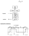
- einen Timer-Interrupt Ablauf zur PWM-Erzeugung.
- Figure 1 -
- a block diagram for the operation of a system according to the invention with proportional speed control and proportional grip force control;
- Figure 2 -
- a control loop for speed proportional operation;
- Figure 3 -
- a control loop for grip-proportional operation and
- Figure 4 -
- a timer interrupt process for PWM generation.
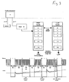
Gemäß Figur 1 werden zwei Elektrodensignale gemessen, gemittelt und einer Verriegelung zugeführt, die die Signale mit intern eingestellten Schaltschwellen vergleicht und die entsprechende Motorrichtung freigibt. Ein mechanischer Griffkraftschalter, dessen Schaltpunkt über dem Umschaltpunkt eines Automatikgetriebes liegt, trennt das System in zwei Regelkreise. Wird der Schaltpunkt nicht erreicht, so arbeitet das System mit proportionaler Geschwindigkeitsregelung (Figur 2); bei Überschreiten des Schaltpunktes wird auf proportionale Griffkraftregelung umgeschaltet (Figur 3).According to FIG. 1, two electrode signals are measured, averaged and fed to a lock which compares the signals with internally set switching thresholds and releases the corresponding motor direction. A mechanical grip switch, the switching point of which is above the switching point of an automatic transmission, separates the system into two control loops. If the switching point is not reached, the system works with proportional speed control (Figure 2); if the switching point is exceeded, a switch is made to proportional grip force control (FIG. 3).
Bei proportioner Geschwindigkeitsregelung ist der Griffkraftschalter geöffnet; gemäß Figur 1 wird die bevorzugte Elektrodenspannung mittels einer Tabelle in einen Drehzahlsollwert umgewandelt. Der entsprechende Tabellenwert stellt den Sollwert (Solldrehzahl) für den nachfolgenden Proportional-Integral-Regler (PI-Regler) dar. Durch diese Art der Tabellenumformung ist es möglich, eine Anpassung an eine bestimmte Elektrodensignal-Drehzahlcharakteristik vorzunehmen (Proportionalität). Dabei hat die Auswertung mit einer Tabelle den großen Vorteil, daß kleine Störungen des Eingangssignals durch die Umwandlung mit den Tabellenwerten einfach ausgeblendet werden (Filterung) und gleichzeitig individuelle Charakteristiken erzeugt werden können.With proportional speed control, the grip switch is open; According to FIG. 1, the preferred electrode voltage is converted into a speed setpoint using a table. The corresponding table value represents the setpoint (setpoint speed) for the subsequent proportional-integral controller (PI controller). This type of table conversion makes it possible to adapt to a specific electrode signal speed characteristic (proportionality). The evaluation with a table has the great advantage that small disturbances of the input signal by the Conversion with the table values can simply be hidden (filtering) and at the same time individual characteristics can be generated.
Der jetzt entstandene Sollwert wird mit der gemessenen Istdrehzahl des Motors verglichen und als Regeldifferenz einem PI-Regler zugeführt. Die Motordrehzahl wird in der PWM-Lücke als rückgekoppelte Generatorspannung gemessen. Im PI-Regler wird die Regelabweichung entsprechend eingestellter Parameter in ein PWM-Signal umgewandelt und damit die Motorbrücke angesteuert.The resulting setpoint is compared with the measured actual engine speed and fed to a PI controller as a control difference. The engine speed is measured in the PWM gap as a feedback generator voltage. In the PI controller, the control deviation is converted into a PWM signal in accordance with the set parameters and the motor bridge is thus controlled.
Der Regelkreis ist dadurch geschlossen. Der Motor dreht sich jetzt mit einer der aktuellen Elektrodenspannung proportionalen Drehzahl.This closes the control loop. The motor now rotates at a speed proportional to the current electrode voltage.
In einem überlagerten Steuerkreis wird der gemessene aktuelle Motorstromwert mit einem Strommaximum verglichen. Bei dessen Überschreiten (die Hand fährt in AUF-Richtung auf Anschlag) wird der PI-Regler und damit die Motorbrücke abgeschaltet.The measured current motor current value is compared with a current maximum in a superimposed control circuit. If it is exceeded (the hand moves in the UP direction to the stop), the PI controller and thus the motor bridge are switched off.
Wird hingegen der Griffkraftschalter durch Überschreiten der eingestellten Griffkraft betätigt, erfolgt eine Umschaltung auf eine proportionale Griffkraftregelung. Der Griffkraftaufbau erfolgt schrittweise, wobei die maximale Griffkraft in Stufen unterteilt ist. Dabei entspricht die aktuelle Elektrodenspannung einer bestimmten Stufenanzahl. Ein programminterner Zähler beginnt zwei Tabellen (PWM-Wert und dazugehörender Stromabschaltwert) vom Zählerstand 0 bis zu der von der aktuellen Elektrodenspannung vorgegebenen Stufenanzahl hochzuzählen. Der vom Zähler angewählte PWM-Wert wird ausgegeben. Parallel dazu wird der Motorstrom gemessen und mit dem zum PWM-Wert äquivalenten Stromabschaltwert verglichen. Bei Erreichen dieses Abschaltwertes wird der Zähler um 1 erhöht und der nächste PWM-Wert ausgegeben.If, on the other hand, the grip force switch is operated by exceeding the set grip force, the system switches over to proportional grip force control. The grip strength is built up gradually, with the maximum grip force being divided into steps. The current electrode voltage corresponds to a certain number of steps. An internal program counter starts counting up two tables (PWM value and associated current cut-off value) from the counter reading 0 to the number of steps specified by the current electrode voltage. The PWM value selected by the counter is output. In parallel, the motor current is measured and compared with the current cut-off value equivalent to the PWM value. When this switch-off value is reached, the counter is increased by 1 and the next PWM value is output.
Die kontinuierliche Ausgabe von ansteigenden PWM- und Stromabschaltwerten entspricht dem proportionalen Griffkraftaufbau.The continuous output of increasing PWM and current cut-off values corresponds to the proportional grip strength build-up.
Erreicht der Zähler die von der Elektrode vorgegebene Stufenanzahl, so ist die vorgegebene Griffkraft erreicht; der Motor wird abgeschaltet. Die Amplitude der Elektrodenspannung wird abgespeichert und als Schaltschwelle für ein eventuelles Nachgreifen der Hand festgelegt. Hierfür muß der Muskel entsprechend stärker angespannt werden, um diese Schaltschwelle zu überschreiten.If the counter reaches the number of steps specified by the electrode, the specified grip force is reached; the engine is switched off. The amplitude of the electrode voltage is saved and set as a switching threshold for a possible hand grip. For this purpose, the muscle must be tightened accordingly to exceed this switching threshold.
Um ein schnelles Zugreifen auf maximale Griffkraft zu ermöglichen, wird bei der Überschreitung einer vorgegebenen Schaltschwelle durch die Elektrodenspannung der Zählerstand nicht auf 0, sondern auf einen höheren Tabellenwert gestellt. Damit wird die maximale Griffkraft in kürzerer Zeit erreicht und der Motor abgeschaltet.In order to enable quick access to maximum grip force, the counter reading is not set to 0, but to a higher table value when a predetermined switching threshold is exceeded due to the electrode voltage. This means that the maximum grip force is reached in less time and the motor is switched off.
Wird beim Griffkraftaufbau der Hand durch den aktuellen Motorstrom ein gewisser intern eingestellter Maximalstromwert überschritten, so wird der Motor ebenfalls abgeschaltet.If the current motor current exceeds a certain internally set maximum current value when the hand grips, the motor is also switched off.
Nachfolgend werden die Figuren 2 bis 4 im einzelnen erläutert:Figures 2 to 4 are explained in detail below:
- · Zwei durch Muskelaktivität erzeugte elektrische Signale (Myosignale) werden über Hautelektroden abgenommen, verstärkt, gefiltert, gleichgerichtet und gelangen als Signale E1 und E2 an die Schaltung.· Two electrical signals generated by muscle activity (myo signals) are taken from skin electrodes, amplified, filtered, rectified and reach the circuit as signals E1 and E2 .
- · Über AD1 und AD2 wird eine analog/digital Wandlung (8Bit) vorgenommen· An analog / digital conversion (8 bit) is carried out via AD1 and AD2
- · Die Werte gelangen über eine Mittelwertbildung (Mittelung) an eine Verriegelung (LOCK).· The values arrive at a lock ( LOCK ) via averaging .
-
· Mittelung:
- Aufgabe:
- Mittelwertbildung und Bereichsvergrößerung, indem nur durch die halbe Anzahl der summierten Werte dividiert wird.
- Durchführung:
- 128 Meßwerte/64 = digitaler Wert
- Task:
- Averaging and enlarging the range by dividing by only half the number of totalized values.
- Execution:
- 128 measured values / 64 = digital value
-
· LOCK:
- Aufgabe:
- Auswahl des aktiven Signals, Verriegelung des inaktiven Signals.
- Durchführung:
- Ruhe:
- Ist weder A noch B aktiv, wird gewartet bis eines der beiden über die Einschaltschwelle gelangt. Die Einschaltschwellen für die beiden Richtungen (Hand AUF/Hand ZU) sind verschieden:
Hand AUF: Es existiert eine fix vorgegebene Einschaltschwelle U ein -auf .
Hand ZU: Es existiert eine variable Einschaltschwelle U ein -zu deren Wert durch die Strom(Kraft)-proportionale Betriebsart beeinflußbar ist. - Aktiv:
- Hat eines der beiden Signale die Einschaltschwelle überschritten, so gilt es als aktives Signal bis es unter die fix vorgegebene Ausschaltschwelle U aus fällt und wieder der Zustand "Ruhe" eintritt.
In der "aktiven" Zeit ist das inaktive Signal gesperrt.
- Task:
- Selection of the active signal, locking of the inactive signal.
- Execution:
- Quiet:
- If neither A nor B is active, the system waits until one of the two crosses the switch-on threshold. The switch-on thresholds for the two directions ( hand OPEN / hand CLOSE ) are different:
Manual OPEN : There is a fixed switch-on threshold U on-up .
Hand TO: there is a switch-variable U is a -zu whose value by the current (power) -proportionale mode is influenced. - Active:
- Has one of the two signals exceeded the switch-on threshold, then it is considered active signal until it under the fixed predetermined switch-off threshold of U falls again and the state is "silence" occurs.
The inactive signal is blocked in the "active" time.
- · Ist weder A nich B aktiv (Zustand "Ruhe"), so wird über die Verzweigung STOP der Timer Interrupt (TIR) gesperrt (TIR locked), das heißt es wird die PWM-Erzeugung unterdrückt.· If neither A B Not active (state "silence"), then through the branch of the T STOP imer I nterrupt (TIR) locked (locked TIR), i.e. it is suppressed, the PWM generation.
- · Ist eines der beiden Signale aktiv, so wird Signalwert als Zeiger einer Tabelle (V-Tabelle) benutzt, die zu jedem Signalwert einen Soll-Drehzahlwert für den Motor enthält.· If one of the two signals is active, the signal value is used as a pointer in a table ( V table ) which contains a setpoint speed value for the motor for each signal value.
- · Diese Soll-Drehzahl gilt als Eingangsgröße für den PI-Regler.· This target speed is the input variable for the PI controller .
-
· PI-Regler:
Es wird die Differenz aus der über AD3 gewandelten (Motor)Ist-Drehzahl und der Soll-Drehzahl gebildet (e).
The difference between the (engine) actual speed converted via AD3 and the target speed is formed (e). -
· PWM Begrenzung:
Systembedingt wird der Reglerausgang (k-Wert) nach oben und unten begrenzt, um eine einwandfreie Funktion der Regelung zu gewährleisten. PWM limitation:
Depending on the system, the controller output (k value) is limited upwards and downwards to ensure that the control functions properly. -
· TIR unlocked:
A oder B ist aktiv und ein PWM Tastverhältnis Wert wurde gebildet (k). Es kann also nun der TIR freigegeben werden (TIR unlocked). TIR unlocked:
A or B is active and a PWM duty cycle value has been formed (k). The TIR can now be released ( TIR unlocked ). -
· Der Motorostrom:
..wird über AD4 analog/digital gewandelt und in Mittelung auf I/4 geglättet. Es erfolgt eine adauernde Überprüfung des Motorstromes auf eine system-bedingte Stromkonstante I_max. Wird dieser Wert vom Motorstrom überschritten, so wird der TIR gesperrt (TIR locked)The motor current:
..is converted analog / digital via AD4 and smoothed to I / 4 averaging . The motor current is continuously checked for a system-related current constant I_max . If this value is exceeded by the motor current, the TIR is locked ( TIR locked )
Die Umschaltung in diese Betriebsart erfolgt durch einen Schalter (Griffkraftschalter), der durch seine konstruktive Ausführung des Zugreifen ab einer gewissen Kraftschwelle meldet (s=1). Der Ablauf in diesem Zustand soll eine Proportionalität zwischen Elektrodensignal und Griffkraft herstellen.
- · Wert B:
Da ein Kraftaufbau nur beim Schließen der Hand erfolgt, wird als Bezug für den gesamten Ablauf das Signal B (HAND ZU) genommen. - · Beschreibung der einzelenen Einsatzpunkte und Zeitwerte:
- 0 ... Griffkraftschalter geschlossen (s=1)
- 1 ... 60ms Pause (fix)
- 2 ... Erster Wert aus der PWM-Tabelle wird genommen und für 100ms ausgegeben
- 3.1 ... Strom I_ist wird gemessen und mit I_soll (aus I_soll-Tabelle) verglichen:
- a) I_ist > I_soll:
- TIR wird gesperrt.
- b) I_ist < I_soll:
- Messung von I_ist für maximal weitere 100ms. Tritt während dieser Zeit der unter a) beschriebene Fall nicht auf, so wird nach diesen 100ms TIR gesperrt
- 3.2 ... Unabhängig von I_soll wird I_ist kontinuierlich mit I_max verglichen. Wird I_max überschritten, so wird abgeschalten (TIR locked), um ein "Nachpumpen" zu verhindern. Entriegelt wird dieser Zustand nur durch Aktivierung von Signal A (Hand AUF).
- 4 ... TAB-Zeiger wird inkrementiert. (Die Werte in beiden Tabellen sind nummeriert
von 0 bis 18). Wenn TAB-Zeiger und B auf dieselbe Tabellennummer zeigen, ist die gewünschte Griffkraft erreicht und TIR kann gesperrt werden. Ist dieser Zustand noch nicht erreicht, so wird anPunkt 1 fortgefahren. Wurde dieser Zustand erreicht, so wird B gespeichert und als neue Einschaltschwelle bei LOCK verwendet. Dadurch verbleibt die Hand in diesem (gegriffenen) Zustand und kann nur durch
Aktivierung von A (HAND AUF) zu einem Verringern der Griffkraft bzw.
Aktivierung von B (Hand ZU) mit einem B-Wert, der höher als der zuletzt gespeicherte sein muß (neue Einschaltschwelle), zu einen Erhöhen der Griffkraft
aus dieser Stellung gebracht werden.
Tabellennummer 13 gesetzt.
Die ist nur gültig, wenn zich sum Zeitpunkt der Aktivierung der TAB-Zeiger unterhalb der Tabellennummer 13 befindet.
- · Value B:
Since the force is only built up when the hand is closed, signal B (HAND CLOSED) is used as a reference for the entire process. - Description of the individual operating points and current values:
- 0 ... handle switch closed (s = 1 )
- 1 ... 60ms break (fixed)
- 2 ... The first value from the PWM table is taken and output for 100ms
- 3.1 ... Current I_act is measured and compared with I_soll ( from I_soll table ):
- a) I_act > I_set :
- TIR is blocked.
- b) I_act < I_set :
- Measurement of I_act for a maximum of another 100ms. If the case described under a) does not occur during this time, TIR is blocked after these 100 ms
- 3.2 ... Regardless of I_setpoint , I_act is continuously compared with I_max . If I_max is exceeded, it is switched off ( TIR locked ) in order to prevent "post-pumping". This state is only unlocked by activating signal A ( manual OPEN ).
- 4 ... TAB pointer is incremented. (The values in both tables are numbered from 0 to 18). If the TAB pointer and B point to the same table number, the desired grip strength has been reached and TIR can be locked. If this condition has not yet been reached, continue with
point 1. If this state has been reached, B is saved and used as the new switch-on threshold for LOCK . As a result, the hand remains in this (gripped) state and can only by
Activation of A (HAND OPEN) to reduce grip strength or
Activation of B ( hand CLOSED ) with a B value that must be higher than the last one saved (new switch-on threshold) increases the grip force
be brought out of this position.
number 13 without ramping up to the corresponding value.
This is only valid if the TAB pointer is belowtable number 13 at the time of activation.
Sind die Bedingungen erfüllt, die zu einer Freigabe des TIR notwendig sind, so löst dieser 8 Bit Timer beim Übergang bon 255 auf 0 einen Interrupt aus, worauf in die Timer Interrupt Routine gesprungen wird, die der Erzeugung der PWM dient.
- · Reg.save [1]:
Da das Hauptprogramm an einer undefinierbaren Stelle (nur abhängig vom Auslaufen des Timers) unterbrochen wird, müssen die in Arbeit bedindlichen Werte abgespeichert werden. - · Kanalwahl/invert [2]:
Es wird eruiert, welcher der beiden Eingänge A oder B aktiv ist, um die aktuelle Motordrehrichtung festzustellen. Danach erfolgt die Invertierung des bis dahin ausgegebenen Motorsignales. - · t_ein/t_aus [3]:
Erkennung, ob man sich bei der Bildung des PWM im Zustand "Motor ein" oder "Motor aus" befindet. Entsprechend wird aus k der Wert für die Einschaltdauer (t_ein) oder die Ausschaltdauer (t_aus) bebildet. - · t->Timer [4]:
Der inPunkt 3 berechnete Zeitwert wird hier in den Timer geladen und dieser gestartet. Dies ergibt das eigentliche Tastverhältnis. - · Reg.recall [5]:
Die zu Beginn abgespeicherten Werte werden wieder aktiviert und der Hauptablauf fortgesetzt.
- · Reg.save [1]:
Since the main program is interrupted at an indefinable point (only depending on the expiry of the timer), the work-related values must be saved. - · Channel selection / invert [2]:
It is determined which of the two inputs A or B is active in order to determine the current direction of motor rotation. This is followed by the inversion of the motor signal output up to that point. - · T_ein / t_aus [3]:
Detection of whether one is in the "Motor on" or "Motor off" state when the PWM is formed. Correspondingly, the value for the switch-on time ( t_on ) or the switch-off time ( t_off ) is formed from k . - · T-> timer [4]:
The time value calculated inpoint 3 is loaded into the timer and this is started. This gives the actual duty cycle. - · Reg.recall [5]:
The values saved at the beginning are reactivated and the main process continues.
Claims (6)
Applications Claiming Priority (2)
| Application Number | Priority Date | Filing Date | Title |
|---|---|---|---|
| DE4416509A DE4416509C1 (en) | 1994-05-10 | 1994-05-10 | Process for the myoelectric control of an artificial limb |
| DE4416509 | 1994-05-10 |
Publications (3)
| Publication Number | Publication Date |
|---|---|
| EP0681818A2 true EP0681818A2 (en) | 1995-11-15 |
| EP0681818A3 EP0681818A3 (en) | 1995-11-29 |
| EP0681818B1 EP0681818B1 (en) | 2000-07-12 |
Family
ID=6517798
Family Applications (1)
| Application Number | Title | Priority Date | Filing Date |
|---|---|---|---|
| EP95105327A Expired - Lifetime EP0681818B1 (en) | 1994-05-10 | 1995-04-08 | Method to control an artifical limb by miopotentials |
Country Status (11)
| Country | Link |
|---|---|
| EP (1) | EP0681818B1 (en) |
| JP (2) | JPH0898853A (en) |
| CN (1) | CN1116855C (en) |
| AT (1) | ATE194477T1 (en) |
| AU (1) | AU1786695A (en) |
| CA (1) | CA2148577C (en) |
| DE (2) | DE4416509C1 (en) |
| DK (1) | DK0681818T3 (en) |
| ES (1) | ES2079337T3 (en) |
| RU (1) | RU2108768C1 (en) |
| TW (1) | TW241202B (en) |
Cited By (2)
| Publication number | Priority date | Publication date | Assignee | Title |
|---|---|---|---|---|
| WO1996041599A1 (en) * | 1995-06-13 | 1996-12-27 | Otto Bock Orthopädische Industrie Besitz- Und Verwaltungskommanditgesellschaft | Process for controlling the knee brake of a knee prosthesis and thigh prosthesis |
| CN116214511A (en) * | 2023-02-07 | 2023-06-06 | 南方科技大学 | Outer limb control method, device, electronic equipment and readable storage medium |
Families Citing this family (14)
| Publication number | Priority date | Publication date | Assignee | Title |
|---|---|---|---|---|
| CN1838933B (en) * | 2003-08-21 | 2010-12-08 | 国立大学法人筑波大学 | Wearable action-assist device, and method and program for controlling wearable action-assist device |
| DE102004048258A1 (en) | 2004-10-04 | 2006-04-20 | Trw Automotive Gmbh | Method and circuit arrangement for controlling an electric motor for a belt retractor |
| EP1955679B1 (en) | 2007-02-09 | 2013-11-06 | Semiconductor Energy Laboratory Co., Ltd. | Assist device |
| US10842653B2 (en) | 2007-09-19 | 2020-11-24 | Ability Dynamics, Llc | Vacuum system for a prosthetic foot |
| CN101305939B (en) * | 2008-05-26 | 2010-06-02 | 哈尔滨工业大学 | Electrical stimulator for sensation feedback of human-emulated myoelectric artificial hand |
| US8574178B2 (en) | 2009-05-26 | 2013-11-05 | The Hong Kong Polytechnic University | Wearable power assistive device for helping a user to move their hand |
| EP2474291A1 (en) * | 2009-09-02 | 2012-07-11 | Luis Armando Bravo Castillo | System and method for acquiring and processing myoelectric signals in order to control a prosthetic arm |
| CN101766510B (en) * | 2009-12-18 | 2012-02-01 | 东南大学 | Force touch sensation feedback and force intensity control method of mechanical artificial hand based on myoelectric control |
| CN102883689B (en) | 2010-05-06 | 2015-06-03 | 因文康公司 | Grasping aid device including a tool and an attaching of the tool |
| DK177559B1 (en) * | 2012-11-29 | 2013-10-14 | Invencon Aps | Aid grabbing tool with force activated gripping function |
| RU2627818C1 (en) | 2016-03-15 | 2017-08-11 | Сергей Игоревич Щукин | Method of bionic control of technical devices |
| CN105877745B (en) * | 2016-03-29 | 2018-06-26 | 东北大学 | Speed Regulation System Based on DC Motor and method based on surface electromyogram signal |
| RU2677787C1 (en) * | 2017-12-26 | 2019-01-21 | Общество с ограниченной ответственностью "Битроникс" | Method for managing devices |
| CN113262088B (en) * | 2021-05-27 | 2022-08-02 | 山东大学 | Multi-degree-of-freedom hybrid control artificial hand with force feedback and control method |
Citations (3)
| Publication number | Priority date | Publication date | Assignee | Title |
|---|---|---|---|---|
| US3418662A (en) * | 1965-03-31 | 1968-12-31 | Nat Res Dev | Prosthetic hand with improved control system for activation by electromyogram signals |
| DE2518854A1 (en) * | 1974-05-27 | 1975-12-18 | Opt Ges Fuer Orthopaedietechni | Economy circuit for myoelectrically controlled hand prosthesis - has motor which cuts out after performing movement |
| GB2098489A (en) * | 1981-05-15 | 1982-11-24 | Hodgson Dr John Ashworth | Signal processing apparatus |
Family Cites Families (5)
| Publication number | Priority date | Publication date | Assignee | Title |
|---|---|---|---|---|
| AT283586B (en) * | 1967-12-29 | 1970-08-10 | Viennatone Hoergeraete Ing Koe | Myoelectric control circuit for proportionally controlled electromotive operated artificial limbs |
| AT314075B (en) * | 1971-07-30 | 1974-03-25 | Viennatone Hoergeraete | Myoelectric control circuit |
| AT323317B (en) * | 1972-11-08 | 1975-07-10 | Viennatone Hoergeraete | MYOELECTRIC CONTROL CIRCUIT |
| AT340039B (en) * | 1975-09-18 | 1977-11-25 | Viennatone Gmbh | MYOELECTRIC CONTROL CIRCUIT |
| CN85100043B (en) * | 1985-04-01 | 1985-09-10 | 清华大学 | An automatic drive mechanism with changing speed and increasing grasp force used for prosthetic hand |
-
1994
- 1994-05-10 DE DE4416509A patent/DE4416509C1/en not_active Expired - Fee Related
- 1994-07-01 TW TW083105997A patent/TW241202B/en not_active IP Right Cessation
-
1995
- 1995-04-08 EP EP95105327A patent/EP0681818B1/en not_active Expired - Lifetime
- 1995-04-08 DE DE59508553T patent/DE59508553D1/en not_active Expired - Lifetime
- 1995-04-08 DK DK95105327T patent/DK0681818T3/en active
- 1995-04-08 ES ES95105327T patent/ES2079337T3/en not_active Expired - Lifetime
- 1995-04-08 AT AT95105327T patent/ATE194477T1/en active
- 1995-05-03 CA CA002148577A patent/CA2148577C/en not_active Expired - Lifetime
- 1995-05-03 AU AU17866/95A patent/AU1786695A/en not_active Abandoned
- 1995-05-06 RU RU95107479A patent/RU2108768C1/en active
- 1995-05-08 JP JP7109846A patent/JPH0898853A/en active Pending
- 1995-05-09 CN CN95105468A patent/CN1116855C/en not_active Expired - Lifetime
-
2005
- 2005-08-08 JP JP2005230161A patent/JP3923987B2/en not_active Expired - Fee Related
Patent Citations (3)
| Publication number | Priority date | Publication date | Assignee | Title |
|---|---|---|---|---|
| US3418662A (en) * | 1965-03-31 | 1968-12-31 | Nat Res Dev | Prosthetic hand with improved control system for activation by electromyogram signals |
| DE2518854A1 (en) * | 1974-05-27 | 1975-12-18 | Opt Ges Fuer Orthopaedietechni | Economy circuit for myoelectrically controlled hand prosthesis - has motor which cuts out after performing movement |
| GB2098489A (en) * | 1981-05-15 | 1982-11-24 | Hodgson Dr John Ashworth | Signal processing apparatus |
Cited By (3)
| Publication number | Priority date | Publication date | Assignee | Title |
|---|---|---|---|---|
| WO1996041599A1 (en) * | 1995-06-13 | 1996-12-27 | Otto Bock Orthopädische Industrie Besitz- Und Verwaltungskommanditgesellschaft | Process for controlling the knee brake of a knee prosthesis and thigh prosthesis |
| CN116214511A (en) * | 2023-02-07 | 2023-06-06 | 南方科技大学 | Outer limb control method, device, electronic equipment and readable storage medium |
| CN116214511B (en) * | 2023-02-07 | 2024-04-16 | 南方科技大学 | Outer limb control method, device, electronic equipment and readable storage medium |
Also Published As
| Publication number | Publication date |
|---|---|
| JPH0898853A (en) | 1996-04-16 |
| EP0681818B1 (en) | 2000-07-12 |
| RU2108768C1 (en) | 1998-04-20 |
| CN1117839A (en) | 1996-03-06 |
| JP3923987B2 (en) | 2007-06-06 |
| RU95107479A (en) | 1997-02-10 |
| DE4416509C1 (en) | 1995-11-23 |
| ES2079337T1 (en) | 1996-01-16 |
| ES2079337T3 (en) | 2000-12-01 |
| JP2005334675A (en) | 2005-12-08 |
| CA2148577A1 (en) | 1995-11-11 |
| AU1786695A (en) | 1995-11-16 |
| EP0681818A3 (en) | 1995-11-29 |
| ATE194477T1 (en) | 2000-07-15 |
| DE59508553D1 (en) | 2000-08-17 |
| CA2148577C (en) | 2007-01-09 |
| DK0681818T3 (en) | 2000-09-18 |
| TW241202B (en) | 1995-02-21 |
| CN1116855C (en) | 2003-08-06 |
Similar Documents
| Publication | Publication Date | Title |
|---|---|---|
| EP0681818B1 (en) | Method to control an artifical limb by miopotentials | |
| DE2751743C2 (en) | Method and control device for metering flowing media | |
| EP0081630B1 (en) | Electric gas pedal | |
| EP0296444B1 (en) | Speed control circuit for a dc miniature motor | |
| EP0705482B1 (en) | Switching contactor driving circuitry | |
| EP2171739B1 (en) | Control apparatus for a switching device with a pull-in coil and/or a holding coil and method for controlling the current flowing through the coil | |
| EP2850725B1 (en) | Method for controlling a power source, and power source and process controller therefor | |
| DE3045996A1 (en) | Electro-surgical scalpel instrument - has power supply remotely controlled by surgeon | |
| CH641905A5 (en) | PRESSURE CONTROL DEVICE FOR PNEUMATIC PRESSURES, ESPECIALLY IN VEHICLES. | |
| EP0448798A1 (en) | Electrosurgical unit | |
| EP1880096B1 (en) | Method and device for electrically actuating a valve with a mechanical closing element | |
| DE102004045568A1 (en) | Control and / or regulating device for an electric motor-operated adjusting device for adjusting, preferably for translational displacement, at least one furniture part | |
| EP3226264B1 (en) | Power control with a dither signal | |
| DE3343883A1 (en) | Method and device for two-point control of a load current | |
| DE2710049C2 (en) | Ultrasonic dental treatment device | |
| EP0014369A1 (en) | Pressure control system for pneumatic vehicle brakes, in particular of rail vehicles | |
| EP3381119B1 (en) | Method for controlling the current of an inductive load | |
| EP3672053A1 (en) | Control method for a dual active bridge series resonant converter and dual active bridge series resonant converter operating on the basis of this method | |
| WO2003038968A1 (en) | Method for monitoring the reversing process of electrically actuatable units | |
| DE2731501C3 (en) | Control arrangement for a direct current motor operated with series connection-shunt switching | |
| EP0848309B1 (en) | Device for monitoring and limiting the static closing force of a door | |
| EP0678271A2 (en) | Circuit for controlling the suction capacity of a vacuum cleaner | |
| EP0678971B1 (en) | Method of reversing the direction of rotation for a brushless DC motor from full speed and brushless DC motor | |
| DE3824547A1 (en) | Motor control with switchover to manual operation | |
| EP0498202B1 (en) | Electropneumatic position controller |
Legal Events
| Date | Code | Title | Description |
|---|---|---|---|
| PUAI | Public reference made under article 153(3) epc to a published international application that has entered the european phase |
Free format text: ORIGINAL CODE: 0009012 |
|
| PUAL | Search report despatched |
Free format text: ORIGINAL CODE: 0009013 |
|
| AK | Designated contracting states |
Kind code of ref document: A2 Designated state(s): AT BE CH DE DK ES FR GB IT LI NL SE |
|
| AK | Designated contracting states |
Kind code of ref document: A3 Designated state(s): AT BE CH DE DK ES FR GB IT LI NL SE |
|
| ITCL | It: translation for ep claims filed |
Representative=s name: MODIANO & ASSOCIATI S.R.L. |
|
| GBC | Gb: translation of claims filed (gb section 78(7)/1977) | ||
| EL | Fr: translation of claims filed | ||
| REG | Reference to a national code |
Ref country code: ES Ref legal event code: BA2A Ref document number: 2079337 Country of ref document: ES Kind code of ref document: T1 |
|
| 17P | Request for examination filed |
Effective date: 19951221 |
|
| TCNL | Nl: translation of patent claims filed | ||
| 17Q | First examination report despatched |
Effective date: 19980603 |
|
| GRAG | Despatch of communication of intention to grant |
Free format text: ORIGINAL CODE: EPIDOS AGRA |
|
| GRAG | Despatch of communication of intention to grant |
Free format text: ORIGINAL CODE: EPIDOS AGRA |
|
| GRAH | Despatch of communication of intention to grant a patent |
Free format text: ORIGINAL CODE: EPIDOS IGRA |
|
| GRAH | Despatch of communication of intention to grant a patent |
Free format text: ORIGINAL CODE: EPIDOS IGRA |
|
| GRAA | (expected) grant |
Free format text: ORIGINAL CODE: 0009210 |
|
| AK | Designated contracting states |
Kind code of ref document: B1 Designated state(s): AT BE CH DE DK ES FR GB IT LI NL SE |
|
| REF | Corresponds to: |
Ref document number: 194477 Country of ref document: AT Date of ref document: 20000715 Kind code of ref document: T |
|
| REG | Reference to a national code |
Ref country code: CH Ref legal event code: NV Representative=s name: BRAUN & PARTNER PATENT-, MARKEN-, RECHTSANWAELTE Ref country code: CH Ref legal event code: EP |
|
| GBT | Gb: translation of ep patent filed (gb section 77(6)(a)/1977) |
Effective date: 20000714 |
|
| REF | Corresponds to: |
Ref document number: 59508553 Country of ref document: DE Date of ref document: 20000817 |
|
| ET | Fr: translation filed | ||
| REG | Reference to a national code |
Ref country code: DK Ref legal event code: T3 |
|
| ITF | It: translation for a ep patent filed | ||
| REG | Reference to a national code |
Ref country code: ES Ref legal event code: FG2A Ref document number: 2079337 Country of ref document: ES Kind code of ref document: T3 |
|
| PLBE | No opposition filed within time limit |
Free format text: ORIGINAL CODE: 0009261 |
|
| STAA | Information on the status of an ep patent application or granted ep patent |
Free format text: STATUS: NO OPPOSITION FILED WITHIN TIME LIMIT |
|
| 26N | No opposition filed | ||
| REG | Reference to a national code |
Ref country code: GB Ref legal event code: IF02 |
|
| PGFP | Annual fee paid to national office [announced via postgrant information from national office to epo] |
Ref country code: BE Payment date: 20050421 Year of fee payment: 11 |
|
| PGFP | Annual fee paid to national office [announced via postgrant information from national office to epo] |
Ref country code: DK Payment date: 20050426 Year of fee payment: 11 |
|
| PGFP | Annual fee paid to national office [announced via postgrant information from national office to epo] |
Ref country code: CH Payment date: 20050503 Year of fee payment: 11 |
|
| PG25 | Lapsed in a contracting state [announced via postgrant information from national office to epo] |
Ref country code: LI Free format text: LAPSE BECAUSE OF NON-PAYMENT OF DUE FEES Effective date: 20060430 Ref country code: CH Free format text: LAPSE BECAUSE OF NON-PAYMENT OF DUE FEES Effective date: 20060430 Ref country code: BE Free format text: LAPSE BECAUSE OF NON-PAYMENT OF DUE FEES Effective date: 20060430 |
|
| PG25 | Lapsed in a contracting state [announced via postgrant information from national office to epo] |
Ref country code: DK Free format text: LAPSE BECAUSE OF NON-PAYMENT OF DUE FEES Effective date: 20060501 |
|
| REG | Reference to a national code |
Ref country code: DK Ref legal event code: EBP |
|
| REG | Reference to a national code |
Ref country code: CH Ref legal event code: PL |
|
| BERE | Be: lapsed |
Owner name: OTTO *BOCK ORTHOPADISCHE INDUSTRIE BESITZ- UND VER Effective date: 20060430 |
|
| PGFP | Annual fee paid to national office [announced via postgrant information from national office to epo] |
Ref country code: GB Payment date: 20140423 Year of fee payment: 20 |
|
| PGFP | Annual fee paid to national office [announced via postgrant information from national office to epo] |
Ref country code: DE Payment date: 20140430 Year of fee payment: 20 Ref country code: NL Payment date: 20140417 Year of fee payment: 20 Ref country code: ES Payment date: 20140417 Year of fee payment: 20 Ref country code: SE Payment date: 20140423 Year of fee payment: 20 Ref country code: IT Payment date: 20140424 Year of fee payment: 20 Ref country code: AT Payment date: 20140417 Year of fee payment: 20 Ref country code: FR Payment date: 20140416 Year of fee payment: 20 |
|
| REG | Reference to a national code |
Ref country code: DE Ref legal event code: R071 Ref document number: 59508553 Country of ref document: DE |
|
| REG | Reference to a national code |
Ref country code: NL Ref legal event code: V4 Effective date: 20150408 |
|
| REG | Reference to a national code |
Ref country code: NL Ref legal event code: V4 Effective date: 20150408 |
|
| REG | Reference to a national code |
Ref country code: GB Ref legal event code: PE20 Expiry date: 20150407 |
|
| REG | Reference to a national code |
Ref country code: AT Ref legal event code: MK07 Ref document number: 194477 Country of ref document: AT Kind code of ref document: T Effective date: 20150408 |
|
| REG | Reference to a national code |
Ref country code: SE Ref legal event code: EUG |
|
| REG | Reference to a national code |
Ref country code: ES Ref legal event code: FD2A Effective date: 20150626 |
|
| PG25 | Lapsed in a contracting state [announced via postgrant information from national office to epo] |
Ref country code: ES Free format text: LAPSE BECAUSE OF EXPIRATION OF PROTECTION Effective date: 20150409 Ref country code: GB Free format text: LAPSE BECAUSE OF EXPIRATION OF PROTECTION Effective date: 20150407 |