EP0680903B1 - Bogen Vereinzelungs- und Zuführungssystem - Google Patents
Bogen Vereinzelungs- und Zuführungssystem Download PDFInfo
- Publication number
- EP0680903B1 EP0680903B1 EP95302416A EP95302416A EP0680903B1 EP 0680903 B1 EP0680903 B1 EP 0680903B1 EP 95302416 A EP95302416 A EP 95302416A EP 95302416 A EP95302416 A EP 95302416A EP 0680903 B1 EP0680903 B1 EP 0680903B1
- Authority
- EP
- European Patent Office
- Prior art keywords
- pick
- pick roller
- media sheet
- rotation
- feed
- Prior art date
- Legal status (The legal status is an assumption and is not a legal conclusion. Google has not performed a legal analysis and makes no representation as to the accuracy of the status listed.)
- Expired - Lifetime
Links
- 230000008878 coupling Effects 0.000 claims 2
- 238000010168 coupling process Methods 0.000 claims 2
- 238000005859 coupling reaction Methods 0.000 claims 2
- 230000037431 insertion Effects 0.000 claims 1
- 238000003780 insertion Methods 0.000 claims 1
- 238000013459 approach Methods 0.000 description 2
- 238000012986 modification Methods 0.000 description 2
- 230000004048 modification Effects 0.000 description 2
- 230000003068 static effect Effects 0.000 description 2
- 230000007423 decrease Effects 0.000 description 1
- 230000003247 decreasing effect Effects 0.000 description 1
- 238000010586 diagram Methods 0.000 description 1
- 230000000694 effects Effects 0.000 description 1
- 239000000463 material Substances 0.000 description 1
- 230000003287 optical effect Effects 0.000 description 1
Images

Classifications
-
- B—PERFORMING OPERATIONS; TRANSPORTING
- B65—CONVEYING; PACKING; STORING; HANDLING THIN OR FILAMENTARY MATERIAL
- B65H—HANDLING THIN OR FILAMENTARY MATERIAL, e.g. SHEETS, WEBS, CABLES
- B65H3/00—Separating articles from piles
- B65H3/02—Separating articles from piles using friction forces between articles and separator
- B65H3/06—Rollers or like rotary separators
- B65H3/0684—Rollers or like rotary separators on moving support, e.g. pivoting, for bringing the roller or like rotary separator into contact with the pile
-
- B—PERFORMING OPERATIONS; TRANSPORTING
- B65—CONVEYING; PACKING; STORING; HANDLING THIN OR FILAMENTARY MATERIAL
- B65H—HANDLING THIN OR FILAMENTARY MATERIAL, e.g. SHEETS, WEBS, CABLES
- B65H3/00—Separating articles from piles
- B65H3/02—Separating articles from piles using friction forces between articles and separator
- B65H3/06—Rollers or like rotary separators
- B65H3/0615—Rollers or like rotary separators reciprocating and rotatable in one direction only
-
- B—PERFORMING OPERATIONS; TRANSPORTING
- B65—CONVEYING; PACKING; STORING; HANDLING THIN OR FILAMENTARY MATERIAL
- B65H—HANDLING THIN OR FILAMENTARY MATERIAL, e.g. SHEETS, WEBS, CABLES
- B65H3/00—Separating articles from piles
- B65H3/02—Separating articles from piles using friction forces between articles and separator
- B65H3/06—Rollers or like rotary separators
- B65H3/0669—Driving devices therefor
Definitions
- This invention relates to media sheet feeders, and more particularly, to a media sheet pick and feed system that obviates the need for a spring loaded media sheet tray and enables easy re-loading of a media sheet tray.
- a commonly used prior art mechanism for picking and feeding of media sheets employs a D-shaped wheel which is rotated to cause a media sheet pick action.
- the flat section of the D-wheel remains out-of-contact with the fed sheet.
- This arrangement is satisfactory so long as the media sheet, during a feed operation, is not bent around the D-wheel shaft. This may occur when the media tray is positioned at an angle to the feed mechanism. Under such a circumstance, the media sheet must bend as it is fed into the print mechanism. If the media sheet presses against the D-shaped wheel, significant drag on the media sheet results.
- a solution to this problem has been to affix a pair of free-wheeling disks to the same shaft on which the D-wheel is mounted.
- FIG. 1 is a side view of the Epson pick wheel and comprises a drive gear 10 that is mounted on a shaft 12 which is, in turn, coupled to a drive motor (not shown).
- a pivot arm 14 is mounted for rotation about shaft 12 and encloses a rubber pick roller 16.
- a driven gear 18 mates with drive gear 10, is rigidly connected to rubber pick roller 16, and is mounted for rotation on a shaft 20.
- a spring washer 22 is positioned between an inner surface of arm 14 and driven gear 18 and performs a friction clutch function.
- a media tray includes a pressure plate 24 which supports a stack of media sheets 26 and is biased by a spring 28 into contact with rubber pick roller 16.
- An edge separator 30 is positioned to maintain an uppermost sheet on stack 26 in place until operation of rubber pick roller 16.
- drive gear 10 is driven in a counter clockwise (CCW) direction thereby causing driven gear 18 to rotate in a clockwise (CW) direction.
- CW clockwise
- arm 14 and pick roller 16 are caused to rotate in a CCW direction until arm 14 hits a stop 32.
- This action causes pick roller 16 to come into contact with an uppermost sheet of stack 26, which uppermost sheet is, in turn, forced against pick roller 16 through the action of spring 28 on tray 24.
- Continued clockwise rotation of pick roller 16 causes a feed of an uppermost sheet 34 from stack 26.
- the use of a spring loaded tray may require that the media sheet tray be removed for media sheet reloading or that a camming mechanism be provided that depresses the pressure plate to enable reloading.
- the camming mechanism increases torque requirements on the mechanism drive motor.
- US-A-4934686 describes a media sheet pick and feed system as defined by the preamble to Claim 1.
- a one-way clutch mechanism is coupled between the pick roller shaft and the pick roller means, the arrangement being such that rotation of the pick roller shaft in one sense is transmitted by the clutch means to the pick roller means, but rotation of the pick roller shaft in the opposite sense is not so transmitted.
- reverse rotation of the pick roller shaft causes the arm means to rotate about the pick roller shaft so as to raise the pick roller means to a position above the uppermost media sheet and not in contact therewith.
- Such an arrangement is stated in this Patent Specification to be so as to ease handling of the cut sheet.
- Fig. 1 is a side view of a prior art pick roller mechanism.
- Fig. 2 is a schematic side view of the pick roller mechanism of Fig. 1 during a pick action.
- Fig. 3 is a schematic side view of the pick roller mechanism of Fig. 1 after the pick action and during a sheet feed.
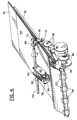
- Fig. 4 is a perspective view of a media sheet pick and feed system incorporating the invention hereof and illustrating a pick action.
- Fig. 5 is a front view of a clutch mechanism employed to drive a pick roller shaft in the system of Fig. 4.
- Fig. 6 is a side view of the clutch mechanism shown in Fig. 5.
- Fig. 7 is a force diagram illustrating a force feedback action which occurs during the operation of the pick roller shown in Fig. 4.
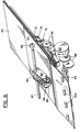
- Fig. 8 is a perspective view of the mechanism of Fig. 4 after a pick action has been accomplished and when a media sheet is being fed by feed rollers.
- a stack of media sheets 50 is supported on a tray 52 which is slidably removable from and insertable into a print mechanism. Tray 52 may be replenished with media sheets without removal from the print mechanism. Tray 52, when in position within the print mechanism, rests in a stationary position and includes no spring means for biasing stack 50 against the picking and feeding apparatus.
- a pair of arms 58 and 60 extend from and are mounted for rotation about a pick roller shaft 62. Arms 58 and 60 are connected (not shown) so as to always move in tandem.
- a pick roller drive gear 64 is rigidly mounted to pick roller shaft 62 and, through a pair of idler rollers 66, engages a gear (not shown) that is rigidly coupled to pick roller 56. Arms 58 and 60 enable pick roller 56 to rest on the topmost media sheet 54 of stack 50.
- the outer surface of pick roller 56 is preferably comprised of a rubber or a rubber-like material. As the size of stack 50 either increases or decreases, arms 58 and 60 rotate about pick roller shaft 62 and maintain pick roller 56 in constant contact with an uppermost sheet 54.
- a drive gear 68 that engages a friction clutch mechanism comprising gears 70, 72 and arm 74.
- a side view of the clutch mechanism (as seen from below tray 52) is shown in Fig. 5 and a plan view in Fig. 6.
- Gear 72 is mounted on a shaft 76 that extends from a fixed wall position (not shown) in Fig. 4.
- Gear 70 is connected to arm 74 via a shaft 78.
- a spring 80 is positioned between gear 70 and arm 74 so as to provide a frictional clutching operation.
- a motor 90 when driven CCW, operates through idler gears 92 to drive gear 72 in a CCW direction.
- Gear 70 is thus caused to rotate in a CW direction, causing gear 68 and pick rotor shaft 62 to rotate in a CCW direction. That rotary motion is transferred via gear 64 and idler gears 66 and causes pick roller 56 to rotate in the CW direction. Because arms 58 and 60 are rotatably mounted on pick roller shaft 62, pick roller 56 rests on uppermost sheet 54 of stack 50.
- the CW rotation of pick roller 56 causes media sheet 54 to move in a leftward direction towards feed rollers 94.
- the CCW movement of motor 90 is transmitted to feed rollers 94 through idler gears 96 and feed roller drive gear 98.
- Feed roller drive gear 98 and feed rollers 94 rotate in a CW direction.
- the CW rotation of feed rollers 94 prevents the passage of media sheet 54 therethrough.
- media sheet 54 is pushed against the nip between feed rollers 94 and pinch rollers 100, thus causing a transverse alignment action to be imparted to media sheet 54.
- a feature of the invention is that the arrangement of pick roller 56 in relation to topmost media sheet 54 enables a force feedback action which causes the normal force between pick roller 56 and media sheet 54 to increase so long as media sheet 54 resists travel in the feed direction.
- This feature can be understood by referring to Fig. 7 wherein pick roller 56 is shown engaging an uppermost surface of media sheet 54.
- f d u ⁇ N
- u the coefficient of friction between pick roller 56 and media sheet 54
- N the normal force acting between pick roller 56 and media sheet 54.
- N is small and fd is too small to overcome the resistance of media sheet 54.
- An increase in N results in an increase in the maximum driving force available f dmax . This allows f d to continue to increase until a point is reached where it is large enough to overcome the resistance of media sheet 54.
- the force feedback effect varies as the height of pick roller 56 changes with changes in the size of stack 50. This is because moment arm h changes with height of stack 50. Nevertheless, so long as h > 0 and pick roller 56 contacts media sheet 54 downstream in the feed direction from pick roller shaft 62, the normal force feedback action occurs.
- pick roller 56 will contact tray 52. If a pick action is initiated, large forces can be generated between pick roller 56 and tray 52 which can cause motor 90 to stall or may cause parts in the pick mechanism to break. This situation must be avoided.
- an optical sensor may be used to sense paper in the tray in order to prevent an attempt to pick from an empty tray.
- Another approach is to place an idler roller in the bottom of tray 52, underneath pick roller 56. The idler roller will then rotate with pick roller 56 during any attempt to pick from an empty tray 52, thereby limiting the forces generated by pick roller 56 to the level required to turn the idler roller.
- a feed operation will be described.
- media sheet 54 reaches the configuration shown in Fig. 4, the direction of rotation of motor 90 is changed to a CW direction.
- the CW rotation is transmitted via idler gears 92 and causes a CW rotation of gear 72.
- arm 74 rotates in a CW direction out of engagement with gear 68.
- Arm 74 is limited in its clockwise rotation by a stop (not shown).
- gear 70 from gear 68 allows pick roller shaft 62 to operate in a free-wheeling mode so that pick roller 56 is free to continue rotation in a CW direction while feed rollers 94 are rotated in a CCW direction by the drive action transmitted through idler gears 96 from motor 90. Because of the free wheeling action of pick roller 56, there is little resistance to travel of topmost media sheet 54 during the operation of feed rollers 94. As the height of stack 50 varies (both upwardly and downwardly) pick roller 56 is in contact with the uppermost sheet due to the rotation of arms 58 and 60 about pick roller shaft 62.
- the initial normal force exerted by pick roller 56 on an uppermost media sheet can be quite low, because the needed additional force during picking is generated if the sheet resists picking. This helps during the loading of additional sheets as pick roller 56 can be easily lifted by a stack of inserted papers.
- the low normal force also helps to reduce drag when the topmost sheet is being advanced by feed rollers 94.
- the system also enables the handling of a large range of paper weights due to its ability to generate an amount of normal force required in each case.
Landscapes
- Engineering & Computer Science (AREA)
- Mechanical Engineering (AREA)
- Sheets, Magazines, And Separation Thereof (AREA)
- Handling Of Sheets (AREA)
- Handling Of Cut Paper (AREA)
Claims (8)
- Ein Medienblatt-Aufnahme- und -Zuführ-System mit folgenden Merkmalen:einer Aufnahmerollenwelle (62), die für eine Drehung befestigt ist;einer Medienblattträgeroberfläche (52) zum Tragen eines Stapels (50) von Medienblättern während Aufnahme- und Zuführ-Operationen, wobei die Trägeroberfläche (52) von der Aufnahmerollenwelle (62) während der Operationen um einen festen Abstand getrennt ist;einer Armeinrichtung (58, 60), die mit der Aufnahmerollenwelle (62) gekoppelt ist und sich von derselben erstreckt;einer Aufnahmerolleneinrichtung (56, 64, 66), die von der Armeinrichtung (58, 60) drehbar getragen ist, um auf einem obersten Medienblatt (54) des Stapels (50) zu liegen, und die antriebsmäßig mit der Aufnahmerollenwelle (62) in Eingriff ist;einer Antriebseinrichtung (90, 92) mit einer ersten und einer zweiten Drehrichtung; undeiner Kupplungseinrichtung (68, 70, 72, 74) mit einem Antriebszustand und einem Nicht-Antriebszustand;
dadurch gekennzeichnet, daß die Kupplungseinrichtung (68, 70, 72, 74), wenn sie in dem Antriebszustand ist, angeordnet ist, um die Antriebseinrichtung (90, 92) mit der Aufnahmerollenwelle (62) zu koppeln, um eine Drehung derselben und eine Aufnahmedrehung der Aufnahmerolleneinrichtung (56, 64, 66) zu bewirken, wobei die Kupplungseinrichtung (68, 70, 72, 74) in dem Nicht-Antriebszustand von der Aufnahmerollenwelle (62) entkoppelt ist, um ein Freilaufen der Aufnahmerollenwelle 62 und der Aufnahmerolleneinrichtung (56, 64, 66) zu ermöglichen, während dieselbe immer noch in Kontakt mit einem Medienblatt (54), das zugeführt wird, ist. - Das Medienblatt-Aufnahme- und -Zuführ-System gemäß Anspruch 1, das ferner folgende Merkmale aufweist:eine Zuführrolleneinrichtung (94, 96, 98, 100), die in einer Zuführrichtung bezüglich der Aufnahmerolleneinrichtung (52, 64, 66) positioniert ist und mit der Antriebseinrichtung (90, 92) gekoppelt ist, während die Antriebseinrichtung (90, 92) in der ersten Drehrichtung gedreht wird, wobei dadurch bewirkt wird, daß sich die Zuführrolleneinrichtung (94, 96, 98, 100) dreht, um zu verhindern, daß ein Medienblatt (54) in einer Zuführrichtung bewegt wird, während die Aufnahmerolleneinrichtung (56, 64, 66) in einer Aufnahmerichtung gedreht wird, wobei die Zuführrolleneinrichtung (94, 96, 98, 100) und die Aufnahmerolleneinrichtung (56, 64, 66) zusammenarbeiten, um dadurch eine Ausrichtung des Medienblatts (54) gegen die Zuführrolleneinrichtung zu ermöglichen.
- Das Medienblatt-Aufnahme- und -Zuführ-System gemäß Anspruch 2, bei dem die Zuführrolleneinrichtung (94, 96, 98, 100) auf eine Drehung der Antriebseinrichtung (90, 92) in der zweiten Drehrichtung anspricht, um ein Medienblatt (54) in Ineingriffnahme mit derselben zuzuführen.
- Das Medienblatt-Aufnahme- und -Zuführ-System gemäß Anspruch 1, bei dem sich die Armeinrichtung (58, 60) von der Aufnahmerolleneinrichtung (56, 64, 66) in einer Richtung erstreckt, in der die Medienblätter zugeführt werden sollen, und bewirkt, daß die Aufnahmerolleneinrichtung (56, 64, 66) ein Medienblatt an einem Punkt in einer Zuführrichtung der Medienblätter strömungsmäßig hinter der Aufnahmerollenwelle (62) durchgehend kontaktiert.
- Das Medienblatt-Aufnahme- und -Zuführ-System gemäß Anspruch 3, bei dem die Armeinrichtung und die Aufnahmerolleneinrichtung folgende Merkmale aufweisen:ein Paar von Armen (58, 60), die mit der Aufnahmerollenwelle (62) drehbar gekoppelt sind;eine Aufnahmerolle (56), die auf einer Achse zwischen dem Paar von Armen (58, 60) an einem äußeren Ende derselben, das von der Aufnahmerollenwelle (62) am weitesten entfernt ist, befestigt ist; undeiner Getriebeeinrichtung (64, 66), die die Aufnahmerolle (56) antriebsmäßig mit der Aufnahmerollenwelle (62) koppelt.
- Das Medienblatt-Aufnahme- und -Zuführ-System gemäß Anspruch 5, bei dem die Kupplungseinrichtung (68, 70, 72, 74) folgende Merkmale aufweist:ein erstes Getrieberad (72), das mit der Antriebseinrichtung (90, 92) gekoppelt ist und an einem äußeren Ende eines Arms (74) durch eine feste Achse (76) befestigt ist;ein zweites Getrieberad (70), das an einer translatierbaren Achse (78), die an einem zweiten äußeren Ende des Arms (74) befestigt ist, reibungsmäßig befestigt ist, wobei eine Drehung des ersten Getrieberads (72) durch eine Drehung der Antriebseinrichtung (90, 92) in der ersten Richtung eine Bewegung des Arms (74) und des Zweiten Getrieberads (70) in eine antriebsmäßige Ineingriffnahme mit der Aufnahmerollenwelle (62) bewirkt, wobei eine Drehung des ersten Getrieberads (72) in einer entgegengesetzten Richtung durch die Antriebseinrichtung (90, 92) eine Bewegung des Arms (74) und des zweiten Getrieberads (70) aus der Ineingriffnahme mit der Aufnahmerollenwelle (62) bewirkt.
- Das Medienblatt-Aufnahme- und -Zuführ-System gemäß Anspruch 4, bei dem ein Stapel von Medienblättern (50) von der Medienblatträgeroberfläche (52) einführbar und entfernbar ist, während dieselbe mit dem MedienblattAufnahme- und -Zuführ-System in Eingriff ist, wobei ein Einführen des Stapels von Medienblättern (50) eine Drehung der Armeinrichtung (58, 60) und der Aufnahmerolleneinrichtung (56, 64, 66) um die Aufnahmerollenwelle (62) bewirkt.
- Das Medienblatt-Aufnahme- und -Zuführ-System gemäß Anspruch 5, das ferner folgendes Merkmal aufweist:eine Einrichtung zum Verhindern, daß die Aufnahmerolle (56) die Medienblatträgeroberfläche (52) während eines angetriebenen Drehzustands berührt.
Applications Claiming Priority (2)
| Application Number | Priority Date | Filing Date | Title |
|---|---|---|---|
| US23860194A | 1994-05-03 | 1994-05-03 | |
| US238601 | 1994-05-03 |
Publications (2)
| Publication Number | Publication Date |
|---|---|
| EP0680903A1 EP0680903A1 (de) | 1995-11-08 |
| EP0680903B1 true EP0680903B1 (de) | 1998-06-17 |
Family
ID=22898590
Family Applications (1)
| Application Number | Title | Priority Date | Filing Date |
|---|---|---|---|
| EP95302416A Expired - Lifetime EP0680903B1 (de) | 1994-05-03 | 1995-04-12 | Bogen Vereinzelungs- und Zuführungssystem |
Country Status (4)
| Country | Link |
|---|---|
| US (1) | US5547181A (de) |
| EP (1) | EP0680903B1 (de) |
| JP (1) | JP3590446B2 (de) |
| DE (1) | DE69502996T2 (de) |
Cited By (1)
| Publication number | Priority date | Publication date | Assignee | Title |
|---|---|---|---|---|
| US7059596B2 (en) | 2000-08-10 | 2006-06-13 | Brother Kogyo Kabushiki Kaisha | Sheet feeder |
Families Citing this family (53)
| Publication number | Priority date | Publication date | Assignee | Title |
|---|---|---|---|---|
| US5934045A (en) * | 1996-12-04 | 1999-08-10 | Privatizer Systems, Inc. | Method for providing confidentiality to a facsimile transmission having information associated with a first page of the transmission printed on a first enclosure sheet |
| US5941048A (en) * | 1996-12-04 | 1999-08-24 | Privatizer Systems, Inc | Apparatus and method of sealing an envelope in a document security apparatus |
| US5979148A (en) * | 1996-12-04 | 1999-11-09 | Privatizer Systems, Inc. | Apparatus and method for sealing an envelope in a document security apparatus having a sealing roller with a sealing ridge attached thereto |
| US5996317A (en) * | 1996-12-04 | 1999-12-07 | Privatizer Systems, Inc. | Method for providing confidentiality to a facsimile transmission having a non-printed back enclosure sheet |
| US5956930A (en) * | 1996-12-04 | 1999-09-28 | Privatizer Systems, Inc. | Apparatus and method of forming an envelope in a document security apparatus |
| US5946889A (en) * | 1996-12-04 | 1999-09-07 | Privatizer Systems, Inc | Apparatus and method for enclosing a confidential sheet between a first enclosure sheet and a second enclosure sheet within a document security apparatus |
| US5937619A (en) * | 1996-12-04 | 1999-08-17 | Privatizer Systems Incorporated | Apparatus and method for sealing an envelope having a first lateral side and a second lateral side in a document security apparatus |
| US6076336A (en) * | 1996-12-04 | 2000-06-20 | Privatizer Systems, Inc. | Apparatus and method for advancing a confidential sheet into a pocket defined by a number of enclosure sheets |
| US5887411A (en) * | 1996-12-04 | 1999-03-30 | Privatizer Systems, Inc. | Apparatus and method for positioning a number of non-transparent enclosure sheets in a document security apparatus |
| KR200168038Y1 (ko) * | 1996-12-27 | 2000-03-02 | 윤종용 | 용지 공급 장치 |
| US5868385A (en) * | 1997-03-17 | 1999-02-09 | Lexmark International, Inc. | Media feed arm with directional damping |
| JP2935262B1 (ja) * | 1998-03-20 | 1999-08-16 | 富士通株式会社 | シート供給装置及びそれを用いた記録装置 |
| US6267369B1 (en) * | 1999-07-02 | 2001-07-31 | Hewlett-Packard Company | Torque loading of a sheet material feed roller |
| US6217018B1 (en) * | 1999-07-22 | 2001-04-17 | Hewlett-Packard Company | Sheet feed mechanism |
| US6170348B1 (en) * | 1999-09-13 | 2001-01-09 | Hewlett-Packard Company | Swing arm transmission for driving sheet feed mechanism of a printing device media input tray |
| US6322065B1 (en) * | 1999-12-22 | 2001-11-27 | Hewlett-Packard Company | Hinged-arm pick mechanism |
| US6464414B1 (en) | 2000-03-21 | 2002-10-15 | Lexmark International, Inc. | Print media sensor adjustment mechanism |
| US6382619B1 (en) * | 2000-04-19 | 2002-05-07 | Hewlett-Packard Company | Pick mechanism and image forming device including the same |
| US6352256B1 (en) * | 2000-07-12 | 2002-03-05 | Acer Communications And Multimedia Inc. | Media feeding system |
| US6457707B1 (en) | 2000-11-22 | 2002-10-01 | Hewlett-Packard Co. | Automatic document feeder |
| US6497405B2 (en) * | 2001-01-02 | 2002-12-24 | Cheng-Hui Yu | Sheet feeding apparatus |
| KR100412492B1 (ko) * | 2001-10-11 | 2003-12-31 | 삼성전자주식회사 | 프린터의 급지장치 |
| JP4077245B2 (ja) * | 2002-05-28 | 2008-04-16 | 株式会社東芝 | 紙葉類取出装置 |
| JP3687634B2 (ja) * | 2002-07-26 | 2005-08-24 | ブラザー工業株式会社 | プリンタ |
| US6974127B2 (en) * | 2002-12-03 | 2005-12-13 | Samsung Electronics Co., Ltd. | Drive apparatus for ink jet printer |
| KR100485789B1 (ko) * | 2003-01-17 | 2005-04-28 | 삼성전자주식회사 | 잉크젯 프린터의 급지장치 |
| US6749298B1 (en) | 2003-02-27 | 2004-06-15 | Hewlett-Packard Development Company, L.P. | Power transmission arrangement |
| TW566418U (en) * | 2003-04-01 | 2003-12-11 | Lite On Technology Corp | Paper retrieving mechanism |
| KR100513753B1 (ko) * | 2003-04-15 | 2005-09-09 | 삼성전자주식회사 | 사무기기의 급지장치 |
| US7377508B2 (en) * | 2003-05-12 | 2008-05-27 | Lexmark International, Inc. | Pick mechanism and algorithm for an image forming apparatus |
| TW581111U (en) * | 2003-06-27 | 2004-03-21 | Lite On Technology Corp | Paper retrieving mechanism |
| KR100561478B1 (ko) * | 2004-01-27 | 2006-03-16 | 삼성전자주식회사 | 2 가지 방식의 용지 픽업 시스템 |
| US7325801B2 (en) * | 2004-06-14 | 2008-02-05 | Lexmark International, Inc | Method and apparatus for detecting an absence of print media |
| US7182192B2 (en) * | 2004-11-08 | 2007-02-27 | Lexmark International, Inc. | Clutch mechanism and method for moving media within an image forming apparatus |
| US7467790B2 (en) * | 2005-03-24 | 2008-12-23 | Lexmark International, Inc. | Paper feed assembly |
| US7331574B2 (en) * | 2005-06-30 | 2008-02-19 | Hewlett-Packard Development Company, L.P. | Media input system |
| US7632032B2 (en) * | 2005-12-05 | 2009-12-15 | Silverbrook Research Pty Ltd | Method of assembling printer media transport arrangement |
| US7780161B2 (en) * | 2005-12-05 | 2010-08-24 | Silverbrook Research Pty Ltd | Method of picking media in printer |
| US7758038B2 (en) * | 2005-12-05 | 2010-07-20 | Silverbrook Research Pty Ltd | Printer having compact media pick-up device |
| US7611239B2 (en) * | 2005-12-05 | 2009-11-03 | Silverbrook Research Pty Ltd | Printer having coded capping mechanism |
| US7735955B2 (en) * | 2005-12-05 | 2010-06-15 | Silverbrook Research Pty Ltd | Method of assembling printhead capping mechanism |
| US7681876B2 (en) * | 2005-12-05 | 2010-03-23 | Silverbrook Research Pty Ltd | Printer having disengageably gear driven media pick-up roller |
| US7547088B2 (en) * | 2005-12-05 | 2009-06-16 | Silverbrook Research Pty Ltd | Method of assembling pagewidth printhead capping arrangement |
| TWM318070U (en) * | 2007-01-26 | 2007-09-01 | Ren-Hau Dai | An electricity-generating manual apparatus |
| US7699305B2 (en) * | 2007-03-29 | 2010-04-20 | Lexmark International, Inc. | Smart pick control algorithm for an image forming device |
| KR101198183B1 (ko) * | 2007-07-13 | 2012-11-12 | 삼성전자주식회사 | 급지장치 및 이를 구비한 화상형성장치 |
| US20090273135A1 (en) * | 2008-05-05 | 2009-11-05 | Bowe Bell + Howell Scanners L.L.C. | Feeder system with independent control of rollers |
| JP2011032063A (ja) * | 2009-08-03 | 2011-02-17 | Canon Inc | シート給送装置、画像形成装置及びシート給送装置のシート分離方法 |
| TWI356003B (en) * | 2009-08-21 | 2012-01-11 | Primax Electronics Ltd | Automatic document feeding scanner and method of a |
| JP4998603B2 (ja) * | 2010-07-08 | 2012-08-15 | コニカミノルタビジネステクノロジーズ株式会社 | シート供給機構及び自動原稿搬送装置 |
| EP3661756A4 (de) * | 2017-07-31 | 2021-06-23 | Hewlett-Packard Development Company, L.P. | Bestimmung der menge von druckmedien |
| CN112497934A (zh) * | 2020-11-20 | 2021-03-16 | 衡阳和乐办公设备有限公司 | 一种打印机自动续纸装置 |
| CN112936984A (zh) * | 2021-02-07 | 2021-06-11 | 杭州亮点印刷包装有限公司 | 一种自动模切压痕机 |
Family Cites Families (8)
| Publication number | Priority date | Publication date | Assignee | Title |
|---|---|---|---|---|
| DE2003497C3 (de) * | 1969-01-28 | 1973-09-06 | Canon Kk | Vereinzelungsvorrichtung fuer bogenfoermiges Material |
| US4290593A (en) * | 1977-09-26 | 1981-09-22 | Pitney Bowes Inc. | Method for sheet feeding |
| DE2851458A1 (de) * | 1978-11-28 | 1980-06-04 | Agfa Gevaert Ag | Vereinzelungsvorrichtung |
| JPS55155366A (en) * | 1979-05-24 | 1980-12-03 | Canon Inc | Copier having manual paper insertion mechanism |
| EP0314167B1 (de) * | 1987-10-30 | 1993-09-01 | Sharp Kabushiki Kaisha | Bogenzuführvorrichtung |
| JPH01156241A (ja) * | 1987-12-10 | 1989-06-19 | Matsushita Electric Ind Co Ltd | 給紙装置 |
| US5085420A (en) * | 1989-07-18 | 1992-02-04 | Canon Kabushiki Kaisha | Sheet feeding apparatus |
| JPH03177239A (ja) * | 1989-12-02 | 1991-08-01 | Canon Inc | シート給送装置 |
-
1995
- 1995-04-12 EP EP95302416A patent/EP0680903B1/de not_active Expired - Lifetime
- 1995-04-12 DE DE69502996T patent/DE69502996T2/de not_active Expired - Fee Related
- 1995-04-28 JP JP12959495A patent/JP3590446B2/ja not_active Expired - Fee Related
- 1995-12-20 US US08/579,727 patent/US5547181A/en not_active Expired - Lifetime
Cited By (1)
| Publication number | Priority date | Publication date | Assignee | Title |
|---|---|---|---|---|
| US7059596B2 (en) | 2000-08-10 | 2006-06-13 | Brother Kogyo Kabushiki Kaisha | Sheet feeder |
Also Published As
| Publication number | Publication date |
|---|---|
| DE69502996D1 (de) | 1998-07-23 |
| DE69502996T2 (de) | 1998-10-15 |
| JPH07304528A (ja) | 1995-11-21 |
| JP3590446B2 (ja) | 2004-11-17 |
| US5547181A (en) | 1996-08-20 |
| EP0680903A1 (de) | 1995-11-08 |
Similar Documents
| Publication | Publication Date | Title |
|---|---|---|
| EP0680903B1 (de) | Bogen Vereinzelungs- und Zuführungssystem | |
| US5527026A (en) | Auto compensating paper feeder | |
| US6382619B1 (en) | Pick mechanism and image forming device including the same | |
| CA2015885C (en) | Paper feeder | |
| US4717139A (en) | Sheet feeding apparatus | |
| JPH0270634A (ja) | 給紙装置 | |
| US5435537A (en) | Cut sheet pick and feed mechanism with active sheet separation device | |
| US5172899A (en) | Paper feeder | |
| JPS641377B2 (de) | ||
| US7384033B2 (en) | Feed roller unit and conveyance apparatus | |
| US4548397A (en) | Single-sheet separating apparatus, particularly for use with office machines | |
| US4097041A (en) | Sheet feeding apparatus | |
| KR101174052B1 (ko) | 페이퍼시트 이송 장치 | |
| JP2566253B2 (ja) | 給紙装置 | |
| JPH1159939A (ja) | 自動給紙装置 | |
| US7637494B2 (en) | Device for separating sheets of a recording medium | |
| JP2554394B2 (ja) | 給紙装置 | |
| JP2000095423A (ja) | 記録媒体の用紙積載物を収集および整列するための装置 | |
| KR940002208B1 (ko) | 종이 이송장치 | |
| JP3069394B2 (ja) | 給紙装置 | |
| JPH0423861Y2 (de) | ||
| JPH03102038A (ja) | 画像形成装置における給紙装置 | |
| JP3634543B2 (ja) | 給紙装置 | |
| JPS61257841A (ja) | シ−ト給送装置 | |
| JP2001106345A (ja) | シート供給装置及びこの装置を備えた画像形成装置 |
Legal Events
| Date | Code | Title | Description |
|---|---|---|---|
| PUAI | Public reference made under article 153(3) epc to a published international application that has entered the european phase |
Free format text: ORIGINAL CODE: 0009012 |
|
| AK | Designated contracting states |
Kind code of ref document: A1 Designated state(s): DE FR GB IT |
|
| 17P | Request for examination filed |
Effective date: 19960418 |
|
| 17Q | First examination report despatched |
Effective date: 19970526 |
|
| GRAG | Despatch of communication of intention to grant |
Free format text: ORIGINAL CODE: EPIDOS AGRA |
|
| GRAG | Despatch of communication of intention to grant |
Free format text: ORIGINAL CODE: EPIDOS AGRA |
|
| GRAH | Despatch of communication of intention to grant a patent |
Free format text: ORIGINAL CODE: EPIDOS IGRA |
|
| GRAH | Despatch of communication of intention to grant a patent |
Free format text: ORIGINAL CODE: EPIDOS IGRA |
|
| GRAA | (expected) grant |
Free format text: ORIGINAL CODE: 0009210 |
|
| AK | Designated contracting states |
Kind code of ref document: B1 Designated state(s): DE FR GB IT |
|
| REF | Corresponds to: |
Ref document number: 69502996 Country of ref document: DE Date of ref document: 19980723 |
|
| ITF | It: translation for a ep patent filed | ||
| ET | Fr: translation filed | ||
| PG25 | Lapsed in a contracting state [announced via postgrant information from national office to epo] |
Ref country code: GB Free format text: LAPSE BECAUSE OF NON-PAYMENT OF DUE FEES Effective date: 19990412 |
|
| PLBE | No opposition filed within time limit |
Free format text: ORIGINAL CODE: 0009261 |
|
| STAA | Information on the status of an ep patent application or granted ep patent |
Free format text: STATUS: NO OPPOSITION FILED WITHIN TIME LIMIT |
|
| 26N | No opposition filed | ||
| GBPC | Gb: european patent ceased through non-payment of renewal fee |
Effective date: 19990412 |
|
| PG25 | Lapsed in a contracting state [announced via postgrant information from national office to epo] |
Ref country code: FR Free format text: LAPSE BECAUSE OF NON-PAYMENT OF DUE FEES Effective date: 19991231 |
|
| REG | Reference to a national code |
Ref country code: FR Ref legal event code: ST |
|
| PG25 | Lapsed in a contracting state [announced via postgrant information from national office to epo] |
Ref country code: DE Free format text: LAPSE BECAUSE OF NON-PAYMENT OF DUE FEES Effective date: 20000201 |
|
| PG25 | Lapsed in a contracting state [announced via postgrant information from national office to epo] |
Ref country code: IT Free format text: LAPSE BECAUSE OF NON-PAYMENT OF DUE FEES;WARNING: LAPSES OF ITALIAN PATENTS WITH EFFECTIVE DATE BEFORE 2007 MAY HAVE OCCURRED AT ANY TIME BEFORE 2007. THE CORRECT EFFECTIVE DATE MAY BE DIFFERENT FROM THE ONE RECORDED. Effective date: 20050412 |