EP0680883A1 - System for feeding and distributing articles - Google Patents
System for feeding and distributing articles Download PDFInfo
- Publication number
- EP0680883A1 EP0680883A1 EP95105464A EP95105464A EP0680883A1 EP 0680883 A1 EP0680883 A1 EP 0680883A1 EP 95105464 A EP95105464 A EP 95105464A EP 95105464 A EP95105464 A EP 95105464A EP 0680883 A1 EP0680883 A1 EP 0680883A1
- Authority
- EP
- European Patent Office
- Prior art keywords
- objects
- conveyor
- counting
- conveying direction
- track
- Prior art date
- Legal status (The legal status is an assumption and is not a legal conclusion. Google has not performed a legal analysis and makes no representation as to the accuracy of the status listed.)
- Granted
Links
Images

Classifications
-
- B—PERFORMING OPERATIONS; TRANSPORTING
- B65—CONVEYING; PACKING; STORING; HANDLING THIN OR FILAMENTARY MATERIAL
- B65B—MACHINES, APPARATUS OR DEVICES FOR, OR METHODS OF, PACKAGING ARTICLES OR MATERIALS; UNPACKING
- B65B57/00—Automatic control, checking, warning, or safety devices
- B65B57/20—Applications of counting devices for controlling the feed of articles
-
- B—PERFORMING OPERATIONS; TRANSPORTING
- B65—CONVEYING; PACKING; STORING; HANDLING THIN OR FILAMENTARY MATERIAL
- B65B—MACHINES, APPARATUS OR DEVICES FOR, OR METHODS OF, PACKAGING ARTICLES OR MATERIALS; UNPACKING
- B65B35/00—Supplying, feeding, arranging or orientating articles to be packaged
- B65B35/30—Arranging and feeding articles in groups
- B65B35/44—Arranging and feeding articles in groups by endless belts or chains
-
- B—PERFORMING OPERATIONS; TRANSPORTING
- B65—CONVEYING; PACKING; STORING; HANDLING THIN OR FILAMENTARY MATERIAL
- B65B—MACHINES, APPARATUS OR DEVICES FOR, OR METHODS OF, PACKAGING ARTICLES OR MATERIALS; UNPACKING
- B65B5/00—Packaging individual articles in containers or receptacles, e.g. bags, sacks, boxes, cartons, cans, jars
- B65B5/10—Filling containers or receptacles progressively or in stages by introducing successive articles, or layers of articles
- B65B5/105—Filling containers or receptacles progressively or in stages by introducing successive articles, or layers of articles by grippers
Abstract
Description
Die Erfindung betrifft ein Verfahren sowie eine Vorrichtung zum Zuführen, Ordnen und Verteilen von Gegenständen auf einem Förderer und zum Einlegen der Gegenstände in Behälter. Insbesondere sollen das Verfahren und die Vorrichtung der Erfindung zum Zuführen, Ordnen, Verteilen und Einlegen von untereinander gleichen oder gleichartigen Produkten der Süßwarenindustrie, wie sogenannte Negerküsse oder Dominosteine (Monoprodukte) dienen.The invention relates to a method and a device for feeding, arranging and distributing objects on a conveyor and for inserting the objects into containers. In particular, the method and the device of the invention are intended for feeding, arranging, distributing and inserting identical or similar products of the confectionery industry, such as so-called negro kisses or dominoes (monoproducts).
Grundsätzlich lassen sich solche Gegenstände mit Hilfe von mechanischen Einlegeaggregaten, einschließlich entsprechend ausgeführten Zuführsystemen oder aber auch mit Hilfe von Robotern unter Einsatz von visuellen oder optischen Erkennungssystemen zur Robotersteuerung zuführen und einlegen.Basically, such objects can be fed and inserted with the aid of mechanical inserting units, including appropriately designed feeding systems or also with the aid of robots using visual or optical detection systems for robot control.
Die bisher bekannten mechanischen Einlegeanlagen sind unflexibel im Hinblick auf unterschiedliche Packformationen und Packungsinhalte. Darüber hinaus sind die bekannten Zuführeinrichtungen im Hinblick auf eine mechanische Belastung der Gegenstände (Stausysteme mit Überlauf) nachteilig.The mechanical insertion systems known to date are inflexible with regard to different pack formations and pack contents. In addition, the known feed devices are disadvantageous with regard to a mechanical load on the objects (storage systems with overflow).
Der Einsatz von teuren Robotern mit den erforderlichen visuellen oder optischen Erkennungssystemen zur Roboterführung ist häufig wirtschaftlich nicht vertretbar.The use of expensive robots with the necessary visual or optical detection systems for robot guidance is often not economically viable.
Durch die Erfindung soll eine sozusagen intelligente Zuführeinrichtung geschaffen werden, die aufgrund ihrer Flexibilität entweder ohne Roboter auskommt oder bei der, je nach Anwendungsfall, die Anzahl der notwendigen Einlegeaggregate auf ein Minimum reduziert ist. Dabei sind folgende Voraussetzungen zu berücksichtigen:
- Die Gegenstände, insbesondere Produkte der Süßwarenindustrie, kommen meist mehrbahnig auf Transportbändern von vorgeschalteten Produktionsanlagen (Öfen, Überzieh- oder Gießanlagen usw.), wobei die Anordnung zwischen den einzelnen Produktreihen durch betriebsbedingte Vorgänge (Übergabevorgänge oder wechselnde Förderbedingungen) häufig erheblich gestört ist.
- Auch die Produktionsmengen pro Zeiteinheit sind häufig unregelmäßig, beispielsweise durch Störungen bei den vorgeschalteten Maschinen. So können z.B. komplette Reihen von Gegenständen über relativ lange Zeiträume ausfallen, wenn eine von mehreren vorgeschalteten Maschinen eine Störung aufweist.
- Oft sind auch die zu verarbeitenden Gegenstände in ihrer Form oder Größe unregelmäßig und stellen somit für ein nachfolgendes automatisches Verpacken ganz spezielle Anforderungen an die Zuführeinrichtung.
- Darüber hinaus ergeben sich durch Störungen oder Fehlfunktionen bei vorgeschalteten Einrichtungen Beschädigungen oder anderweitige Qualitätsverluste, die nicht akzeptabel sind.
- Mechanische Belastungen der Gegenstände, insbesondere solcher der Süßwarenindustrie, aufgrund von Verteileinrichtungen, Übergabeeinrichtungen, Stauvorrichtungen u.dgl. beeinträchtigen oft die Qualität der verarbeiteten Gegenstände oder können diese so weit zerstören, daß die ganze Einlegevorrichtung stillgelegt werden muß.
- Bekannte Zuführ- und Einlegevorrichtungen konnten beispielsweise etwa 100 bis 150 Gegenstände der Süßwarenindustrie pro Minute verarbeiten, während im Interesse eines wirtschaftlichen Verfahrensablaufs Leistungen von 300 bis 400 Gegenständen pro Minute erreicht werden sollten, zumindest bei relativ regelmäßigen Produkten innerhalb bestimmter Toleranzen.
- The items, in particular products from the confectionery industry, usually come in multiple lanes on conveyor belts from upstream production systems (ovens, coating or casting systems, etc.), the arrangement between the individual product series often being considerably disrupted by operational processes (transfer processes or changing funding conditions).
- The production quantities per unit of time are also often irregular, for example due to malfunctions in the upstream machines. For example, entire rows of objects can fail over a relatively long period of time if one of several upstream machines has a fault.
- Often, the objects to be processed are also irregular in shape or size and therefore place very special demands on the feed device for subsequent automatic packaging.
- In addition, malfunctions or malfunctions in upstream equipment result in damage or other quality losses that are not acceptable.
- Mechanical loads on the objects, especially those of the confectionery industry, due to distribution devices, transfer devices, storage devices and the like. often affect the quality of the processed objects or can destroy them so far that the entire insertion device must be shut down.
- Known feeding and loading devices, for example, could process about 100 to 150 objects from the confectionery industry per minute, while in the interest of an economic process flow rates of 300 to 400 objects per minute should be achieved, at least for relatively regular products within certain tolerances.
Insgesamt soll also durch die Erfindung eine flexibel und kostengünstig arbeitende Anlage zum Zuführen und Einlegen von Gegenständen geschaffen werden, mit der möglichst ohne Veränderung oder Austausch von Bauteilen und allenfalls mit Vornahme gewisser Einstellarbeiten untereinander gleichartige Gegenstände, jedoch Gegenstände verschiedener Größen und Formate, verarbeitet werden können.Overall, the invention is intended to create a flexible and cost-effective system for feeding and inserting objects, with which objects of the same type, but objects of different sizes and formats, can be processed without changing or exchanging components and possibly with certain adjustment work .
Das erfindungsgemäße Verfahren ist in Anspruch 1 gekennzeichnet, während sich die erfindungsgemäße Vorrichtung aus Anspruch 7 ergibt. Die jeweiligen Unteransprüche enthalten vorteilhafte Weiterbildungen und Ausgestaltungen der Erfindung.The method according to the invention is characterized in
Kurz gesagt werden erfindungsgemäß die Gegenstände auf einem Förderer mehr oder weniger ungeordnet zugeführt. Mittels einer oder mehrerer Sammelschienen werden die Gegenstände auf dem Förderer in mehrere in Förderrichtung nebeneinanderliegende Bahnen gesammelt. Dadurch wird die gesamte Gegenstandsmenge in Teilmengen aufgeteilt, wobei die jeweiligen Teilmengen auf die Leistung jeweils eines Einlegeaggregates abgestimmt sind. Anschließend werden die Gegenstände aus den einzelnen Bahnen abgezählt und in einen oder mehrere Sammelschächte verteilt, wobei geordnete Gruppen von Gegenständen mit gleicher Gegenstandsanzahl auf dem Förderer gebildet werden. In der Verteileinrichtung bzw. in den Sammelschächten werden die Gegenstandsgruppen angehalten, während der Förderer kontinuierlich weiterläuft. Die Gegenstandsgruppen können somit von dem Einlegeaggregat aufgenommen werden.In short, according to the invention, the objects are fed on a conveyor more or less randomly. Using one or more busbars, the objects are collected on the conveyor in a plurality of lanes lying next to one another in the conveying direction. As a result, the entire quantity of items is divided into subsets, the respective subsets being matched to the performance of each inserting unit. The items are then counted from the individual tracks and distributed into one or more collecting shafts, with ordered groups of items with the same number of items being formed on the conveyor. The object groups are stopped in the distribution device or in the collecting shafts, while the conveyor continues to run. The object groups can thus be picked up by the inserting unit.
Durch die Zählung der in die Gegenstandsgruppen eingeführten Gegenstände und durch einen Vergleich mit der abgenommenen Menge wird eine Umsteuerung betätigt, die überzählige Gegenstände jeweils aus einer Bahn zu einer benachbarten Bahn ableitet, wobei die überzähligen und abgeleiteten Gegenstände aus der einen Bahn in Förderrichtung vor der Stelle des Zählens, Verteilens und der Gruppenbildung in der anderen Bahn in diese eingeführt werden. Die gebildeten Gegenstandsgruppen werden aus den Sammelschächten geordnet aus jeder Bahn aufgenommen und mittels eines Einlegers zu einem Behälter überführt und in diesen eingelegt, wobei der Behälter auf einer separaten Fördervorrichtung transportiert wird, die neben dem Gegenstandsförderer parallel zu diesem angeordnet ist.By counting the objects introduced into the object groups and by comparing them with the quantity taken off, a reversal is actuated which derives the surplus objects from one lane to an adjacent lane, the surplus and derived objects from the one lane in the conveying direction in front of the point counting, distributing and forming groups in the other lane. The object groups formed are picked up from the collecting shafts in an orderly manner from each lane and transferred to a container by means of an insert and placed therein, the container being transported on a separate conveying device which is arranged next to the object conveyor parallel to the latter.
Mit Hilfe visueller oder optischer Erkennungssysteme ist hierbei die Möglichkeit gegeben, fehlerhafte Gegenstände aus den einzelnen Bahnen vor der Gruppenbildung auszusondern oder auszuschleusen. Die ausgesonderten oder ausgeschleusten Produkte werden aus dem weiteren Verfahrensablauf herausgefördert, werden also nicht mit verpackt. Damit ist die Möglichkeit einer automatischen Qualitätskontrolle gegeben.With the help of visual or optical recognition systems, it is possible to separate out or remove defective objects from the individual webs before the groups are formed. The separated or rejected products are conveyed out of the further process, so they are not packed. This enables automatic quality control.
Die Möglichkeit der Umsteuerung des Stroms der Gegenstände von einer Bahn zu einer benachbarten Bahn ist auch dann sinnvoll, wenn an einer solchen Ordnungs- und Einlegevorrichtung eine Störung auftritt, also überhaupt keine Gegenstände mehr abgenommen werden. Sämtliche nachfolgenden Gegenstände können dann mit Hilfe der Umsteuerung automatisch einer benachbarten Bahn zugeführt und dort weiter verarbeitet werden, ohne daß die Gesamtanlage stillgesetzt werden muß.The possibility of reversing the flow of the objects from one path to an adjacent path also makes sense if a malfunction occurs in such an arrangement and insertion device, ie no objects are removed at all. All subsequent objects can then be automatically fed to an adjacent path with the aid of the reversing and further processed there without the entire system having to be shut down.
Damit ist es möglich, Gegenstände beispielsweise auf zwei Bahnen nebeneinander zu verarbeiten und zwei getrennten Einlegeaggregaten zuzuführen, während eine dritte Bahn und ein drittes Einlegeaggregat nur für einen automatischen Stand-by-Betrieb für den Notfall zur Verfügung stehen.This makes it possible, for example, to process objects side by side on two lanes and to feed two separate inserting units, while a third path and a third inserting unit are only available for automatic stand-by operation in an emergency.
Das gesamte System des Zuführens, Ordnens, Verteilens und Einlegens der Gegenstände kann so ausgeführt werden, daß mechanische Belastungen der Gegenstände auf ein Mindestmaß reduziert werden.The entire system of feeding, arranging, distributing and loading the articles can be carried out in such a way that mechanical loads on the articles are reduced to a minimum.
Einzelheiten und Vorteile der Erfindung werden im folgenden anhand der Zeichnung beschrieben.
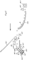
- Fig. 1
- zeigt in Draufsicht schematisch die Gesamtanordnung einer erfindungsgemäßen Vorrichtung mit drei Einlegevorrichtungen;
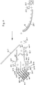
- Fig. 2
- zeigt schematisch in Draufsicht und vergrößert die Zuführung der Gegenstände zu einer Einlegevorrichtung, wobei im Interesse der klaren Darstellung Teile weggelassen sind;
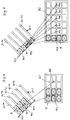
- Fig. 3
- ist eine Darstellung ähnlich der Fig. 2, wobei jedoch die Gegenstände nicht auf zwei sondern auf vier Reihen verteilt werden;
- Fig. 4 und Fig. 5
- veranschaulichen die Flexibilität des Zuführsystems bei einer Zuführung der Gegenstände in vier Reihen zu einer Einlegevorrichtung und beim Einlegen der dadurch gebildeten Gegenstandsgruppen in Behälter.
- Fig. 1
- shows a schematic top view of the overall arrangement of a device according to the invention with three insertion devices;
- Fig. 2
- shows schematically in plan view and enlarged the feed of the objects to an insertion device, parts being omitted in the interest of clarity;
- Fig. 3
- is a representation similar to Figure 2, however, the objects are not divided into two but four rows.
- 4 and 5
- illustrate the flexibility of the delivery system when feeding the articles in four rows to an insertion device and when inserting the groups of articles formed thereby into containers.
Wie insbesondere Fig. 1 zeigt, kommen die zu verarbeitenden Gegenstände oder Artikel A von einer Herstellungsmaschine auf einem Zuführförderer 1 in mehr oder weniger geordneten und ausgerichteten Querreihen R an. Die Gegenstände A werden an einen Beschleunigungsförderer 3 übergeben, durch den die Reihen R in Förderrichtung auseinandergezogen werden. Hiernach gelangen die Reihen R der Gegenstände A auf einen Hauptförderer 5, auf dem sie unter Beschleunigung weiter in Förderrichtung auseinandergezogen werden und auf dem sie mittels dreier Verteil- und Einlegeeinrichtungen I, II und III verarbeitet werden, wie unten im einzelnen beschrieben wird. Anschließend werden die Gegenstände in leere Behälter Bl eingelegt, die auf einer Förderbahn 11.1 ankommen und auf eine weitere, parallel neben dem Hauptförderer 5 verlaufende Förderbahn 11.2 übergeben werden. Neben der Förderbahn 11.2 verläuft parallel eine Füllstrecke 13, auf die die leeren Behälter Bl übergeben werden und auf der sie mit Gegenständen A gefüllt werden, so daß auf der Füllstrecke 13 leere Behälter Bl und gefüllte Behälter Bf laufen. Von der Füllstrecke 13 werden die gefüllten Behälter Bf auf einen Sammelförderer 15 für gefüllte Behälter Bf übergeben. Die Förderbahnen 11.2, 13 und 15 laufen parallel zueinander neben dem Hauptförderer 5 her. Die Übergabe der Behälter B von der einen zur anderen Förderbahn geschieht mittels bekannter Einrichtungen, z.B. Querschiebeeinrichtungen.As shown in FIG. 1 in particular, the objects or articles A to be processed arrive from a production machine on a
Im folgenden wird anhand der Fig. 1 die Verteil- und Einlegeeinrichtung I beschrieben.The distribution and insertion device I is described below with reference to FIG. 1.
Über dem Hauptförderer 5 ist eine Sammelschiene 21.1 angeordnet, an der die Gegenstände oder Artikel A zur Anlage kommen und zu einer Bahn hintereinanderliegender Gegenstände zusammengeführt werden. Die Gegenstände werden im weiteren Verlauf der Verteil-und Einlegeeinrichtung I zugeführt. Die Verteil- und Einlegeeinrichtung I arbeitet unabhängig von den weiteren Verteil- und Einlegeeinrichtungen II und III, so daß unterschiedliche Teilmengen, die den einzelnen Verteil- und Einlegeeinrichtungen zeitweise zugeführt werden, zu keinerlei Störungen des Betriebsablaufes führen.A busbar 21.1 is arranged above the
Am Ende der Sammelschiene 21.1 kann vorzugsweise eine Vorrichtung zur optischen oder visuellen Erkennung 23.1 der Gegenstände angeordnet sein. Hierdurch ist eine Qualitätskontrolle für die ankommenden Gegenstände gegeben. Mittels der Erkennungsvorrichtung 23.1 wird eine in Förderrichtung folgende Aussteuervorrichtung oder Ausschleusvorrichtung 25.1 gesteuert, die beispielsweise eine Blasdüse aufweist, durch die fehlerhafte oder beschädigte Gegenstände seitlich aus der Förderbahn ausgeschleust werden, wie durch Pfeile angedeutet, und zwar auf einen dafür seitlich vorgesehenen Bereich des Hauptförderers 5. Diese ausgesonderten Gegenstände laufen bis zum Ende des Hauptförderers 5 weiter und können dort eingesammelt werden.At the end of the busbar 21.1, a device for optical or visual recognition 23.1 of the objects can preferably be arranged. This provides a quality control for the incoming items. By means of the detection device 23.1, a control device or discharge device 25.1 following in the conveying direction is controlled, which, for example, has a blowing nozzle through which defective or damaged objects are discharged from the side of the conveying path, as indicated by arrows, to an area of the
Im Anschluß an die bisher beschriebenen Vorrichtungsteile ist eine vorzugsweise gekrümmte oder gebogene Zuführschiene 27.1 vorgesehen, längs welcher die Gegenstände A dicht hintereinander aufgereiht werden. Eine gekrümmte Zuführschiene 27.1 ist besser als eine gerade verlaufende Zuführschiene dafür geeignet, die Artikel A zu den nachfolgend angeordneten Teilaggregaten zu übergeben. Durch entsprechende Ausbildung des Krümmungsradius am Ende der Zuführschiene 27.1 kann auch bei ungleichmäßiger Beschickung ein gleichbleibender Mindestabstand zwischen den abgegebenen Gegenständen A erreicht oder aufrechterhalten werden.Following the previously described device parts, a preferably curved or curved feed rail 27.1 is provided, along which the objects A are lined up closely one behind the other. A curved feed rail 27.1 is better suited than a straight feed rail for moving the articles A to those arranged below Sub-units to be handed over. By appropriately designing the radius of curvature at the end of the feed rail 27.1, even with uneven loading, a constant minimum distance between the objects A delivered can be achieved or maintained.
Sofern die von der Zuführschiene 27.1 abgegebenen Gegenstände A nicht von der nachfolgenden Einrichtung aufgenommen werden oder werden können, können diese Gegenstände A durch eine in Förderrichtung hinter der Zuführschiene 27.1 angeordnete Umsteuerungseinrichtung 29.1, die beispielsweise wiederum durch eine Blasdüse gebildet ist, seitlich quer zur Förderrichtung zu einer Ableitschiene 31.1 umgelenkt werden, die die abgeleiteten Gegenstände der nächsten Verteil- und Einlegeeinrichtung II zuführt. Um zu vermeiden, daß dieser Einrichtung dadurch eine zu große oder etwa verdoppelte Gegenstandsmenge zugeführt wird, ist an der Vorrichtung II ebenfalls eine Umsteuereinrichtung 30.2 vorgesehen, beispielsweise wiederum eine Blasdüse, die den ursprünglich für die Einrichtung II vorgesehenen Gegenstandsstrom ganz oder teilweise zu der nachfolgenden Einrichtung III umleitet. Die Ansteuerung der Umsteuereinrichtungen 29.1 und/oder 30.2 bzw. der entsprechenden Blasdüsen erfolgt über eine Wegstreckenmessung, d.h. ein vom Hauptförderer 5 angetriebener Impulsgeber kontrolliert genau die Position der einzelnen Gegenstände A und schafft somit die Voraussetzung für eine entsprechende Ansteuerung der Umsteuereinrichtungen 29.1 und 30.2.If the objects A discharged from the feed rail 27.1 cannot or cannot be picked up by the subsequent device, these objects A can be moved laterally transversely to the conveying direction by means of a reversing device 29.1 arranged in the conveying direction behind the feed rail 27.1, which in turn is formed, for example, by a blowing nozzle a deflection rail 31.1 are deflected, which feeds the derived objects to the next distribution and insertion device II. In order to prevent this device from being supplied with an excessively large or roughly doubled amount of objects, a reversing device 30.2 is also provided on the device II, for example again a blowing nozzle, which wholly or partly leads the article flow originally intended for the device II to the subsequent device III redirects. The control of the reversing devices 29.1 and / or 30.2 or the corresponding blowing nozzles takes place via a distance measurement, i.e. a pulse generator driven by the
Der Einsatz von Blasdüsen ist für eine Umsteuerung der Gegenstände A vorzuziehen. Hierdurch wird eine schnelle, produktschonende, formunabhängige und preiswerte Einrichtung verwendet.The use of blow nozzles is preferable for reversing objects A. As a result, a quick, product-friendly, shape-independent and inexpensive facility is used.
Die bisher beschriebenen Teile der Verteil- und Einlegeeinrichtung I sind in Fig. 2 vergrößert dargestellt, ebenso wie die nachfolgend zu beschreibenden Teile der Vorrichtung. Nach der Zuführschiene 27.1 gelangen die Gegenstände A bei ordnungsgemäßem Betrieb in den Einlegebereich eines Sammelschachtes 33.1. Dieser ist kammartig mit Trennwänden 33.1a, 33.1b und 33.1c ausgebildet. Hierdurch kann eine zweireihige Gegenstandsformation gebildet werden. Bei Anordnung mehrerer Trennwände können entsprechend mehrreihige Gegenstandsformationen in dem Sammelschacht 33.1 gebildet werden, siehe Fig. 3. Diese Gegenstandsformationen entsprechen dem Packungsinhalt oder Packungsbild der zu füllenden Behälter Bf bzw. bei größeren Behältern jeweils einem Teil des Behälterinhalts.The parts of the distribution and insertion device I described so far are shown enlarged in FIG. 2, as are the parts of the device to be described below. After the feed rail 27.1, the objects A arrive in the insertion area of a collecting shaft 33.1 when properly operated. This is comb-like with partitions 33.1a, 33.1b and 33.1c. In this way, a two-row object formation can be formed. If several dividing walls are arranged, corresponding multi-row object formations can be formed in the collecting shaft 33.1, see FIG. 3. These object formations correspond to the package contents or package image of the containers Bf to be filled or, in the case of larger containers, to part of the container contents.
Innerhalb des kammförmigen Sammelschachts 33.1 werden die Gegenstände A auf Stau gefahren. Durch schräge Anordnung des Sammelschachtes 33.1 gegenüber der Förderrichtung des Hauptförderers 5 wird der Staudruck auf die jeweils ersten Gegenstände A vor einem Anschlag 41.1 reduziert, so daß damit eine Beschädigungsgefahr vermindert wird. Der Anschlag 41.1 bildet praktisch eine Null-Linie für das Aufreihen der Gegenstände. Eine zwiete Null-Linie bilden die seitlichen Trennwände 33.1a, 33.1b und 33.1c, gegen die die Gegenstände aufgrund der schrägen Anordnung anliegen. Somit ergeben sich zwei Null-Linien, die ein genaues Ausrichten der Gegenstände auch bei Größenabweichungen erlauben. Weiterhin erlaubt diese Anordnung die Verarbeitung auch von unterschiedlichen Artikelformen innerhalb bestimmter Grenzen ohne Veränderung des Sammelschachtes.The objects A are driven in a traffic jam within the comb-shaped collecting shaft 33.1. By arranging the collecting shaft 33.1 obliquely with respect to the conveying direction of the
Der Anschlag 41.1 ist an einer Schwenkachse 43.1 drehbar gelagert. Somit können für den Fall, daß die Gegenstände A nicht aus dem Sammelschacht 33.1 ordnungsgemäß entnommen werden können, diese Gegenstände durch Verschwenken des Anschlages 41.1 aus dem Sammelschacht 33.1 freigegeben und, wie die durch die Aussteuereinrichtung 25.1 ausgeschleusten Gegenstände, auf den seitlichen Bereich des Hauptförderers 5 geführt und an dessen Ende eingesammelt werden.The stop 41.1 is rotatably mounted on a pivot axis 43.1. Thus, in the event that the objects A cannot be removed properly from the collecting shaft 33.1, these objects can be released from the collecting shaft 33.1 by pivoting the stop 41.1 and, like the objects discharged by the actuating device 25.1, onto the lateral area of the
Am Einlauf des Sammelschachtes 33.1 ist in Förderrichtung hinter der Umsteuereinrichtung 29.1 eine Zähleinrichtung 35.1, z.B. in Form einer Lichtschranke, vorgesehen, die eine Verteileinrichtung 37.1, beispielsweise wiederum in Form einer Blasdüse, derart steuert, daß die Gegenstände A in ihrer Stückzahl genau auf die einzelnen Reihen des Sammelschachts 33.1 verteilt werden, wodurch wiederum unnötiger Staudruck in den einzelnen Reihen vermieden oder reduziert wird.At the inlet of the collecting shaft 33.1 in the conveying direction behind the reversing device 29.1 there is a counting device 35.1, e.g. in the form of a light barrier, which controls a distribution device 37.1, for example again in the form of a blowing nozzle, in such a way that the number of items A are distributed precisely over the individual rows of the collecting shaft 33.1, which in turn avoids unnecessary dynamic pressure in the individual rows or is reduced.
Zwischen der Umsteuereinrichtung 29.1 und der Zähleinrichtung 35.1 ist vorteilhafterweise eine kurze Führung 36.1 für die Gegenstände A angeordnet, um diese genau in Förderrichtung dem Sammelschacht 33.1 zuzuführen.A short guide 36.1 for the objects A is advantageously arranged between the reversing device 29.1 and the counting device 35.1 in order to feed them to the collecting shaft 33.1 exactly in the conveying direction.
Am Sammelschacht 33.1 ist eine weitere Zähleinrichtung 39.1, z.B. eine Lichtschranke, angeordnet, die feststellt, wenn der Sammelschacht 33.1 gefüllt ist. Die Lichtschranke veranlaßt einerseits die Freigabe für das Aufnehmen der Gegenstände durch den zugehörigen Einleger E1, und andererseits wird dadurch die Umsteuereinrichtung 29.1 zum Ableiten weiterer Gegenstände A zu der Ableitschiene 31.1 gesteuert. Dies erfolgt z.B. dann, wenn durch eine Störung die Gegenstände nicht aus dem Sammelschacht 33.1 entnommen wurden.A further counting device 39.1, for example a light barrier, is arranged on the collecting shaft 33.1, which detects when the collecting shaft 33.1 is filled. The light barrier on the one hand triggers the release for picking up the objects by the associated insert E1, and on the other hand controls the reversing device 29.1 to divert further objects A to the diverter rail 31.1. This occurs, for example, if the objects have not been removed from the collecting shaft 33.1 due to a malfunction.
Der Anschlag 41.1 am Ende des Sammelschachtes 33.1 kann beispielsweise durch pneumatische oder elektronische Mittel automatisch, ggfs. aber auch von Hand verschwenkt werden, um ein Ablaufen der Gegenstände A aus dem Sammelschacht 33.1 im Falle einer Störung zu ermöglichen.The stop 41.1 at the end of the collecting shaft 33.1 can be pivoted automatically, for example, by pneumatic or electronic means, if necessary, but also by hand, in order to allow objects A to run out of the collecting shaft 33.1 in the event of a fault.
Wie Fig. 1 zeigt, ist dem Sammelschacht 33.1 ein Einleger I zugeordnet, mit dem die Gegenstände A aus dem Sammelschacht 33.1 in einen Behälter B überführt werden. Der Einleger I weist einen seitlich neben den Behälterförderern 11.2, 13 und 15 schwenkbar gelagerten Schwenkarm 61 auf, an dem schwenkbar ein Einlegearm 63 gelagert ist, der an seinem freien Ende eine Gegenstandsaufnahme 65 trägt. Diese wird über den Sammelschacht 33.1 geschwenkt und nimmt aus diesem die dort angesammelten Gegenstände A nach oben heraus, beispielsweise mittels mechanischer oder pneumatischer Greifer. Durch Verschwenken des Schwenkarms 61 und des Einlegearms 63 werden die aus dem Sammelschacht 33.1 entnommenen Gegenstände A über einen leeren Behälter Bl geführt und in diesen eingelegt, indem die Gegenstände von der Gegenstandsaufnahme 65 freigegeben werden. Dabei behalten die Gegenstände in dem gefüllten Behälter Bf die gleiche gegenseitige Zuordnung wie in dem Sammelschacht 33.1. Grundsätzlich können je nach Anwendungsfall alle bekannten Arten von Einlegern, wie mechanisch angetriebene oder servoangetriebene Zweiachs-Aggregate oder aber auch Roboter zum Einsatz kommen.As shown in FIG. 1, an insert I is assigned to the collecting shaft 33.1, with which the objects A are transferred from the collecting shaft 33.1 into a container B. The insert I has a
Um das Einlegen der Gegenstände in die Behälter B zu ermöglichen, sind dem Einleger I an der Füllstrecke 13 geeignete Anschlag- und Zentriereinrichtungen für die zu füllenden, leeren Behälter Bl zugeordnet. Diese Einrichtungen sind in der Zeichnung nicht dargestellt. Die Länge der Füllstrecke 13 bildet gleichzeitig einen Zwischenpuffer für leere Behälter Bl, wie es für die Zuteilung der leeren Behälter Bl von der Förderbahn 11.2 zu der Füllstrecke 13 zweckmäßig oder erforderlich ist. Die Übergabe der gefüllten Behälter Bf von der Füllstrecke 13 auf den Sammelförderer 15 erfolgt wiederum durch Querverschiebung in bekannter Weise. Durch geeignete Anschlag- und Steuereinrichtungen wird jeweils im richtigen Zeitpunkt auf dem Sammelförderer 15 ein Bereich für die Übergabe eines gefüllten Behälters Bf freigehalten.In order to enable the objects to be inserted into the containers B, the insert I on the filling
Die zweite Verteil- und Einlegeeinrichtung II ist im Prinzip in gleicher Weise aufgebaut wie die erste Verteil- und Einlegeeinrichtung I. Die zweite Einrichtung II weist somit zunächst eine Sammelschiene 22.2 und die bereits erwähnte Umsteuereinrichtung 30.2 auf, von der überzählige Gegenstände zu einer Ableitschiene 32.2 abgeleitet werden. Die in der Einrichtung II verbleibenden Gegenstände gelangen längs einer Führung 34.2, zusammen mit ggfs. von der Ableitschiene 31.1 kommenden Gegenständen, zu einer Sammelschiene 21.2, die der Sammelschiene 21.1 der ersten Einrichtung I entspricht. Von hier an ist die Einrichtung II in gleicher Weise ausgebildet wie die Einrichtung I. Sie weist also eine Einrichtung 23.2 zur visuellen oder optischen Erkennung der Gegenstände sowie eine Aussteuereinrichtung 25.2 auf, an die sich eine, vorzugsweise wiederum gekrümmte Zuführschiene 27.2 anschließt. Dieser folgt eine Umsteuereinrichtung 29.2, um für Störfälle Gegenstände A zu einer zweiten Ableitschiene 31.2 ableiten zu können. Für den eigentlichen Gegenstandsstrom folgt dann in der Einrichtung II wieder ein Sammelschacht 33.2, vor dem eine Zähleinrichtung 35.2 und eine Verteileinrichtung 37.2 angeordnet sind. Der Sammelschacht 33.2 ist in gleicher Weise aufgebaut wie der Sammelschacht 33.1. Auch der Einleger II ist in gleicher Weise aufgebaut und arbeitet in gleicher Weise wie der Einleger I.In principle, the second distribution and insertion device II is constructed in the same way as the first distribution and insertion device I. The second device II thus initially has a busbar 22.2 and the reversing device 30.2 already mentioned, from which excess objects are derived to a discharge rail 32.2 become. The objects remaining in the device II pass along a guide 34.2, together with if necessary. objects coming from the busbar 31.1 to a busbar 21.2 which corresponds to the busbar 21.1 of the first device I. From here on, the device II is designed in the same way as the device I. It thus has a device 23.2 for the visual or optical recognition of the objects and a control device 25.2, which is followed by a, preferably again curved, feed rail 27.2. This is followed by a reversing device 29.2 in order to be able to discharge objects A to a second diverter rail 31.2 in the event of faults. For the actual article flow, a collection shaft 33.2 then follows in the device II, in front of which a counting device 35.2 and a distribution device 37.2 are arranged. The collecting shaft 33.2 is constructed in the same way as the collecting shaft 33.1. The insert II is constructed in the same way and works in the same way as the insert I.
Fig. 1 zeigt schließlich eine dritte Verteil- und Einlegeeinrichtung III, die analog zu den beiden vorhergehenden Einrichtungen I und II ausgebildet ist. Die Einrichtung III weist daher an ihrem einlaufseitigen Anfang eine Sammelschiene 22.3, eine Umsteuereinrichtung 30.3 für eine Ableitschiene 32.3 sowie eine Führung 34.3 auf. An diese schließt sich die eigentliche Sammelschiene 21.3 an, gefolgt von einer optischen Erkennungseinrichtung 23.3 und einer Aussteuereinrichtung 25.3 sowie von einer, vorzugsweise wiederum gekrümmten Zuführschiene 27.3. Mittels einer Umsteuereinrichtung 29.3 können überzählige Gegenstände zu einer Ableitschiene 31.3 gefördert und am Ende des Hauptförderers 5 eingesammelt werden. Der Hauptgegenstandsstrom gelangt jedoch zu einem Sammelschacht 33.3, dem wieder eine Zähleinrichtung 35.3 und eine Verteileinrichtung 37.3 vorgeordnet sind. Schließlich ist ein Einleger III vorhanden, der in gleicher Weise ausgebildet ist und arbeitet wie die beiden vorhergehenden Einleger I und II.1 finally shows a third distribution and insertion device III, which is designed analogously to the two preceding devices I and II. The device III therefore has a busbar 22.3, a reversing device 30.3 for a diverter rail 32.3 and a guide 34.3 at its inlet end. This is followed by the actual busbar 21.3, followed by an optical detection device 23.3 and a control device 25.3 and by a feed rail 27.3, which is preferably again curved. By means of a reversing device 29.3, surplus objects can be conveyed to a discharge rail 31.3 and collected at the end of the
Die zuvor beschriebene Vorrichtung und deren Verfahrensweise bieten im Vergleich zu bekannten mechanischen Einlegevorrichtungen oder Vorrichtungen mit Robotern im wesentlichen folgende Vorteile:
- 1. Die Vorrichtung ist flexibel hinsichtlich der Bildung von unterschiedlichen Gegenstandsgruppen.
- 2. Die Vorrichtung ist flexibel hinsichtlich der Verarbeitung von unterschiedlichen, jedoch untereinander gleichen Gegenständen.
- 3. Durch die Bereitstellung abgezählter Gegenstands- oder Produktgruppen ist eine hohe Einlegeleistung erreichbar. Dadurch kann die Anzahl der vorzusehenden Einleger I bis III erheblich reduziert werden. Der Einsparungsfaktor kann in der Größenordnung von 2
oder 3, je nach Einsatzfall, liegen. Die Mehrkosten für das hier beschriebene Zuführsystem stehen in keinem Verhältnis zu den Kosten, die durch eine hohe Zahl von Einlegern verursacht werden. - 4. Durch die reduzierte Zahl von Einlegern kann der gesamte Platzbedarf für die komplette Einlegevorrichtung größenordnungsmäßig ebenfalls um einen Faktor 2
bis 3, bezogen auf die Länge der Anlage, reduziert werden. - 5. Im Gegensatz zu Robotern mit visuellen Erkennungseinrichtungen, bei denen mindestens vier gesteuerte Achsen erforderlich sind, genügen für die Einleger I bis III nach der Erfindung Aggregate, die in zwei Achsrichtungen arbeiten können (mechanisch angetriebene, pneumatisch angetriebene oder servomotorangetriebene Geräte).
- 6. Auch bei einem denkbaren Einsatz von Robotern, z.B. wenn Teilmengen einer Behälterfüllung eingelegt werden müssen, reduziert sich die erforderliche Anzahl der Roboter, da die Gegenstände dem Roboter bereitgestellt werden und somit der Roboter nur noch die Strecken zwischen dem Aufnahmepunkt und dem jeweiligen Abgabepunkt innerhalb des Behälters zurücklegen muß. Hingegen müssen beim Einsatz von Robotern mit visuellem Erkennungssystem zur Roboterführung und Mehrfachgreifvorrichtung alle Gegenstände zuerst einzeln aufgenommen werden, bevor sie gemeinsam eingelegt werden können.
- 1. The device is flexible with regard to the formation of different groups of objects.
- 2. The device is flexible with regard to the processing of different, but mutually identical objects.
- 3. A high insertion rate can be achieved by providing counted object or product groups. As a result, the number of inserts I to III to be provided can be considerably reduced. The saving factor can be of the order of 2 or 3, depending on the application. The additional costs for the feed system described here are disproportionate to the costs caused by a large number of inserts.
- 4. Due to the reduced number of inserts, the total space required for the complete insertion device can also be reduced by a factor of 2 to 3 in relation to the length of the system.
- 5. In contrast to robots with visual recognition devices, in which at least four controlled axes are required, aggregates which can work in two axis directions (mechanically driven, pneumatically driven or servomotor-driven devices) are sufficient for inserts I to III according to the invention.
- 6. Even with a conceivable use of robots, for example if partial quantities of a container filling have to be inserted, the required number of robots is reduced, since the objects are made available to the robot and thus the robot only the distances between the pick-up point and the respective delivery point within of the container. On the other hand, when using robots with a visual recognition system for robot guidance and multiple gripping devices, all objects must first be picked up individually before they can be inserted together.
Im normalen Betrieb der erfindungsgemäßen Vorrichtung arbeiten nur die Verteil- und Einlegeeinrichtungen I und II mit den Einlegern E I und E II. Die dritte Verteil- und Einlegeeinrichtung III mit dem Einleger E III arbeitet nur im Stand-by-Betrieb für überzählige Gegenstände A, die von den beiden vorhergehenden Einrichtungen I und II nicht verarbeitet werden können oder aus diesen abgeleitet werden.In normal operation of the device according to the invention, only the distributing and inserting devices I and II work with the inserts EI and E II. The third distributing and inserting device III with the insert E III only works in stand-by mode for excess items A which cannot be processed by or derived from the two preceding devices I and II.
Fig. 3 zeigt eine Vorrichtung, bei der der Sammelschacht 33.1 nicht zwei Reihen, sondern vier Reihen von Gegenständen A aufnimmt. Gleiche Teile sind mit den gleichen Bezugsziffern bezeichnet wie in Fig. 1 und Fig. 2. Hier sind jedoch für die vier Gegenstandsreihen insgesamt fünf Trennwände 33.1a, 33.1b, 33.1c, 33.1d und 33.1e vorgesehen. Außerdem ist zusätzlich zu der Zähleinrichtung 35.1 und der Verteileinrichtung 37.1 jeweils eine zweite Zähleinrichtung 55.1 und eine zweite Verteileinrichtung 57.1 auf der gegenüberliegenden Seite am Einlauf des Sammelschachtes 33.1 vorgesehen. Jede dieser Einrichtungen steuert somit die Gegenstände für zwei der vier Bahnen des Sammelschachtes 33.1. Vor dieser Anordnung sind im Einlaufbereich des Sammelschachtes 33.1 eine weitere Zähleinrichtung 45.1, eine Verteileinrichtung 47.1 und eine V-förmige Führung 49.1 vorgesehen. Mit diesen Bauteilen werden die ankommenden Gegenstände A zunächst auf zwei Bahnen längs der Führungen 38.1 und 40.1 aufgeteilt. Im übrigen entspricht die Vorrichtung nach Fig. 3 der vorstehend in bezug auf Fig. 2 beschriebenen Einrichtung. Die Gegenstände können aus den vier Bahnen des Sammelschachtes 33.1 von Fig. 3 mittels eines Einlegers E I in gleicher Weise entnommen und in Behälter eingelegt werden, wie vorstehend bereits beschrieben.FIG. 3 shows a device in which the collecting shaft 33.1 accommodates not four rows but four rows of objects A. The same parts are designated with the same reference numerals as in FIGS. 1 and 2. Here, however, a total of five partition walls 33.1a, 33.1b, 33.1c, 33.1d and 33.1e are provided for the four rows of items. In addition to the counting device 35.1 and the distribution device 37.1, there is also a second one Counting device 55.1 and a second distribution device 57.1 are provided on the opposite side at the inlet of the collecting shaft 33.1. Each of these devices thus controls the objects for two of the four tracks of the collecting shaft 33.1. Before this arrangement, a further counting device 45.1, a distribution device 47.1 and a V-shaped guide 49.1 are provided in the inlet area of the collecting shaft 33.1. With these components, the incoming objects A are first divided into two tracks along the guides 38.1 and 40.1. Otherwise, the device according to FIG. 3 corresponds to the device described above with reference to FIG. 2. The objects can be removed from the four tracks of the collecting shaft 33.1 of FIG. 3 in the same way by means of an insert EI and placed in containers, as already described above.
Schließlich veranschaulichen die Fig. 4 und 5 die Flexibilität des Zuführsystems. Als Beispiel wurde eine vierbahnige Gegenstandszuführung nach Fig. 3 gewählt. Durch unterschiedliche Programmierung und Steuerung der Verteil- und Einlegeeinrichtung können dem Sammelschacht 33.1 und damit dem Einleger E I jeweils Teilmengen eines zu füllenden Behälters Bf zugeführt und für das Einlegen bereitgestellt werden. Die Punkte M 1 bis M 10 bezeichnen jeweils die Mittelpunkte des über dem Sammelschacht 33.1 bzw. über einem Behälter B 1 oder B 2 stehenden Greifers des Einlegers E I.Finally, Figures 4 and 5 illustrate the flexibility of the delivery system. A four-lane article feed according to FIG. 3 was chosen as an example. Through different programming and control of the distribution and insertion device, partial quantities of a container Bf to be filled can be supplied to the collecting shaft 33.1 and thus the insert E I and made available for insertion. The
Hiermit können ohne Umstellarbeiten an der Vorrichtung selbst, lediglich durch Änderung der Programmierung und der Steuerung, unterschiedliche Packformationen erzeugt werden. Als einziges Wechselteil sind hierbei die Greifelemente oder Greifer 65 am Einleger E I auszutauschen.With this, different pack formations can be generated without any changeover work on the device itself, simply by changing the programming and the control. The only interchangeable part here is to replace the gripping elements or
- AA
- Gegenstände, ArtikelObjects, articles
- BB
- Behältercontainer
- BfBf
- gefüllter Behälterfilled container
- BlBl
- leerer Behälterempty container
- RR
- Querreihen von GegenständenLateral rows of objects
- II.
- 1. Verteil- und Einlegeeinrichtung1. Distribution and insertion device
- IIII
- 2. Verteil- und Einlegeeinrichtung2. Distribution and insertion device
- IIIIII
- 3. Verteil- und Einlegeeinrichtung3. Distribution and insertion device
- E IE I
- Einleger IDepositor I
- E IIE II
- Einleger IIDepositor II
- E IIIE III
- Einleger IIIDepositor III
- MM
- MittelpunkteCenters
- 11
- ZuführfördererFeed conveyor
- 33rd
- BesehleunigungsförderAccelerator
- 55
- HauptfördererMain sponsor
- 11.111.1
-
Förderbahn für leere Behälter, 1. TeilConveyor path for empty containers,
part 1 - 11.211.2
- Förderbahn für leere Behälter, 2. TeilConveyor path for empty containers, part 2
- 1313
- Füllstrecke für BehälterFilling line for containers
- 1515
- Sammelförderer für gefüllte BehälterCollective conveyor for filled containers
- 21.121.1
- Sammelschiene IBusbar I
- 21.221.2
- Sammelschiene IIBusbar II
- 21.321.3
- Sammelschiene IIIBusbar III
- 22.222.2
- Sammelschiene IIBusbar II
- 22.322.3
- Sammelschiene IIIBusbar III
- 23.123.1
- optisch-visuelle Erkennung Ioptical-visual recognition I
- 23.223.2
- optisch-visuelle Erkennung IIoptical-visual recognition II
- 23.323.3
- optisch-visuelle Erkennung IIIoptical-visual recognition III
- 25.125.1
- Aussteuerung ILevel I
- 25.225.2
- Aussteuerung IILevel II
- 25.325.3
- Aussteuerung IIILevel III
- 27.127.1
- Zuführschiene IFeed rail I
- 27.227.2
- Zuführschiene IIFeed rail II
- 27.327.3
- Zuführschiene IIIFeed rail III
- 29.129.1
- Umsteuerung IReversal I
- 29.229.2
- Umsteuerung IIReversal II
- 29.329.3
- Umsteuerung IIIReversal III
- 30.230.2
- Umsteuerung IIReversal II
- 30.330.3
- Umsteuerung IIIReversal III
- 31.131.1
- Ableitschiene IDischarge bar I
- 31.231.2
- Ableitschiene IIDischarge rail II
- 31.331.3
- Ableitschiene IIIDischarge rail III
- 32.232.2
- Ableitschiene IIDischarge rail II
- 32.332.3
- Ableitschiene IIIDischarge rail III
- 33.133.1
- Sammelschacht ICollecting shaft I
- 33.233.2
- Sammelschacht IICollecting shaft II
- 33.333.3
- Sammelschacht IIICollecting shaft III
- 33.1a33.1a
- Trennwandpartition wall
- 33.1b33.1b
- Trennwandpartition wall
- 33.1c33.1c
- Trennwandpartition wall
- 33.1d33.1d
- Trennwandpartition wall
- 33.1e33.1e
- Trennwandpartition wall
- 34.234.2
- Führung IILeadership II
- 34.334.3
- Führung IIILeadership III
- 35.135.1
- Zähleinrichtung ICounter I
- 35.235.2
- Zähleinrichtung IICounter II
- 35.335.3
- Zähleinrichtung IIICounter III
- 36.136.1
- Führung ILeadership I
- 37.137.1
- Verteileinrichtung IDistribution device I
- 37.237.2
- Verteileinrichtung IIDistribution device II
- 37.337.3
- Verteileinrichtung IIIDistribution device III
- 38.138.1
- Führungguide
- 39.139.1
- LichtschrankePhotoelectric barrier
- 40.140.1
- Führungguide
- 41.141.1
- Anschlag, schwenkbarStop, swiveling
- 43.143.1
- SchwenkachseSwivel axis
- 45.145.1
- ZähleinrichtungCounting device
- 47.147.1
- VerteileinrichtungDistribution device
- 49.149.1
- Führungguide
- 55.155.1
- ZähleinrichtungCounting device
- 57.157.1
- VerteileinrichtungDistribution device
- 6161
- SchwenkarmSwivel arm
- 6363
- EinlegearmInlay arm
- 6565
- Gegenstands-Aufnahme, GreiferObject pick-up, gripper
Claims (17)
gekennzeichnet durch folgende Schritte:
characterized by the following steps:
gekennzeichnet durch folgende Merkmale:
characterized by the following features:
Applications Claiming Priority (2)
| Application Number | Priority Date | Filing Date | Title |
|---|---|---|---|
| DE4415561A DE4415561A1 (en) | 1994-05-03 | 1994-05-03 | Delivery and distribution system for objects |
| DE4415561 | 1994-05-03 |
Publications (2)
| Publication Number | Publication Date |
|---|---|
| EP0680883A1 true EP0680883A1 (en) | 1995-11-08 |
| EP0680883B1 EP0680883B1 (en) | 1998-12-16 |
Family
ID=6517165
Family Applications (1)
| Application Number | Title | Priority Date | Filing Date |
|---|---|---|---|
| EP95105464A Expired - Lifetime EP0680883B1 (en) | 1994-05-03 | 1995-04-11 | System for feeding and distributing articles |
Country Status (3)
| Country | Link |
|---|---|
| US (1) | US5603199A (en) |
| EP (1) | EP0680883B1 (en) |
| DE (2) | DE4415561A1 (en) |
Families Citing this family (13)
| Publication number | Priority date | Publication date | Assignee | Title |
|---|---|---|---|---|
| US7080962B1 (en) | 2005-05-31 | 2006-07-25 | Kimberly-Clark Worldwide, Inc. | Air conveyance apparatus |
| CN103540518B (en) | 2010-07-23 | 2015-07-08 | 贝克曼考尔特公司 | Test box |
| DE102010041346A1 (en) * | 2010-09-24 | 2012-03-29 | Loesch Verpackungstechnik Gmbh | Method and device for filling a multi-row packaging tray with lumpy products |
| JP6014123B2 (en) | 2011-05-13 | 2016-10-25 | ベックマン コールター, インコーポレイテッド | Laboratory product transport elements and pathway arrays |
| ES2689169T3 (en) | 2011-05-13 | 2018-11-08 | Beckman Coulter, Inc. | System and method that includes laboratory product transport element |
| EP2586712B2 (en) * | 2011-10-31 | 2018-02-14 | Veltru AG | Method and device for inserting products into containers in a robot street |
| US8973736B2 (en) | 2011-11-07 | 2015-03-10 | Beckman Coulter, Inc. | Magnetic damping for specimen transport system |
| BR112014011046A2 (en) | 2011-11-07 | 2017-06-13 | Beckman Coulter, Inc. | workflow and centrifuge system |
| WO2013070740A1 (en) | 2011-11-07 | 2013-05-16 | Beckman Coulter, Inc. | Aliquotter system and workflow |
| WO2013070754A1 (en) | 2011-11-07 | 2013-05-16 | Beckman Coulter, Inc. | Robotic arm |
| KR20140091033A (en) | 2011-11-07 | 2014-07-18 | 베크만 컬터, 인코포레이티드 | Specimen container detection |
| CN104053997B (en) | 2011-11-07 | 2016-12-21 | 贝克曼考尔特公司 | For processing the system and method for sample |
| WO2014043474A1 (en) | 2012-09-14 | 2014-03-20 | Beckman Coulter, Inc. | Analytical system with capillary transport |
Citations (4)
| Publication number | Priority date | Publication date | Assignee | Title |
|---|---|---|---|---|
| GB1274788A (en) * | 1970-03-04 | 1972-05-17 | Theegarten Franz | Packing installation for chocolates, chocolate-coated sweets and the like |
| DE3130103A1 (en) * | 1981-04-01 | 1982-10-21 | Menge Spezialmaschinen GmbH, 3530 Warburg | Process and apparatus for the automatic preparation of the packaging of easily breakable products, for example chocolate-covered cream cakes |
| EP0082123A2 (en) * | 1981-12-11 | 1983-06-22 | Bo Sammens | Procedure and arrangement for automatically aligning and inserting in packages products from belt conveyors |
| DE3243500A1 (en) * | 1982-11-24 | 1984-05-24 | Ferrero Ohg, 3570 Stadtallendorf | METHOD AND DEVICE FOR PACKING SPACIAL OBJECTS |
Family Cites Families (24)
| Publication number | Priority date | Publication date | Assignee | Title |
|---|---|---|---|---|
| DE7232986U (en) * | 1972-12-14 | Hodefleiss & Co Maschinen- U Apparatebau | Provisioning device for packing bottles, cans or similar vessels | |
| DE1251208B (en) * | 1967-09-28 | Schoko-Buck GmbH, Stuttgart | Method and apparatus for aligning irregularly shaped objects | |
| AT217374B (en) * | 1960-02-08 | 1961-09-25 | Sig Schweiz Industrieges | Device on a conveyor belt connecting a storage hopper with a counting device for bodies for aligning the bodies in a row |
| CH396749A (en) * | 1962-10-11 | 1965-07-31 | Sig Schweiz Industrieges | Device for counting and separating flat objects standing upright |
| DE1267592B (en) * | 1964-12-04 | 1968-05-02 | Enzinger Union Werke Ag | Multi-lane bottle storage table for bottle wrapping machines |
| US3370720A (en) * | 1966-02-11 | 1968-02-27 | Rheingold Breweries Inc | Keg handling system |
| US3429416A (en) * | 1967-07-18 | 1969-02-25 | Package Machinery Co | Transfer conveyor apparatus for candy bars and the like |
| DE1801165A1 (en) * | 1968-10-04 | 1970-05-21 | Josef Weigl | Reversible head boat |
| DE1924123B2 (en) * | 1969-05-12 | 1972-04-06 | Otto Hansel GmbH, 3000 Hannover | DEVICE FOR CUTTING UP SUEDE PARTS |
| US3693778A (en) * | 1970-12-30 | 1972-09-26 | Kaman Aerospace Corp | Assembly for use with conveyor system for separating and diverting objects |
| US3841205A (en) * | 1973-04-11 | 1974-10-15 | Scripps E Co | Electromechanical detector system and method for controlling flow of newspaper bundles |
| CH608451A5 (en) * | 1976-12-13 | 1979-01-15 | Sig Schweiz Industrieges | Apparatus for counting off articles and for filling them into containers |
| US4214663A (en) * | 1977-07-11 | 1980-07-29 | Oscar Lucks Company | Transfer apparatus for selectively transferring objects from a delivery conveyor to selected sections of a receiving conveyor |
| DE2801387A1 (en) * | 1978-01-13 | 1979-07-19 | Bernhard Heuft | SORTING MACHINE |
| CH625474A5 (en) * | 1978-02-14 | 1981-09-30 | Sig Schweiz Industrieges | |
| US4462516A (en) * | 1982-01-05 | 1984-07-31 | G.A.R.Bo. S.N.C. Di Guerzoni Alessandro E Renato | Container orienting and directing apparatus |
| DE3235632A1 (en) * | 1982-09-25 | 1984-03-29 | Gregor 7954 Bad Wurzach Holzmann | Method and device for the treatment of tightly packed workpieces on a transport device, in particular for age-hardening of glass workpieces |
| CH655698A5 (en) * | 1984-03-15 | 1986-05-15 | Sapal Plieuses Automatiques | INSTALLATION FOR FILLING WITH DIFFERENT KINDS OF PRODUCTS, PREFORMED TRAYS FOR ASSORTMENT BOXES. |
| US4736570A (en) * | 1984-12-03 | 1988-04-12 | Food Machinery Sales, Inc. | Automatic cookie loading system with double discharge |
| US4628665A (en) * | 1985-03-01 | 1986-12-16 | Mobil Oil Corporation | Modular indexing table for a box loading system |
| CH680509A5 (en) * | 1986-11-21 | 1992-09-15 | Ferag Ag | |
| DE3736610A1 (en) * | 1987-10-29 | 1989-05-11 | Hoefliger Harro Verpackung | Apparatus for transporting bags in groups of any size |
| US5078255A (en) * | 1991-01-14 | 1992-01-07 | Food Machinery Sales, Inc. | Cookie conveying system with diverter |
| DE9204040U1 (en) * | 1992-03-26 | 1992-05-14 | Krones Ag Hermann Kronseder Maschinenfabrik, 8402 Neutraubling, De |
-
1994
- 1994-05-03 DE DE4415561A patent/DE4415561A1/en not_active Withdrawn
-
1995
- 1995-04-11 DE DE59504531T patent/DE59504531D1/en not_active Expired - Fee Related
- 1995-04-11 EP EP95105464A patent/EP0680883B1/en not_active Expired - Lifetime
- 1995-05-01 US US08/431,762 patent/US5603199A/en not_active Expired - Fee Related
Patent Citations (4)
| Publication number | Priority date | Publication date | Assignee | Title |
|---|---|---|---|---|
| GB1274788A (en) * | 1970-03-04 | 1972-05-17 | Theegarten Franz | Packing installation for chocolates, chocolate-coated sweets and the like |
| DE3130103A1 (en) * | 1981-04-01 | 1982-10-21 | Menge Spezialmaschinen GmbH, 3530 Warburg | Process and apparatus for the automatic preparation of the packaging of easily breakable products, for example chocolate-covered cream cakes |
| EP0082123A2 (en) * | 1981-12-11 | 1983-06-22 | Bo Sammens | Procedure and arrangement for automatically aligning and inserting in packages products from belt conveyors |
| DE3243500A1 (en) * | 1982-11-24 | 1984-05-24 | Ferrero Ohg, 3570 Stadtallendorf | METHOD AND DEVICE FOR PACKING SPACIAL OBJECTS |
Also Published As
| Publication number | Publication date |
|---|---|
| DE4415561A1 (en) | 1995-11-09 |
| EP0680883B1 (en) | 1998-12-16 |
| DE59504531D1 (en) | 1999-01-28 |
| US5603199A (en) | 1997-02-18 |
Similar Documents
| Publication | Publication Date | Title |
|---|---|---|
| EP2616341B1 (en) | Method and device for filling a multi-row packaging tray with fragmented products | |
| DE102011009181A1 (en) | Device and method for transporting articles | |
| EP0638478B1 (en) | Device for removing receptacles from containers | |
| EP0680883B1 (en) | System for feeding and distributing articles | |
| DE102007021146A1 (en) | Apparatus and method for handling flat objects, in particular diapers | |
| AT405640B (en) | PICKING SYSTEM | |
| EP2586712B2 (en) | Method and device for inserting products into containers in a robot street | |
| WO2020094289A2 (en) | Device for grouping containers | |
| EP3423361B1 (en) | Section of a packaging line for beverage containers and method for handling beverage containers during their transport along a packaging line | |
| EP3303153B1 (en) | Air conditioning device, in particular for a vehicle | |
| DE202019005396U1 (en) | Packaging system and device for feeding products from a first process to a second process in a packaging system | |
| EP0987179B1 (en) | Method and apparatus for transferring packages at a piling station | |
| EP0411411A1 (en) | Method for transferring continuously moving transverse lines of objects on an endless conveyor, particularly confectionery products such as chocolate bars, pralines and apparatus therefor | |
| EP0644119A1 (en) | Method and device for the forming of stacks of individual articles, especially biscuits | |
| EP4188848A1 (en) | Transport device and method for distributing a plurality of similarly shaped and dimensioned articles | |
| DE2926792A1 (en) | RECEIVING STATION OF A PNEUMATIC CONVEYOR FOR THE TRANSPORT OF ROD-SHAPED ITEMS FROM THE TOBACCO-PROCESSING INDUSTRY, IN PARTICULAR OF FILTER RODS | |
| DE19930368A1 (en) | Method and device for packaging flat products | |
| DE3924274A1 (en) | TRANSPORTATION DEVICE FOR FEEDING AND TRANSPORTING FULL AND EMPTY PACKAGE CARRIERS TO AND AT LEAST ONE SPINNING MACHINE | |
| DE102022106309B3 (en) | Method and device for feeding products from a first process to a second process and for forming product stacks in a packaging line | |
| DE19506031C1 (en) | Method for continuous storing and bringing back items on conveyor system | |
| DE102022003027B3 (en) | Device for the synchronized transfer of objects | |
| WO2002098738A1 (en) | Device for removing bags from pile carriers and for separating the same | |
| DE3409225A1 (en) | Device for transfer of articles, especially ampoules | |
| DE19620599C2 (en) | Method for supplying shipping and freight goods to a sorting or distribution system and device for carrying out the method | |
| EP4029811A1 (en) | Conveyor belt for transporting goods and packaging line of a packaging system with such a conveyor belt |
Legal Events
| Date | Code | Title | Description |
|---|---|---|---|
| PUAI | Public reference made under article 153(3) epc to a published international application that has entered the european phase |
Free format text: ORIGINAL CODE: 0009012 |
|
| AK | Designated contracting states |
Kind code of ref document: A1 Designated state(s): CH DE ES FR IT LI NL |
|
| 17P | Request for examination filed |
Effective date: 19960410 |
|
| 17Q | First examination report despatched |
Effective date: 19970319 |
|
| GRAG | Despatch of communication of intention to grant |
Free format text: ORIGINAL CODE: EPIDOS AGRA |
|
| GRAG | Despatch of communication of intention to grant |
Free format text: ORIGINAL CODE: EPIDOS AGRA |
|
| GRAH | Despatch of communication of intention to grant a patent |
Free format text: ORIGINAL CODE: EPIDOS IGRA |
|
| GRAH | Despatch of communication of intention to grant a patent |
Free format text: ORIGINAL CODE: EPIDOS IGRA |
|
| GRAA | (expected) grant |
Free format text: ORIGINAL CODE: 0009210 |
|
| AK | Designated contracting states |
Kind code of ref document: B1 Designated state(s): CH DE ES FR IT LI NL |
|
| PG25 | Lapsed in a contracting state [announced via postgrant information from national office to epo] |
Ref country code: NL Free format text: LAPSE BECAUSE OF FAILURE TO SUBMIT A TRANSLATION OF THE DESCRIPTION OR TO PAY THE FEE WITHIN THE PRESCRIBED TIME-LIMIT Effective date: 19981216 Ref country code: IT Free format text: LAPSE BECAUSE OF FAILURE TO SUBMIT A TRANSLATION OF THE DESCRIPTION OR TO PAY THE FEE WITHIN THE PRE;WARNING: LAPSES OF ITALIAN PATENTS WITH EFFECTIVE DATE BEFORE 2007 MAY HAVE OCCURRED AT ANY TIME BEFORE 2007. THE CORRECT EFFECTIVE DATE MAY BE DIFFERENT FROM THE ONE RECORDED.SCRIBED TIME-LIMIT Effective date: 19981216 Ref country code: FR Free format text: LAPSE BECAUSE OF FAILURE TO SUBMIT A TRANSLATION OF THE DESCRIPTION OR TO PAY THE FEE WITHIN THE PRESCRIBED TIME-LIMIT Effective date: 19981216 Ref country code: ES Free format text: THE PATENT HAS BEEN ANNULLED BY A DECISION OF A NATIONAL AUTHORITY Effective date: 19981216 |
|
| REG | Reference to a national code |
Ref country code: CH Ref legal event code: EP |
|
| RAP2 | Party data changed (patent owner data changed or rights of a patent transferred) |
Owner name: LOESCH VERPACKUNGSTECHNIK GMBH |
|
| REF | Corresponds to: |
Ref document number: 59504531 Country of ref document: DE Date of ref document: 19990128 |
|
| REG | Reference to a national code |
Ref country code: CH Ref legal event code: NV Representative=s name: PATENTANWAELTE SCHAAD, BALASS, MENZL & PARTNER AG |
|
| NLT2 | Nl: modifications (of names), taken from the european patent patent bulletin |
Owner name: LOESCH VERPACKUNGSTECHNIK GMBH |
|
| EN | Fr: translation not filed | ||
| NLV1 | Nl: lapsed or annulled due to failure to fulfill the requirements of art. 29p and 29m of the patents act | ||
| PLBE | No opposition filed within time limit |
Free format text: ORIGINAL CODE: 0009261 |
|
| STAA | Information on the status of an ep patent application or granted ep patent |
Free format text: STATUS: NO OPPOSITION FILED WITHIN TIME LIMIT |
|
| 26N | No opposition filed | ||
| PGFP | Annual fee paid to national office [announced via postgrant information from national office to epo] |
Ref country code: CH Payment date: 20010423 Year of fee payment: 7 |
|
| PGFP | Annual fee paid to national office [announced via postgrant information from national office to epo] |
Ref country code: DE Payment date: 20010601 Year of fee payment: 7 |
|
| PG25 | Lapsed in a contracting state [announced via postgrant information from national office to epo] |
Ref country code: LI Free format text: LAPSE BECAUSE OF NON-PAYMENT OF DUE FEES Effective date: 20020430 Ref country code: CH Free format text: LAPSE BECAUSE OF NON-PAYMENT OF DUE FEES Effective date: 20020430 |
|
| PG25 | Lapsed in a contracting state [announced via postgrant information from national office to epo] |
Ref country code: DE Free format text: LAPSE BECAUSE OF NON-PAYMENT OF DUE FEES Effective date: 20021101 |
|
| REG | Reference to a national code |
Ref country code: CH Ref legal event code: PL |