EP0680818B1 - Fibre laying machine, presser assembly therefor, and method of laying and compacting fibre tows - Google Patents
Fibre laying machine, presser assembly therefor, and method of laying and compacting fibre tows Download PDFInfo
- Publication number
- EP0680818B1 EP0680818B1 EP19950105135 EP95105135A EP0680818B1 EP 0680818 B1 EP0680818 B1 EP 0680818B1 EP 19950105135 EP19950105135 EP 19950105135 EP 95105135 A EP95105135 A EP 95105135A EP 0680818 B1 EP0680818 B1 EP 0680818B1
- Authority
- EP
- European Patent Office
- Prior art keywords
- presser
- fibre
- laying
- assembly
- tows
- Prior art date
- Legal status (The legal status is an assumption and is not a legal conclusion. Google has not performed a legal analysis and makes no representation as to the accuracy of the status listed.)
- Expired - Lifetime
Links
- 239000000835 fiber Substances 0.000 title claims description 104
- 238000000034 method Methods 0.000 title claims description 9
- 230000033001 locomotion Effects 0.000 claims description 39
- 239000002131 composite material Substances 0.000 claims description 7
- 239000013013 elastic material Substances 0.000 claims description 6
- 210000000707 wrist Anatomy 0.000 claims description 5
- 229920002635 polyurethane Polymers 0.000 claims description 3
- 239000004814 polyurethane Substances 0.000 claims description 3
- 239000002783 friction material Substances 0.000 claims description 2
- 230000035515 penetration Effects 0.000 claims 1
- 238000005056 compaction Methods 0.000 description 39
- 239000012530 fluid Substances 0.000 description 19
- 239000012528 membrane Substances 0.000 description 14
- 230000008859 change Effects 0.000 description 5
- 230000006872 improvement Effects 0.000 description 5
- 239000000463 material Substances 0.000 description 5
- 239000004033 plastic Substances 0.000 description 5
- 229920003023 plastic Polymers 0.000 description 5
- 230000004044 response Effects 0.000 description 5
- 238000005096 rolling process Methods 0.000 description 5
- 230000000712 assembly Effects 0.000 description 3
- 238000000429 assembly Methods 0.000 description 3
- 239000004809 Teflon Substances 0.000 description 2
- 229920006362 Teflon® Polymers 0.000 description 2
- 238000001816 cooling Methods 0.000 description 2
- 230000001815 facial effect Effects 0.000 description 2
- 230000007246 mechanism Effects 0.000 description 2
- 230000002265 prevention Effects 0.000 description 2
- 229910000831 Steel Inorganic materials 0.000 description 1
- 239000000853 adhesive Substances 0.000 description 1
- 230000001070 adhesive effect Effects 0.000 description 1
- 229910052782 aluminium Inorganic materials 0.000 description 1
- XAGFODPZIPBFFR-UHFFFAOYSA-N aluminium Chemical compound [Al] XAGFODPZIPBFFR-UHFFFAOYSA-N 0.000 description 1
- 239000011230 binding agent Substances 0.000 description 1
- 238000004891 communication Methods 0.000 description 1
- 238000010276 construction Methods 0.000 description 1
- 230000007797 corrosion Effects 0.000 description 1
- 238000005260 corrosion Methods 0.000 description 1
- 238000005520 cutting process Methods 0.000 description 1
- 230000007423 decrease Effects 0.000 description 1
- 230000007547 defect Effects 0.000 description 1
- 230000001419 dependent effect Effects 0.000 description 1
- 230000000694 effects Effects 0.000 description 1
- 229920001971 elastomer Polymers 0.000 description 1
- 239000013536 elastomeric material Substances 0.000 description 1
- 239000003822 epoxy resin Substances 0.000 description 1
- 238000009730 filament winding Methods 0.000 description 1
- 230000000977 initiatory effect Effects 0.000 description 1
- 238000004519 manufacturing process Methods 0.000 description 1
- 239000011159 matrix material Substances 0.000 description 1
- 229910052751 metal Inorganic materials 0.000 description 1
- 239000002184 metal Substances 0.000 description 1
- 150000002739 metals Chemical class 0.000 description 1
- 230000000704 physical effect Effects 0.000 description 1
- 229920000647 polyepoxide Polymers 0.000 description 1
- 229920000642 polymer Polymers 0.000 description 1
- 238000003825 pressing Methods 0.000 description 1
- 238000011084 recovery Methods 0.000 description 1
- 239000012858 resilient material Substances 0.000 description 1
- 229920005989 resin Polymers 0.000 description 1
- 239000011347 resin Substances 0.000 description 1
- 230000000284 resting effect Effects 0.000 description 1
- 230000000717 retained effect Effects 0.000 description 1
- 239000010959 steel Substances 0.000 description 1
Images


Classifications
-
- B—PERFORMING OPERATIONS; TRANSPORTING
- B29—WORKING OF PLASTICS; WORKING OF SUBSTANCES IN A PLASTIC STATE IN GENERAL
- B29C—SHAPING OR JOINING OF PLASTICS; SHAPING OF MATERIAL IN A PLASTIC STATE, NOT OTHERWISE PROVIDED FOR; AFTER-TREATMENT OF THE SHAPED PRODUCTS, e.g. REPAIRING
- B29C70/00—Shaping composites, i.e. plastics material comprising reinforcements, fillers or preformed parts, e.g. inserts
- B29C70/04—Shaping composites, i.e. plastics material comprising reinforcements, fillers or preformed parts, e.g. inserts comprising reinforcements only, e.g. self-reinforcing plastics
- B29C70/28—Shaping operations therefor
- B29C70/30—Shaping by lay-up, i.e. applying fibres, tape or broadsheet on a mould, former or core; Shaping by spray-up, i.e. spraying of fibres on a mould, former or core
- B29C70/32—Shaping by lay-up, i.e. applying fibres, tape or broadsheet on a mould, former or core; Shaping by spray-up, i.e. spraying of fibres on a mould, former or core on a rotating mould, former or core
-
- B—PERFORMING OPERATIONS; TRANSPORTING
- B29—WORKING OF PLASTICS; WORKING OF SUBSTANCES IN A PLASTIC STATE IN GENERAL
- B29C—SHAPING OR JOINING OF PLASTICS; SHAPING OF MATERIAL IN A PLASTIC STATE, NOT OTHERWISE PROVIDED FOR; AFTER-TREATMENT OF THE SHAPED PRODUCTS, e.g. REPAIRING
- B29C70/00—Shaping composites, i.e. plastics material comprising reinforcements, fillers or preformed parts, e.g. inserts
- B29C70/04—Shaping composites, i.e. plastics material comprising reinforcements, fillers or preformed parts, e.g. inserts comprising reinforcements only, e.g. self-reinforcing plastics
- B29C70/28—Shaping operations therefor
- B29C70/30—Shaping by lay-up, i.e. applying fibres, tape or broadsheet on a mould, former or core; Shaping by spray-up, i.e. spraying of fibres on a mould, former or core
- B29C70/38—Automated lay-up, e.g. using robots, laying filaments according to predetermined patterns
- B29C70/382—Automated fiber placement [AFP]
- B29C70/384—Fiber placement heads, e.g. component parts, details or accessories
-
- B—PERFORMING OPERATIONS; TRANSPORTING
- B29—WORKING OF PLASTICS; WORKING OF SUBSTANCES IN A PLASTIC STATE IN GENERAL
- B29C—SHAPING OR JOINING OF PLASTICS; SHAPING OF MATERIAL IN A PLASTIC STATE, NOT OTHERWISE PROVIDED FOR; AFTER-TREATMENT OF THE SHAPED PRODUCTS, e.g. REPAIRING
- B29C70/00—Shaping composites, i.e. plastics material comprising reinforcements, fillers or preformed parts, e.g. inserts
- B29C70/04—Shaping composites, i.e. plastics material comprising reinforcements, fillers or preformed parts, e.g. inserts comprising reinforcements only, e.g. self-reinforcing plastics
- B29C70/28—Shaping operations therefor
- B29C70/30—Shaping by lay-up, i.e. applying fibres, tape or broadsheet on a mould, former or core; Shaping by spray-up, i.e. spraying of fibres on a mould, former or core
- B29C70/38—Automated lay-up, e.g. using robots, laying filaments according to predetermined patterns
- B29C70/386—Automated tape laying [ATL]
- B29C70/388—Tape placement heads, e.g. component parts, details or accessories
-
- Y—GENERAL TAGGING OF NEW TECHNOLOGICAL DEVELOPMENTS; GENERAL TAGGING OF CROSS-SECTIONAL TECHNOLOGIES SPANNING OVER SEVERAL SECTIONS OF THE IPC; TECHNICAL SUBJECTS COVERED BY FORMER USPC CROSS-REFERENCE ART COLLECTIONS [XRACs] AND DIGESTS
- Y10—TECHNICAL SUBJECTS COVERED BY FORMER USPC
- Y10T—TECHNICAL SUBJECTS COVERED BY FORMER US CLASSIFICATION
- Y10T156/00—Adhesive bonding and miscellaneous chemical manufacture
- Y10T156/17—Surface bonding means and/or assemblymeans with work feeding or handling means
- Y10T156/1788—Work traversing type and/or means applying work to wall or static structure
- Y10T156/1795—Implement carried web supply
Definitions
- This invention relates to fibre laying machines. More particularly this invention relates to segmented presser assemblies employed in placing and compacting fibre tows onto a work surface or form and a method of laying and compacting fibre tows onto a workpiece.
- Fibre tow laying machines and fibre tape laying machines are well known in the art and enjoy increasing usage to produce composite plastic parts, especially in aerospace applications, to replace comparable metallic parts. These composite plastic parts advantageously have a high strength to weight ratio, are producible in complex shapes that eliminate the need for several individual metallic parts, exhibit corrosion resistance and have other desirable physical properties (e.g. low electrical and heat conductivity).
- Various fibre tow laying machines and improvements thereto have been described in the literature of the art and the distinctions and advantages of these machines over filament winding and tape laying machines has been well documented (see for example US Patent 4,699,683 to McCowin and US Patent 5,022,952 to Vaniglia).
- Fibre tow laying machines can individually feed and cut separate fibre bundles or tows forming a fibre band being laid down on a work surface or form. This selective cutting and feeding of tows advantageously allows the fibre placement head to put down the tows in an arcuate path on the work surface that prevents buckling, wrinkling or misalignment of fibres.
- the fibre tows also known as tow pregs, are generally a bundle of continuous fibres impregnated with a resin (i.e. a polymeric material that may be in a cured, uncured or partially cured state).
- the segmented presser assembly generally has a series of side-by-side parallel arranged individual linearly movable presser elements that engage fibre tows to lay and compact the tows onto a work surface or form.
- the presser elements which may be non-rotating or rotating elements, usually travel above and below a datum line. This improvement permits the presser assembly of the fibre tow laying and compacting head of a fibre tow laying machine to more easily and readily conform to changes in the contour of the work surface or form during the lay up procedure.
- segmented presser assemblies are described, for example, in US-A-4,292,108, US-A-4,601,775, US-A-4,867,834, US-A-4,869,774, US-A-5,015,326, US-A-5,045,147 and US-A-5,110,395.
- the prior art segmented presser assemblies commonly employ a resiliently deformable sleeve to cover and stretch across the fibre tow engaging faces of all the presser elements to form a continuous elastic or resilient fibre tow engaging surface for laying and compacting the fibre tows onto a work surface.
- This elastic sleeve is usually made of an elastomeric material such as elastomeric polyurethane.
- the elastic sleeve deforms in response to the changing contour. This deformation of the sleeve is mirrored by linear movement of individual presser elements contacting the sleeve so that the presser assembly maintains contact with the work surface during changes in the surface contour.
- the segmented presser assembly and elastic sleeve combination improves the lay down and compaction of fibre tows onto a work surface because of the improved conformation of the presser assembly to changes in the work surface contour and improved contact of the presser elements with the work surface.
- One of the problems is the added spring force that the common sleeve induces on the presser elements as they are forced to move against the sleeve especially during compaction of the tows. This force varies in a spring-rate-like manner and increases as the presser elements move further away from the mid-travel datum line as in the case when laying down and compacting over a convex surface. Since the common sleeve induces a sleeve resistance on the presser elements as they move it is difficult to maintain a uniform pressure gradient across the compaction line as the presser assembly lays and compacts the fibre tows over a varying contour.
- the common sleeve effectively decreases the compaction force output capability of the presser elements thus causing the compaction line force to be nonlinear with presser element position.
- the sleeve resistance is unsymmetrical about the centre line and increases with each presser element location moving away from the centre line in either direction.
- a second problem is caused by the stretching or bulging of the common sleeve. As the presser elements move to conform to the changing contour of the work surface they induce a shearing-like force into the sleeve. This shear-like force causes the sleeve to bulge out and not maintain a tight fit to the presser element.
- the sleeve distortion or bulging may affect the incoming fibre tow feed path and tend to produce degraded lap/gap within the tow band, tow wander at end cuts and degraded end cut accuracy that may, in turn, lead to imperfections or defects in the composite plastic article and thus to unreliable and scrap articles, as well as increased costs and lower production.
- a presser assembly in accordance with the preamble of claim 1 and a method of laying and compacting of a fibre tape are disclosed in US patent: US-A-4 915 771.
- Preferred embodiments are described in the dependent claims.
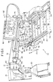
- a perspective view of a fibre tow laying machine 10 which mounts a fibre tow placement head 12, having a segmented presser assembly according to this invention, in a position to apply fibre tows 14 onto a mandrel 16 rotatably carried on a pair of mandrel supports 18, 20.
- the term "tow” is meant to refer to a composite strand consisting of a number of continuous fibres preferably impregnated with a binder or matrix material such as epoxy resin.
- the detailed construction and operation of the fibre tow laying machine 10 and mandrel supports 18 and 20 form no part of this invention. Reference should be made to US-A-5,022,952, assigned to the assignee of this application, for a detailed discussion of the fibre tow laying machine.
- the fibre tow laying machine 10 includes a base support 22 having substantially horizontally extending side rails 24, 26 which are interconnected by longitudinally spaced support beams 28.
- the side rails 24, 26 are connected at opposite ends to end panels 30, 32, each of which is supported by relatively short vertical legs 34.
- the base support 22 mounts a carriage 36 which comprises a pair of spaced beams 38, 40 interconnected by rods (not shown).
- Each of the beams 38, 40 has bearing blocks 50, 51 at opposite ends which slidably engage ways 52, 53 respectively mounted on the side rails 24, 26 of base support 22. Movement of the carriage 36 with respect to the base support 22 is effected by a rack and pinion drive.
- An elongated gear rack 54 is mounted to the underside of side rail 24 of base support 22 which is drivenly connected to a pinion (not shown) mounted to a gear box 55 and motor 56 connected by a support 57 to the carriage 36. Rotation of the pinion by operation of the motor 56 and gear box 55 causes the carriage 36 to move along the gear rack 54 parallel to the longitudinal axis of the base support 22, i.e. along the X axis as depicted in Figure 1.
- a cross slide 58 is pivotally mounted on opposite sides to a pair of bearings 60 each carried on a vertical column 66, one of which is shown in Figure 1.
- the vertical columns 66 in turn, are mounted on the beams 38, 40.
- a pair of ways 67 are mounted to cross slide 58, one of which is shown in Figure 1, which are carried by forward bushings 71 mounted to a tilt saddle having laterally spaced support plates 68, 70.
- the rearward end of each way 67 is carried by a bushing 73 connected to each bearing 60.
- the forward end of each support plate 68, 70 of the tilt saddle mounts an arcuate rack 72, one of which is shown in Figure 1.
- Each arcuate rack 72 is drivenly connected to a pinion (not shown) connected to the output of a gear box 74 driven by a motor 76.
- a first gear box 74 and motor 76 pair is mounted to a side wall 77 connected to a beam 40, and a second gear box and motor pair (not shown) is mounted to a side wall 78 connected to beam 38.
- the pinions drive arcuate racks 72 to pivot cross slide 58 on the bearings 60 in a substantially vertical direction, i.e. along a Y axis as depicted in Figure 1.
- a separate drive (not shown) is also provided to move the cross slide 58 along a Z axis wherein the ways 67 are movable along the bushings 71, 73. Additionally, motor 75 fixed to the rear of the cross slide 58 is drivenly connected by means (not shown) to rotate the fibre laying head 12 about the Z axis.
- One end of the cross slide 58 mounts a roll-bend-roll type robotics wrist 80 which carries the fibre laying head 12.
- the robotics wrist 80 is commercially available and is effective to move the fibre tow laying head 12 along a number of axes. Such motion provided by the robotics wrist 80 is in addition to the movement of cross slide 58 along the X axis with carriage 36, the pivotal and tilting movement of cross slide 58 along the Y axis and the cross feed movement of the cross slide 58 along the Z axis as described above.
- the fibre tow laying machine 10 is, therefore, capable of manipulating the position of the fibre tow laying head 12 along a number of axes with respect to the mandrel 16, and such motions are coordinated with the movement of the mandrel supports 18,20 by a controller (not shown) as discussed in detail in US-A-5,022,952.
- fibre tow laying machine 10 The operation of fibre tow laying machine 10 will now be further described with reference to Figures 1 and 2.
- the illustrated embodiment of the fibre tow laying machine 10 in Figure 1 is effective to supply a total of sixteen individual fibre tows 14 to a fibre tow laying head 12 for application onto the surface of mandrel 16.
- the fibre tows 14 are supplied from a creel assembly 82 carried on the cross slide 58 which includes eight individual spools 84 on one side and another eight spools (not shown) on the opposite side, each of which supplies a single fibre tow 14.
- tows 14 are drawn from spools 84 over a fixed roller 86 and a redirect roller 88, both mounted on the creel assembly 82, and a second redirect roller 90 mounted to the housing 13 of the fibre tow laying head 12.
- the purpose of the redirect rollers 88 and 90 is to maintain the same relative spatial orientation of the fibre tows 14 passing between the fibre laying head 12 and the creel assembly 82 as the fibre tow laying head 12 is manipulated with respect to the mandrel 16 and creel assembly 82.
- redirect rollers 88,90 forms no part of this invention per se.
- Eight fibre tows 14 are fed from the redirect roller 90 to an upper idler roller 92 ( Figure 2) rotatably mounted to the fibre tow laying head 12 and the other eight fibre tows 14 are directed from redirect roller 90 to a lower idler roller 94 mounted beneath the upper idler roller 92.
- the fixed roller 86, redirect rollers 88, 90 and the upper and lower idler rollers 92, 94 all include an individual roller for each tow 14; the individual rollers are mounted side-by-side and are rotatable relative to one another so that each tow 14 can be fed to the fibre tow laying head 12 at independent rates from the creel 82.
- Fibre tows 14 are guided from the upper and lower idler rollers 92, 94 through a cooling assembly, a cut, clamp and restart mechanism and a guide chute to beneath segmented presser assembly 100 and hence onto the surface of mandrel 16 under segmented presser assembly 100.
- the eight fibre tows from the upper roller 92 are parallel and laterally spaced from one another forming upper tows 14a and the eight fibre tows from lower idler roller 94 are parallel and laterally spaced from one another forming lower tows 14b.
- the upper and lower tows 14a and 14b are staggered or offset from one another so that upon exiting the guide chute the upper and lower tows 14a and 14b are laid down side by side onto the surface of the mandrel 16 forming an essentially continuous-width fibre band 101 which is pressed against the mandrel 16 by segmented presser assembly 100.
- the cooling assembly, cut, clamp and restart mechanism and guide chute forming part of fibre tow laying head 12 form not part of this invention and their structure and operation are discussed and described in detail in US-A-5,110,395.
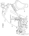
- FIG. 2 there is shown the fibre tow laying head 12 having a segmented presser assembly 100, for laying and compacting fibre tow 14 onto surface 104 of mandrel 16.
- the segmented presser assembly 100 is joined with a presser mount 102 and two side plates 105 (see Figure 3) by screws 106a, 106b, and carried by an attached slider 103 for moving segmented presser assembly 100 into and from engagement with surface 104 of mandrel 16.
- a compaction fluid cylinder 107 preferably a double-acting pneumatic cylinder, is mounted on bracket 108 attached to housing 13 and has a piston 109 passing through bracket 108 and joined to bracket assembly 110 mounted on slider 103 that moves slider 103 linearly on a linear slide table 103a to bring segmented presser assembly 100 into and out of compaction engagement with surface 104 of mandrel 16 for compacting fibre tow 14.
- Cylinder 107 provides controlled compaction force on the fibre tow and sets the level of compaction force on the fibre tow applied to mandrel 16.
- a null fluid cylinder 111 preferably a pneumatic cylinder, mounted on bracket 108 has a piston 112 that engages bracket assembly 110 to hold segmented presser assembly 100, carried on slider 103 in a null position and zero compaction force engagement with surface 104 at the initiation of a fibre tow laying and compaction operation.
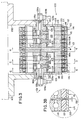
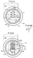
- FIG. 3 a partial section taken along line 3-3 of Figure 2.
- a plurality of presser element disks having a centre disk 113, a pair of end disks 114, 114a and several identical intermediate disks 115 located between the centre disk 113 and the end disks 114, 114a are mounted on a housing afforded by a support block 116 between side plates 105 in a side-by-side stacked parallel array.
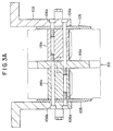
- Support block 116 is in two identical halves 116a, 116b joined together by screws 106a, 106b passing through the centre disk 113, each half 116a, 116b of support block 116, the side plates 105, and the presser mount 102 (see Figure 3a).
- the presser mount 102 is, in turn, carried on the slider 103 (see Figure 2).
- the centre disk 113 secured to support block 116 with two pins 117 (see Figure 4), remains stationary with respect to linear movement along a path coincident with the centre line W of the stacked array of disks.
- Intermediate disks 115 and end disks 114 are independently linearly movable on support block 116 in a path parallel to centre line W with changes in the contour of the surface of mandrel 16.
- Each of the disks has a low friction ball bearing 118 mounted on the periphery of the respective core 119, 119a, 119b, to provide rolling contact of the presser element disk with the surface 104 of mandrel 16 for laying and compacting fibre tows onto mandrel 16.
- the ball bearing 118 may be press-mounted onto the cores.
- the cores 119 of end disks 114 have a shoulder 120 that engages the ball bearing 118.
- a band 121 is attached to the outer periphery of ball bearing 118 on each presser element disk 113, 114, 115 that rotates with the bearing 118 and moves linearly with the linear movement of the presser element disk, independent of the rotary and linear movements of bands on adjacent presser element disks.
- each band 121 Attached to and covering the outer periphery of each band 121 is a low friction film ring 122 that forms the fibre tow engaging surface or face of each presser element disk 113, 114, 115 and which has the same rotary and linear movements as the band 121 to which it is attached independent of the rotary and linear movement the low-friction film rings 122 attached to adjacent bands 121 on adjacent presser element disks.
- the band 121 is of a material that deforms and regains its original shape and size upon removing the force that produces deformation of the band 121. Any suitable resilient material may be used for the band 121 including, but not limited to, elastomeric polymers; for example, elastomeric polyurethane.
- the low friction film ring 122 is of a material that exhibits low friction against the fibre tow.
- the low friction film ring 122 may be made of "Teflon" (Teflon is a registered trademark).
- segmented presser assembly 100 There is provided in the segmented presser assembly 100 (shown in Figure 3) two fluid pressure bladder springs 123a, 123b extending through the intermediate presser element disks 115 and the end presser element disks 114. These bladder springs 123a, 123b apply fluid pressure to the movable presser element disks (i.e. the intermediate presser element disks 115 and end presser element disks 114) during the compaction of the fibre tows onto the mandrel 16.
- Each of the bladder springs 123a, 123b has an elastic membrane 124 enclosing a chamber 125 and is confined by the centre presser element disk 113, the respective side plate 105, intermediate presser element disks 115, end presser element disks 114, and the support block 116.
- Clamping plates 126 retained by socket head cap screws 126a, clamp and seal the membranes 124 to the support block 116.
- Ports 127 through the cap screws 126a provide fluid communication between passageways 128a,b, and the respective chambers 125.
- Fluid passageways 128a,b in turn, connect to fluid supply inlets 129a,b.
- the fluid used to pressurize the bladder springs 123a, 123b is compressed air.
- the clamping plates 126 have a lip 130 for engaging and holding elastic membrane 124 in place against support block 116.
- pressurised fluid i.e. compressed air
- chamber 125 is pressurised, membrane 124 is forced against intermediate disks 115 and end disks 114 to move these disks toward the mandrel 16 and maintain contact of these presser element disks with the surface 104 of mandrel 16.
- the pressure of the compressed air is adjusted and maintained by a means (not shown) to provide constant contact of the presser element disks 114, 115 with surface 104 of mandrel 16.
- Centre disk 113, intermediate disks 115 and end disks 114 are spaced side-by-side so as to be close enough together to permit easy independent linear movement relative to each other.
- a gap 132 is provided between adjacent roller bearings 118, elastic bands 121 and low friction film rings 122, typically 0.005 inches (0.13mm) (see Figure 3b), sufficient to permit rotation and linear movement of the assembly of roller bearing 118, elastic band 121 and low friction ring 122 during the laying and compacting of fibre tows 14 onto mandrel 16.
- the centre presser element disk 113 (shown in Figure 4 in side elevation with partial section, taken along line 4-4 of Figure 3) is held stationary with respect to linear movement along a path coincident with centre line W ( Figure 3) and perpendicular to a datum axis 131 by screws 106a, 106b and a pair of pins 117 passing through core 119a of centre disk 113 into both halves 116a, 116b of support block 116.
- Ball bearing 118 having on its outer periphery elastic band 121 to which is attached low-friction film ring 122, provides rolling contact of centre presser element disk 113 with fibre tow 14 during the laying and compaction of the tow 14 onto mandrel 16.
- Figure 4a illustrates shallow facial reliefs, R, which are formed into the sides of the cores of the presser element disks to reduce the sliding area.
- Intermediate presser element disk 115 shown in Figure 5 in side elevation with partial section, taken along line 5-5 of Figure 3, is mounted on the support block 116, for linear movement along a path parallel to centre line W ( Figure 3) and perpendicular to a datum axis 131 ( Figure 3), through a substantially rectangular opening 133 formed by side guide surfaces 134a,b in core 119b of intermediate presser element disk 115.
- the bladder spring 123a passes through the lower end of opening 133 so as to place the elastic membrane 124 of bladder spring 123a in contact with core 119b of intermediate disk 115, whereby the bladder spring 123a, upon being pressurised, can exert a force on intermediate disk 115 in a direction toward mandrel 16 causing intermediate disk 115 to apply compaction pressure or force on fibre tow 14 on surface 104 of mandrel 16.
- Free space is provided at the upper end of opening 133 to permit the linear movement of intermediate disk 115 with changes in the contour of surface 104 during the laying and compaction of fibre tow 14.
- End presser element disk 114 shown in Figure 6 in side elevation with partial section, taken along line 6-6 of Figure 3, is mounted on the support block 116, for linear movement along a path parallel to centre line W ( Figure 3) and perpendicular to the datum axis 131 ( Figure 3), through a substantially rectangular opening 135 formed by side guide surfaces 136a,b in core 119 of end presser element disk 114.
- the bladder spring 123a passes through the lower end of opening 135 so as to place elastic membrane 124 of bladder spring 123a in contact with core 119 of end presser element disk 114 whereby bladder spring 123a, upon being pressurised, can exert a force on end disk 114 in a direction toward mandrel 16 thereby causing end presser element disk 114 to apply a compaction force on fibre tow 14 on surface 104 of mandrel 16.
- Free space is provided at the upper end of opening 135 to allow linear movement of end disk 114 in response to changes in the contour of surface 104 of mandrel 16.
- the ball bearing 118, on the outer periphery of core 119 and resting against flange 120 of core 119, and the band 121 and low friction film ring 122 carried thereby provide rolling contact between end presser element disk 114 and fibre tow 14 during the layup and compaction of tow 14.
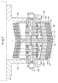
- a change in the configuration of segmented presser assembly 100 with respect to the position of the presser element disks in response to a change in the contour of surface 104 of mandrel 16 from a flat contour shown in Figure 3 to V-groove or valley contour is depicted in Figure 7.
- the centre presser element disk 113 is stationary with respect to linear movement along a path that is coincident with centre line W and perpendicular to datum axis 131 and thus any adjustment of the spatial position of centre disk 113 with a change in the contour of the surface 104 of mandrel 16 requires that the entire segmented presser assembly 100 move accordingly. Such movement was discussed earlier in conjunction with Figure 2 for the movement of segmented presser assembly 100.
- compaction force or pressure is applied by the centre presser element disk 113 to tow 14 on mandrel 16 by the fluid cylinder 107 moving the segmented presser assembly 100 into engagement with surface 104 of mandrel 16.
- the pressure of the fluid in chamber 125 of bladder springs 123a, 123b is adjusted to a value which would prevent disengaging centre disk 113 from contact with surface 104 and/or reduce the compaction force being applied by centre disk 113.
- fluid pressure in chamber 125 of bladder springs 123a and 123b would be kept at a value to provide compaction force being applied by the intermediate disks 115 and end disks 114 equal to the compaction force being applied by centre disk 113. This can be done by means for dumping pressurised fluid from or adding pressurised fluid to chamber 125. Such means for adjusting the pressure of the fluid in chamber 125 are well known in the art.
- each elastic band 121 and associated low friction film ring 122 on each linearly movable disk moves independently of adjacent elastic bands 121 and associated low friction film ring 122 on adjacent linearly movable disks.
- the elastic bands 121 and associated low friction film rings 122 are not connected together between adjacent disks. This is shown by the configuration of the upper end of the disks 113, 114, 115 of segmented presser assembly 100 shown in Figure 7.
- the independent movement of elastic bands 121 eliminates the spring or rubber band effect produced by a prior art continuous elastic sleeve or cover spanning adjacent linearly movable presser disks of a segmented presser assembly.
- FIG 8 An alternative embodiment of a segmented presser assembly in accordance with this invention is shown in Figure 8, in which there are fewer presser element disks than in the segmented presser assembly 100 of Figure 3.
- the low friction film rings 122 of Figure 3 are absent.
- the low friction film ring 122, that engages fibre tow 14 during laydown and compaction of the tow, is chosen so as to prevent sticking and/or high friction between the fibre tow engaging surface of the presser element disk and the fibre tow during the layup and compaction of the tow.
- Such prevention of sticking and/or high friction reduces or eliminates damage to the fibre tow, as well as poor tracking and misalignment of the tow on the surface of a mandrel or other work surface.
- Similar prevention of sticking and/or high friction between the fibre tow engaging face of a presser element (e.g. presser element disk) of a segmented presser assembly 138 can be achieved by having the elastic band 142 made of a material that has low friction and anti-sticking properties against the fibre tow.
- the segmented presser assembly 138 has a centre presser element disk 139, with intermediate and end presser element disks 140, 141 at each side.
- Each of the presser element disks 139,140,141 has, on the outer periphery, an elastic band 142 of a resilient low friction material that provides the fibre tow engaging face of the disk for laying and compacting the tow.
- the centre presser element disk 139 does not have linear radial movement capability with respect to its central datum axis 143, whereas the intermediate and end presser element disks 140,141 are free to move with independent linear motion perpendicular with respect to the central datum axis 143 with changes in the contour of the surface of a mandrel or other work surface during layup and compaction of the fibre tow.
- a ball bearing 144 is provided on the outer periphery of the core 145 of each of the movable presser element disks 140, 141, and the core 145a of the centre disk 139, to give rolling engagement of each disk with the fibre tows during layup and compaction of the tows.
- the segmented presser assembly 138 has a bladder spring 146, extending through all of the presser element disks 139, 140,141, having a flexible membrane 147 forming a chamber 148 and engaging each of the disks of the segmented presser assembly 138.
- the membrane 147 extends through a small, close-fitting opening 139a in the centre disk 139 in order to span all of the disks. Pressurised fluid (e.g.
- Block 151 has two halves 151a and 151b, held together by screws 156 and a pin 157 (see Figure 9), that capture the centre disk 139 and hold it stationary, with respect to linear movement normal the central datum axis 143.
- the halves 151a,b are piloted into the core 145a of the centre disk 139.
- the halves 151a are also fixed with the side plates 158 and mounting brackets 159a,b by pins 157.
- block 151 passes through an opening 160 which runs through the movable presser element disks 140, 141 to carry and guide the disks 140, 141 for independent linear movement normal to the central datum axis 143.
- Pressurised fluid e.g. compressed air
- entering chamber 148 pressurizes bladder spring 146 causing flexible membrane 147 to apply a force (i.e. compaction force) on the movable presser element disks 140, 141 that, in turn, apply the compaction force on fibre tows on the surface of a mandrel or other work surface (e.g. mold).
- the elastic bands 142 on adjacent presser element disks are separated from each other by a small gap that permits independent linear movement of the elastic bands 142, on adjacent disks, along with their associated presser element disks.
- this invention includes and may be practised with a segmented presser assembly wherein all presser elements are free to independently move linearly along a path parallel to or coincident with an imaginary line through the centre of the presser element and passing through the area of contact between the presser element and the work surface.
- the segmented presser assembly in accordance with this invention may comprise a plurality of presser elements wherein at least one of the presser elements is independently, linearly movable as previously described herein.
- the segmented presser assembly in accordance with this invention comprises a plurality of presser elements that are independently, linearly movable as previously described therein.
- the rotary motion of the presser elements in accordance with this invention may be achieved by various means well known in the art.
- One such means namely an antifriction ball bearing, has been identified herein.
- an antifriction bearing is employed to produce rotary movement to the presser element (e.g. presser element disk) the bearing may be attached by a press fit onto the presser element.
- Various other methods well known in the art, may be used to attach means for producing rotary motion to the presser element.
- the elastic band or elastic material layer may be adhesively attached to the presser element or may be attached to the presser element by other methods well known in the art which permit the deformation and recovery from deformation of the elastic band during layup and compaction of the fibre tows.
- the low-friction film may be attached to the elastic band with adhesive or other suitable means.
- Presser elements of the segmented presser assembly in accordance with this invention may be made of suitable rigid materials well known in the art, including but not limited to rigid plastic and metals such as steel and aluminum.
- the terms presser element and presser segment are interchangeably used herein and shall have the same meaning in respect to this description and the appended claims.
Landscapes
- Engineering & Computer Science (AREA)
- Chemical & Material Sciences (AREA)
- Composite Materials (AREA)
- Mechanical Engineering (AREA)
- Robotics (AREA)
- Moulding By Coating Moulds (AREA)
- Casting Or Compression Moulding Of Plastics Or The Like (AREA)
- Nonwoven Fabrics (AREA)
Applications Claiming Priority (2)
| Application Number | Priority Date | Filing Date | Title |
|---|---|---|---|
| US08/235,991 US5454897A (en) | 1994-05-02 | 1994-05-02 | Presser member for fiber laying machine |
| US235991 | 1994-05-02 |
Publications (3)
| Publication Number | Publication Date |
|---|---|
| EP0680818A2 EP0680818A2 (en) | 1995-11-08 |
| EP0680818A3 EP0680818A3 (fa) | 1995-11-29 |
| EP0680818B1 true EP0680818B1 (en) | 1997-08-06 |
Family
ID=22887686
Family Applications (1)
| Application Number | Title | Priority Date | Filing Date |
|---|---|---|---|
| EP19950105135 Expired - Lifetime EP0680818B1 (en) | 1994-05-02 | 1995-04-05 | Fibre laying machine, presser assembly therefor, and method of laying and compacting fibre tows |
Country Status (5)
| Country | Link |
|---|---|
| US (1) | US5454897A (fa) |
| EP (1) | EP0680818B1 (fa) |
| JP (1) | JP3018520U (fa) |
| DE (1) | DE69500513T2 (fa) |
| ES (1) | ES2105801T3 (fa) |
Families Citing this family (56)
| Publication number | Priority date | Publication date | Assignee | Title |
|---|---|---|---|---|
| EP0644040A1 (en) * | 1993-05-27 | 1995-03-22 | Cincinnati Milacron Inc. | Method of and apparatus for laying composite material |
| ES2112088B1 (es) * | 1993-11-30 | 1998-11-01 | Torres Martinez M | Cabezal de encintado para la aplicacion de cinta de fibra de carbono o similar. |
| JP3742111B2 (ja) * | 1996-10-25 | 2006-02-01 | ブイエムアイ エペ ホランド ベスローテン フェンノートシャップ | タイヤ形成装置用の圧力ロール |
| US5975179A (en) * | 1998-03-05 | 1999-11-02 | Kelly, Jr.; James E. | Tire stitching apparatus |
| US6112792A (en) * | 1998-11-19 | 2000-09-05 | The Boeing Company | Fiber placement mid-span redirect |
| US6390169B1 (en) | 2000-02-23 | 2002-05-21 | The Boeing Company | Conformable compaction apparatus for use with a fiber placement machine |
| US8256430B2 (en) | 2001-06-15 | 2012-09-04 | Monteris Medical, Inc. | Hyperthermia treatment and probe therefor |
| EP1799912A2 (en) * | 2004-10-12 | 2007-06-27 | 3M Innovative Properties Company | Film lamination vehicles and methods |
| US7472736B2 (en) * | 2005-02-14 | 2009-01-06 | The Boeing Company | Modular head lamination device and method |
| FR2882681B1 (fr) * | 2005-03-03 | 2009-11-20 | Coriolis Composites | Tete d'application de fibres et machine correspondante |
| US7353853B2 (en) * | 2005-05-03 | 2008-04-08 | Cincinnati Machine, Llc | Fiber placement machine |
| US7810539B2 (en) * | 2005-08-25 | 2010-10-12 | Ingersoll Machine Tools, Inc. | Compaction roller for a fiber placement machine |
| WO2007076775A1 (de) * | 2005-12-13 | 2007-07-12 | Institut Für Verbundwerkstoffe Gmbh | Andrückvorrichtung mit einer andrückrolle |
| US8042594B2 (en) * | 2006-06-28 | 2011-10-25 | Alliant Techsystems Inc. | Compaction device for fiber placement using interdependent segment travel |
| US7404868B2 (en) * | 2006-10-10 | 2008-07-29 | Accudyne Systems, Inc. | Tape placement head for applying thermoplastic tape to an object |
| US20080093026A1 (en) * | 2006-10-24 | 2008-04-24 | Niko Naumann | Device for pressing a tape |
| DE102006052592B4 (de) | 2006-11-08 | 2013-09-12 | Eads Deutschland Gmbh | Verfahren zur Ablage großer trockener Textilfaserbahnen |
| DE102008012255B4 (de) * | 2007-03-13 | 2017-03-16 | Airbus Defence and Space GmbH | Verfahren zum Herstellen eines textilen Halbzeugs mit kraftflussgerecht verlaufenden Faserfilamenten für eine kraftflussgerechte Faserverbundstruktur |
| DE102007012608B4 (de) * | 2007-03-13 | 2009-12-24 | Eads Deutschland Gmbh | Verfahren und Vorrichtung zum Herstellen einer Preform für eine kraftflussgerechte Faserverbundstruktur |
| DE102007012609B4 (de) | 2007-03-13 | 2010-05-12 | Eads Deutschland Gmbh | Legevorrichtung und Legestempel zur Verwendung in einer Legevorrichtung |
| DE102007063689B4 (de) * | 2007-03-13 | 2016-06-23 | Airbus Defence and Space GmbH | Elastischer Faserlegestempel |
| US7849903B2 (en) * | 2007-06-06 | 2010-12-14 | Cincinnati Machine, Llc | Motorized cut and feed head |
| US7717151B2 (en) * | 2007-11-29 | 2010-05-18 | Spirit Aerosystems, Inc. | Material placement method and apparatus |
| US7591294B2 (en) | 2007-11-29 | 2009-09-22 | Spirit Aerosystems, Inc. | Material placement method and apparatus |
| DE102008019147A1 (de) * | 2008-04-16 | 2009-10-22 | Airbus Deutschland Gmbh | Verfahren zur Herstellung von Faservorformlingen |
| US8728092B2 (en) | 2008-08-14 | 2014-05-20 | Monteris Medical Corporation | Stereotactic drive system |
| US8747418B2 (en) | 2008-08-15 | 2014-06-10 | Monteris Medical Corporation | Trajectory guide |
| DE102009014488A1 (de) * | 2009-03-23 | 2010-09-30 | Airbus Deutschland Gmbh | Andruckvorrichtung und Andruck- und Ablegesystem zum Ablegen von einem Faserband auf eine doppelt gekrümmte Fläche |
| DE102010013711A1 (de) * | 2010-04-02 | 2011-10-06 | Airbus Operations Gmbh | Andruckrolleneinheit zum Ablegen vorimprägnierter Faserbänder auf einer Oberfläche sowie Ablegeeinrichtung |
| US20120152432A1 (en) * | 2010-12-15 | 2012-06-21 | Samuel Francis Pedigo | Methods and systems for fiber placement using a stationary dispenser |
| FR2975334B1 (fr) * | 2011-05-20 | 2016-04-15 | Coriolis Composites Attn Olivier Bouroullec | Tete d'application de fibres avec rouleau de compactage segmente |
| US8903311B1 (en) | 2011-08-16 | 2014-12-02 | 5Me Ip, Llc | Method of signal transmission using fiber composite sandwich panel |
| US8684720B2 (en) | 2011-12-05 | 2014-04-01 | Fives Machining Systems, Inc. | Fiber delivery system for composite part manufacture |
| EP2866723A4 (en) | 2012-06-27 | 2016-12-14 | Monteris Medical Corp | IMAGE-guided THERAPY OF TISSUE |
| FR2999466B1 (fr) * | 2012-12-18 | 2015-06-19 | Airbus Operations Sas | Machine de placement de fibres comprenant un rouleau avec des bagues pivotantes |
| AT514550B1 (de) * | 2013-12-16 | 2015-02-15 | Gfm Gmbh | Vorrichtung zum Legen von Faserbändern |
| AT514551B1 (de) * | 2013-12-16 | 2015-02-15 | Gfm Gmbh | Vorrichtung zum Legen von Faserbändern |
| AT514797B1 (de) | 2013-12-16 | 2015-04-15 | Gfm Gmbh | Vorrichtung zum Legen von Faserbändern |
| DE102014102278B4 (de) * | 2014-02-21 | 2017-10-12 | Deutsches Zentrum für Luft- und Raumfahrt e.V. | Faserlegevorrichtung |
| US9486170B2 (en) | 2014-03-18 | 2016-11-08 | Monteris Medical Corporation | Image-guided therapy of a tissue |
| US10675113B2 (en) | 2014-03-18 | 2020-06-09 | Monteris Medical Corporation | Automated therapy of a three-dimensional tissue region |
| WO2015143026A1 (en) | 2014-03-18 | 2015-09-24 | Monteris Medical Corporation | Image-guided therapy of a tissue |
| DE102014105712B4 (de) * | 2014-04-23 | 2016-01-21 | Deutsches Zentrum für Luft- und Raumfahrt e.V. | Faserlegevorrichtung |
| US10040274B2 (en) * | 2014-06-17 | 2018-08-07 | The Boeing Company | Pre-filled radius layups |
| DE102014016404B4 (de) | 2014-11-05 | 2019-05-29 | Tekon D.O.O. | Bandverlegemaschine |
| US10327830B2 (en) | 2015-04-01 | 2019-06-25 | Monteris Medical Corporation | Cryotherapy, thermal therapy, temperature modulation therapy, and probe apparatus therefor |
| DE102015006372A1 (de) * | 2015-05-19 | 2016-11-24 | Harburg-Freudenberger Maschinenbau Gmbh | Andrückeinrichtung für Reifenaufbaumaschinen |
| FR3055111B1 (fr) * | 2016-08-16 | 2018-08-31 | Safran Aircraft Engines | Installation et procede de mise en forme d'une preforme fibreuse de revolution presentant en section radiale un profil evolutif |
| AT518786B1 (de) * | 2016-09-21 | 2018-01-15 | Fill Gmbh | Folienlegevorrichtung zum Herstellen eines Faserverbundwerkstoffes |
| US10960626B2 (en) * | 2017-06-05 | 2021-03-30 | Bridgestone Americas Tire Operations, Llc | Bidirectional tire stitching wheel |
| CN108688199B (zh) * | 2018-04-02 | 2019-12-13 | 中国科学院自动化研究所 | 可消除丝束粘附的气动压止装置 |
| US11273610B2 (en) | 2019-03-21 | 2022-03-15 | Goodrich Corporation | Manufacturing methods for composite driveshafts |
| US11813811B2 (en) * | 2019-05-22 | 2023-11-14 | The Boeing Company | Conformable apparatus, systems and methods for treating a composite material |
| FR3100154B1 (fr) * | 2019-09-04 | 2021-07-23 | Coriolis Group | Tete d'application de fibres avec rouleau a anneaux rigides |
| US11260605B2 (en) * | 2020-01-21 | 2022-03-01 | Goodrich Corporation | Flexible thermoplastic composite coupling and method of manufacture |
| CN113059829B (zh) * | 2021-03-09 | 2022-03-25 | 北京航空航天大学 | 一种热固性纤维预浸带隔离膜同步收集机构 |
Family Cites Families (23)
| Publication number | Priority date | Publication date | Assignee | Title |
|---|---|---|---|---|
| US2464020A (en) * | 1944-06-14 | 1949-03-08 | Gen Tire & Rubber Co | Tire building machine |
| US2838091A (en) * | 1955-08-17 | 1958-06-10 | Gen Tire & Rubber Co | Tire building machine |
| US4052246A (en) * | 1976-03-30 | 1977-10-04 | The Goodyear Tire & Rubber Company | Stitcher for tire building |
| DE2753272C2 (de) * | 1977-11-30 | 1985-08-29 | Metzeler Kautschuk GmbH, 8000 München | Anlegerolle |
| US4292108A (en) * | 1979-12-10 | 1981-09-29 | General Dynamics Corporation | Composite tape laying apparatus including means for plural longitudinal and transverse cuts |
| US4341584A (en) * | 1981-05-11 | 1982-07-27 | The Goodyear Tire & Rubber Company | Multiple disc stitcher |
| EP0250673B1 (en) * | 1986-07-04 | 1990-10-10 | Cincinnati Milacron Inc. | Composite tape laying machine with pivoting presser member |
| US4601775A (en) * | 1985-06-03 | 1986-07-22 | Cincinnati Milacron Inc. | Compliant presser member for composite tape laying machine |
| US5022952A (en) * | 1985-12-13 | 1991-06-11 | Cincinnati Milacron Inc. | Fiber placement machine |
| US4699683A (en) * | 1986-02-07 | 1987-10-13 | The Boeing Company | Multiroving fiber laminator |
| US4867834A (en) * | 1986-04-07 | 1989-09-19 | Hercules | Filament winding system |
| US4915771A (en) * | 1987-10-08 | 1990-04-10 | The Boeing Company | Segmented tape shoe |
| JPH0688340B2 (ja) * | 1988-03-28 | 1994-11-09 | 新日本工機株式会社 | テープの自動貼付装置 |
| US4869774A (en) * | 1988-09-26 | 1989-09-26 | Cincinnati Milacron Inc. | Compliant presser member for fiber placement machine |
| US5045147A (en) * | 1988-11-23 | 1991-09-03 | Hercules Incorporated | Filament winding system |
| US4954204A (en) * | 1988-11-25 | 1990-09-04 | Cincinnati Milacron Inc. | Presser member for contoured surfaces |
| US5015326A (en) * | 1989-05-08 | 1991-05-14 | The Boeing Company | Compliant tape dispensing and compacting head |
| US5110395A (en) * | 1989-12-04 | 1992-05-05 | Cincinnati Milacron Inc. | Fiber placement head |
| US5072359A (en) * | 1990-04-13 | 1991-12-10 | Cincinnati Milacron Inc. | Spatially-clocked digital steering servo for tape-laying machine |
| US5058497A (en) * | 1990-12-17 | 1991-10-22 | Mcdonnell Douglas Corporation | Compliant pressure roller |
| CA2057222C (en) * | 1990-12-19 | 1998-05-19 | Keith G. Shupe | Fiber placement delivery system |
| CA2057225C (en) * | 1990-12-19 | 1994-09-27 | John A. Johnson | Band fiber forming and placement delivery head |
| CA2057201C (en) * | 1990-12-19 | 1998-05-19 | Vernon M. Benson | Multiple axes fiber placement machine |
-
1994
- 1994-05-02 US US08/235,991 patent/US5454897A/en not_active Expired - Lifetime
-
1995
- 1995-02-09 JP JP1995000491U patent/JP3018520U/ja not_active Expired - Lifetime
- 1995-04-05 DE DE69500513T patent/DE69500513T2/de not_active Expired - Lifetime
- 1995-04-05 EP EP19950105135 patent/EP0680818B1/en not_active Expired - Lifetime
- 1995-04-05 ES ES95105135T patent/ES2105801T3/es not_active Expired - Lifetime
Also Published As
| Publication number | Publication date |
|---|---|
| DE69500513T2 (de) | 1997-12-04 |
| EP0680818A3 (fa) | 1995-11-29 |
| DE69500513D1 (de) | 1997-09-11 |
| JP3018520U (ja) | 1995-11-21 |
| ES2105801T3 (es) | 1997-10-16 |
| EP0680818A2 (en) | 1995-11-08 |
| US5454897A (en) | 1995-10-03 |
Similar Documents
| Publication | Publication Date | Title |
|---|---|---|
| EP0680818B1 (en) | Fibre laying machine, presser assembly therefor, and method of laying and compacting fibre tows | |
| US4943338A (en) | Multi-tow fiber placement machine with full band width clamp, cut, and restart capability | |
| EP0361828B1 (en) | Fiber placement machine, and fiber placement head | |
| US5110395A (en) | Fiber placement head | |
| US4627886A (en) | Composite tape laying machine with pivoting presser member | |
| KR101856113B1 (ko) | 섬유 스트립을 도포하기 위한 도포 헤드 | |
| EP1035963B1 (en) | Feed control system for fiber placement machines | |
| US4877193A (en) | Redirect roller apparatus for fiber placement machine | |
| US5015326A (en) | Compliant tape dispensing and compacting head | |
| CA2969657C (en) | Method and apparatus for laminating composites | |
| US4588466A (en) | Tape laying method and apparatus | |
| US6096164A (en) | Multiple axes fiber placement machine | |
| US4872619A (en) | Serco driven redirect roller apparatus for fiber placement machine | |
| EP0371289B1 (en) | Machine for applying composite material and presser assembly therefor | |
| EP0626251A1 (en) | Tape laying machine and method of laying plastic tape | |
| JPH01294165A (ja) | テープの自動貼付装置 | |
| US6422986B1 (en) | Sealer apparatus for forming a cross seal in plastic film processing and particularly for bag making machines | |
| EP0355308B1 (en) | Fibre placement machine | |
| EP0250673B1 (en) | Composite tape laying machine with pivoting presser member | |
| EP0797498B1 (en) | Open frame injection molding machine | |
| EP4427916B1 (en) | Fiber placement apparatus and method of molding composite material | |
| US5626707A (en) | Apparatus for manufacturing composite tubular articles | |
| KR20250117782A (ko) | 테이프 놓기 헤드 | |
| US12459216B2 (en) | Roller unit for feeding tapes, fiber placement apparatus and method of molding composite material | |
| EP4349573A1 (en) | Method of producing preform and method of molding composite material |
Legal Events
| Date | Code | Title | Description |
|---|---|---|---|
| PUAI | Public reference made under article 153(3) epc to a published international application that has entered the european phase |
Free format text: ORIGINAL CODE: 0009012 |
|
| PUAL | Search report despatched |
Free format text: ORIGINAL CODE: 0009013 |
|
| AK | Designated contracting states |
Kind code of ref document: A2 Designated state(s): BE DE ES FR GB IT |
|
| AK | Designated contracting states |
Kind code of ref document: A3 Designated state(s): BE DE ES FR GB IT |
|
| 17P | Request for examination filed |
Effective date: 19960111 |
|
| 17Q | First examination report despatched |
Effective date: 19960314 |
|
| GRAG | Despatch of communication of intention to grant |
Free format text: ORIGINAL CODE: EPIDOS AGRA |
|
| GRAH | Despatch of communication of intention to grant a patent |
Free format text: ORIGINAL CODE: EPIDOS IGRA |
|
| GRAH | Despatch of communication of intention to grant a patent |
Free format text: ORIGINAL CODE: EPIDOS IGRA |
|
| GRAA | (expected) grant |
Free format text: ORIGINAL CODE: 0009210 |
|
| AK | Designated contracting states |
Kind code of ref document: B1 Designated state(s): BE DE ES FR GB IT |
|
| ITF | It: translation for a ep patent filed | ||
| REF | Corresponds to: |
Ref document number: 69500513 Country of ref document: DE Date of ref document: 19970911 |
|
| REG | Reference to a national code |
Ref country code: ES Ref legal event code: FG2A Ref document number: 2105801 Country of ref document: ES Kind code of ref document: T3 |
|
| ET | Fr: translation filed | ||
| PLBE | No opposition filed within time limit |
Free format text: ORIGINAL CODE: 0009261 |
|
| STAA | Information on the status of an ep patent application or granted ep patent |
Free format text: STATUS: NO OPPOSITION FILED WITHIN TIME LIMIT |
|
| 26N | No opposition filed | ||
| REG | Reference to a national code |
Ref country code: GB Ref legal event code: IF02 |
|
| PGFP | Annual fee paid to national office [announced via postgrant information from national office to epo] |
Ref country code: BE Payment date: 20030617 Year of fee payment: 9 |
|
| PG25 | Lapsed in a contracting state [announced via postgrant information from national office to epo] |
Ref country code: BE Free format text: LAPSE BECAUSE OF NON-PAYMENT OF DUE FEES Effective date: 20040430 |
|
| BERE | Be: lapsed |
Owner name: CINCINNATI *MILACRON INC. Effective date: 20040430 |
|
| PGFP | Annual fee paid to national office [announced via postgrant information from national office to epo] |
Ref country code: GB Payment date: 20080429 Year of fee payment: 14 |
|
| REG | Reference to a national code |
Ref country code: GB Ref legal event code: 732E Free format text: REGISTERED BETWEEN 20090813 AND 20090819 |
|
| GBPC | Gb: european patent ceased through non-payment of renewal fee |
Effective date: 20090405 |
|
| REG | Reference to a national code |
Ref country code: FR Ref legal event code: TP |
|
| PG25 | Lapsed in a contracting state [announced via postgrant information from national office to epo] |
Ref country code: GB Free format text: LAPSE BECAUSE OF NON-PAYMENT OF DUE FEES Effective date: 20090405 |
|
| PGFP | Annual fee paid to national office [announced via postgrant information from national office to epo] |
Ref country code: ES Payment date: 20120426 Year of fee payment: 18 |
|
| PGFP | Annual fee paid to national office [announced via postgrant information from national office to epo] |
Ref country code: DE Payment date: 20130429 Year of fee payment: 19 |
|
| PGFP | Annual fee paid to national office [announced via postgrant information from national office to epo] |
Ref country code: IT Payment date: 20130422 Year of fee payment: 19 Ref country code: FR Payment date: 20130506 Year of fee payment: 19 |
|
| REG | Reference to a national code |
Ref country code: DE Ref legal event code: R119 Ref document number: 69500513 Country of ref document: DE |
|
| REG | Reference to a national code |
Ref country code: FR Ref legal event code: ST Effective date: 20141231 |
|
| REG | Reference to a national code |
Ref country code: DE Ref legal event code: R119 Ref document number: 69500513 Country of ref document: DE Effective date: 20141101 |
|
| PG25 | Lapsed in a contracting state [announced via postgrant information from national office to epo] |
Ref country code: DE Free format text: LAPSE BECAUSE OF NON-PAYMENT OF DUE FEES Effective date: 20141101 |
|
| PG25 | Lapsed in a contracting state [announced via postgrant information from national office to epo] |
Ref country code: FR Free format text: LAPSE BECAUSE OF NON-PAYMENT OF DUE FEES Effective date: 20140430 |
|
| PG25 | Lapsed in a contracting state [announced via postgrant information from national office to epo] |
Ref country code: IT Free format text: LAPSE BECAUSE OF NON-PAYMENT OF DUE FEES Effective date: 20140405 |
|
| REG | Reference to a national code |
Ref country code: ES Ref legal event code: FD2A Effective date: 20150526 |
|
| PG25 | Lapsed in a contracting state [announced via postgrant information from national office to epo] |
Ref country code: ES Free format text: LAPSE BECAUSE OF NON-PAYMENT OF DUE FEES Effective date: 20140406 |