EP0680593B2 - Plattenwärmetauscher - Google Patents
Plattenwärmetauscher Download PDFInfo
- Publication number
- EP0680593B2 EP0680593B2 EP94904278A EP94904278A EP0680593B2 EP 0680593 B2 EP0680593 B2 EP 0680593B2 EP 94904278 A EP94904278 A EP 94904278A EP 94904278 A EP94904278 A EP 94904278A EP 0680593 B2 EP0680593 B2 EP 0680593B2
- Authority
- EP
- European Patent Office
- Prior art keywords
- plates
- heat exchanger
- plate
- tie bar
- plate heat
- Prior art date
- Legal status (The legal status is an assumption and is not a legal conclusion. Google has not performed a legal analysis and makes no representation as to the accuracy of the status listed.)
- Expired - Lifetime
Links
- 230000006835 compression Effects 0.000 abstract description 4
- 238000007906 compression Methods 0.000 abstract description 4
- 210000003128 head Anatomy 0.000 description 7
- 239000012530 fluid Substances 0.000 description 2
- 239000002184 metal Substances 0.000 description 2
- 230000000295 complement effect Effects 0.000 description 1
- 238000012986 modification Methods 0.000 description 1
- 230000004048 modification Effects 0.000 description 1
- 230000000717 retained effect Effects 0.000 description 1
Images

Classifications
-
- F—MECHANICAL ENGINEERING; LIGHTING; HEATING; WEAPONS; BLASTING
- F28—HEAT EXCHANGE IN GENERAL
- F28F—DETAILS OF HEAT-EXCHANGE AND HEAT-TRANSFER APPARATUS, OF GENERAL APPLICATION
- F28F3/00—Plate-like or laminated elements; Assemblies of plate-like or laminated elements
- F28F3/08—Elements constructed for building-up into stacks, e.g. capable of being taken apart for cleaning
- F28F3/083—Elements constructed for building-up into stacks, e.g. capable of being taken apart for cleaning capable of being taken apart
Definitions
- the present invention relates to a plate heat exchanger.
- Plate heat exchangers comprise a stack of plates which are pressed together to define flow spaces between pairs of adjacent plates. Heat exchange media flow through alternate spaces and are in heat exchange via the intervening plate. Typically, adjacent plates are sealed together by an elastomeric gasket which sits in a channel in one or both of the plates. Some or all of the plates may be welded of brazed together, and a metal gasket may be used. The heat exchange media are often fed through the heat exchanger under pressure. Consequently, there is a need to compress the plates together and retain this compression under pressure. This is achieved by clamping the stack of plates in a frame between a head and a follower which are urged together by tie bars.
- tie bars are located adjacent and to each side of cut-outs in the upper and lower edges of the plates, the cut-outs being used to locate the plates on upper and lower rails.
- US-A-4 813 478 shows a system in which a tie bar is placed at each of the top and bottom edges of the frame, off-set to opposite sides of a vertical centre-line. Tie bars are also provided on each side, off-set vertically relative to one another.
- GB-A-2 052 038 discloses a plate heat exchanger in which the tie bars are positioned at intervals along the vertical side edges of the heat exchanger, located in a head and a follower which compress the plates between them.
- tie bars are provided, the tie bars extending respectively through the upper and lower cut-outs or apertures in the plate or plates.
- tie bars may be provided in other locations if desired.
- a rail is tubular and a tie bar extends through the rail.
- FIG. 1 shows in side view a schematic illustration of a typical plate heat exchanger 2.
- the heat exchanger 2 consists of a pack of plates 4 held in a frame 5.
- the plates 4 are suspended from a top rail 6 and located by a bottom rail 8 extending between a head 10 and an end support 12.
- the plates 4 are pressed together between the head 10 and a follower 14 which is movable along the top and bottom rails 6, 8.
- the pack of plates 4 is retained in compressed condition by tie bars 16 which extend between the head 10 and follower 14.
- the tie bars 16 are even in number and are located evenly on each side of the stack of plates 4, as seen in Figure 3.
- Adjacent plates 4 are sealed together, usually by gaskets, to define spaces between the plates.
- the media are in heat exchange flow through alternate spaces and are in heat exchange contact through the intervening plates.
- Fluid connections 18 (usually four in number) are provided on the head 10 for feeding the media to and from the pack of plates.
- the plate 4 has inlet and outlet ports 20 a , 20 b which are surrounded by a gasket 22 which defines a flow space 24 in communication with the ports 20 a , 20 b .
- the flow space 24 is defined between the plate 4 shown, the gasket 22 and another complementary plate 4 in front of the plane of the drawing.
- Ports 21 a , 21 b in the plate 4 are isolated from the flow space 24 by the gasket 22, the ports 21 a , 21 b and feed a second fluid through to an adjacent flow space defined behind the plate 4.
- a cut-out in upper edge 23 a of the plate 4 forms a hanging eye 25 which embraces the top rail 6 and a second cut-out in the lower edge 23 b of the plate 4 forms a guide eye 26 which sits over the bottom rail 8.
- the top rail 6 has a bifurcation 28 at its lower edge, the bifurcation extending along the length of the rail 6.
- the outer perimeter 34 of the plate 4 defines a plate area bound by the chain-dotted line, the cut-outs 25, 26 extending into the plate area.
- the follower 14 is similarly provided with a hanging eye 29 and a guide eye 30, and in addition has apertures 31 for receiving the tie bars 16, the tie bars extending alongside the stack of plates 4.
- tie bars to each side of the stack of plates is convenient, but is not always the most efficient solution. It is also known to place the tie bars to one or both sides of the hanging eyes 25, 29 in the head 10 and follower 14, but displaced vertically to be clear of the plates.
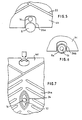
- FIG 4 shows a first embodiment of the invention, in which a plate 4 a is constructed generally as seem in Figure 2, a stack of the plates 4a being assembled together to form a plate heat exchanger as seen in Figure 1.
- a tie bar 16 extends through the hanging eye 25a.
- the tie bar 16 is positioned near and below the hanging rail bifurcation 28.
- the hanging eye 25 a may be enlarged downwardly compared to the Figure 2 arrangement, to provide room for the tie bar 16. It can be seen from Figure 2 that the usual plate design provides space for enlargement of the hanging eye in this direction without encroaching on the flow space 24.
- the corresponding follower (not shown) may have an eye shaped to receive snugly the tie bar 16, so that a tightening nut can bear on the follower, or a tommy bar, washer plate, or other means may be provided.
- Figure 5 shows a second embodiment of the invention, in which a tie bar 16 is positioned in the lower guide eye 26 a .
- the guide eye 26 a may be extended upwardly if necessary to accommodate the tie bar 16 without encroaching on the flow space.
- the guide rail 8 may be another cross-sectional shape, such as square, to offer greater space for the tie bar 16.
- Figure 6 shows a third embodiment of the invention, in which a tie bar 16 passes through the bottom-rail 8 a , the rail 8 a being hollow, and telescoped or compressible to allow tightening of the tie bar 16 against the follower.
- Figure 7 shows a fourth embodiment in which at least one tie bar 16 passes through apertures 32 in the plates 4 d , in a position surrounded by the flow spaces 24 a and separated thereform by a seal 34, such as for example a metal or an elastomeric gasket, or a welded or brazed seal.
- a seal 34 such as for example a metal or an elastomeric gasket, or a welded or brazed seal.
- a tie bar 16 may be wholly positioned, when viewed in cross-section, within a cut-out, or it may protrude outside of the cut-out and hence outside of the plate area. It is particularly preferred to use, for the tie bars, cut-outs or apertures on the vertical centre line of the plates.
Landscapes
- Engineering & Computer Science (AREA)
- Physics & Mathematics (AREA)
- Thermal Sciences (AREA)
- Mechanical Engineering (AREA)
- General Engineering & Computer Science (AREA)
- Heat-Exchange Devices With Radiators And Conduit Assemblies (AREA)
Claims (8)
- Plattenwärmetauscher mit einem Plattenstapel (4a, 4d), die mittels Verbindungsstangen (16) zwischen einem Kopf (10) und einem Mitnehmer (14) gegeneinander gepresst sind, wobei mindestens eine Platte einen oberen und einen unteren Ausschnitt (25a, 26a, 26b) aufweist, wobei die Ausschnitte jeweils innerhalb des Plattenbereichs ausgebildet sind und durch den äußeren Umfang der Platte begrenzt werden, dadurch gekennzeichnet, dass die Platten obere und untere Ausschnitte (25a, 26a, 26b) aufweisen, mit welchen die Platten zwischen oberen und unteren Schienen (6, 8) in ihrer Position halten, und dass zumindest eine Verbindungsstange sich durch einen der oberen und unteren Ausschnitte erstreckt.
- Plattenwärmetauscher nach Anspruch 1, dadurch gekennzeichnet, dass eine erste Verbindungsstange sich durch die oberen Ausschnitte (26a) der Platten erstreckt und eine zweite Verbindungsstange sich durch die unteren Ausschnitte (26b) der Platten erstreckt.
- Plattenwärmetauscher nach Anspruch 1 oder 2, dadurch gekennzeichnet, dass die Verbindungsstange in den oberen Ausschnitten unterhalb der oberen Schiene (6) positioniert ist.
- Plattenwärmetauscher nach Anspruch 3, dadurch gekennzeichnet, dass die obere Schiene (6) an ihrem unteren Ende gegabelt ist, und dass die Verbindungsstange (16) in der Gabelabzweigung der Gabelung (30) positioniert ist.
- Plattenwärmetauscher nach einem der Ansprüche 1 bis 4, dadurch gekennzeichnet, dass die oder eine Verbindungsstange sich durch die unteren Ausschnitte erstreckt und über der unteren Schiene (9) positioniert ist.
- Plattenwärmetauscher nach einem der Ansprüche 1 bis 5, dadurch gekennzeichnet, dass eine der Schienen (8a) rohrförmig ist und sich eine Verbindungsstange durch eine der Schienen erstreckt.
- Plattenwärmetauscher mit einem Plattenstapel (4a, 4d), die zwischen einem Kopf (10) und einem Mitnehmer (14) mittels Verbindungsstangen (16) gegeneinander gepresst werden, dadurch gekennzeichnet, dass die Platten obere und untere Ausschnitte (25a, (26a, 26b) aufweisen, welche die Platten zwischen oberen und unteren Schienen in ihrer Position halten, und dass zumindest eine Verbindungsstange (16) sich durch eine Öffnung (32) im Korpus jeder einzelnen Platte in der Weise erstreckt, dass sie durch die Platten hindurch in einem Bereich geführt ist, der von den Fließräumen zwischen den Platten umgeben ist, wobei jede Öffnung (32) durch eine Dichtung (34) gegenüber den Fließräumen abgedichtet ist.
- Plattenwärmetauscher nach einem der vorhergehenden Ansprüche, dadurch gekennzeichnet, dass die Verbindungsstange (16) im wesentlichen auf der vertikalen Mittellinie des Wärmetauschers positioniert ist.
Applications Claiming Priority (3)
| Application Number | Priority Date | Filing Date | Title |
|---|---|---|---|
| GB9301021 | 1993-01-20 | ||
| GB9301021A GB2274509B (en) | 1993-01-20 | 1993-01-20 | Plate heat exchanger |
| PCT/GB1994/000095 WO1994017354A1 (en) | 1993-01-20 | 1994-01-18 | Plate heat exchanger |
Publications (3)
| Publication Number | Publication Date |
|---|---|
| EP0680593A1 EP0680593A1 (de) | 1995-11-08 |
| EP0680593B1 EP0680593B1 (de) | 1996-11-06 |
| EP0680593B2 true EP0680593B2 (de) | 2002-01-09 |
Family
ID=10728965
Family Applications (1)
| Application Number | Title | Priority Date | Filing Date |
|---|---|---|---|
| EP94904278A Expired - Lifetime EP0680593B2 (de) | 1993-01-20 | 1994-01-18 | Plattenwärmetauscher |
Country Status (7)
| Country | Link |
|---|---|
| US (1) | US5740859A (de) |
| EP (1) | EP0680593B2 (de) |
| AU (1) | AU5840694A (de) |
| DE (1) | DE69400867T3 (de) |
| DK (1) | DK0680593T4 (de) |
| GB (2) | GB2312042B (de) |
| WO (1) | WO1994017354A1 (de) |
Families Citing this family (7)
| Publication number | Priority date | Publication date | Assignee | Title |
|---|---|---|---|---|
| SE522500C2 (sv) * | 2002-09-17 | 2004-02-10 | Valeo Engine Cooling Ab | Anordning vid en plattvärmeväxlare |
| US6899163B2 (en) * | 2003-03-24 | 2005-05-31 | Apv North America, Inc. | Plate heat exchanger and method for using the same |
| US20090291188A1 (en) * | 2008-05-22 | 2009-11-26 | Milne Jeffrey J | Vegetable protein meat analogues and methods of making the same |
| SE533583C2 (sv) * | 2009-03-13 | 2010-10-26 | Alfa Laval Corp Ab | Plattvärmeväxlare |
| KR101307786B1 (ko) | 2012-04-04 | 2013-09-12 | 동아대학교 산학협력단 | 판형 열교환기 |
| BR112015007767B1 (pt) | 2012-10-30 | 2020-11-10 | Alfa Laval Corporate Ab | gaxeta para arranjo e vedação entre uma primeira e uma segunda placa de trocador de calor adjacentes, e, conjunto |
| US12352511B2 (en) * | 2022-10-04 | 2025-07-08 | Spx Flow, Inc. | Telescoping cover for a threaded rod |
Family Cites Families (17)
| Publication number | Priority date | Publication date | Assignee | Title |
|---|---|---|---|---|
| CA622045A (en) * | 1961-06-13 | Aktiebolaget Separator | Device for suspending plates in heat exchanger | |
| GB249184A (en) * | 1925-06-23 | 1926-03-25 | Harry Gibbs | Improvements in steam condensing plant |
| US1727124A (en) * | 1928-04-10 | 1929-09-03 | Foster Wheeler Corp | Plate air-heater construction |
| GB517312A (en) * | 1937-05-22 | 1940-01-25 | Ruben Alef Persson | Improvements in or relating to plate heat exchange apparatus |
| US2601974A (en) * | 1939-12-09 | 1952-07-01 | Separator Ab | Plate heat exchanger |
| GB637225A (en) * | 1946-03-19 | 1950-05-17 | Kenneth Arthur Spearing | Improvements in and relating to heat interchangers |
| US2621028A (en) * | 1947-02-24 | 1952-12-09 | Cherry Burrell Corp | Plate type heat exchanger support |
| US2639126A (en) * | 1947-02-24 | 1953-05-19 | Cherry Burrell Corp | Plate apparatus and press |
| US2754093A (en) * | 1952-08-21 | 1956-07-10 | Separator Ab | Suspension of plates in plate heat exchangers |
| GB1199067A (en) * | 1967-11-24 | 1970-07-15 | Rosenblads Patenter Ab | An Arrangement in Heat Exchangers of the Plate Type |
| DE2923913A1 (de) * | 1979-06-13 | 1980-12-18 | Hoechst Ag | Anschlussvorrichtung fuer flache hohlkoerper |
| GB2052038B (en) * | 1979-07-06 | 1983-09-07 | Apv Co Ltd | Plate heat exchangers |
| GB2065289B (en) * | 1979-12-13 | 1983-10-12 | Apv Co Ltd | Hanging arrangement for plate heat exchanger |
| GB2162630B (en) * | 1984-08-03 | 1987-10-21 | Atomic Energy Authority Uk | A heat exchanger |
| GB2208005A (en) * | 1987-08-07 | 1989-02-15 | Apv Uk | Plate heat transfer apparatus |
| IT1239640B (it) * | 1990-02-22 | 1993-11-11 | Recuperator S R L | Serie di elementi di tipo modulare,per la tenuta meccanica di scambiatori di calore a piastre, operanti a flussi incrociati, per effluenti gassosi |
| SE467275B (sv) * | 1990-05-02 | 1992-06-22 | Alfa Laval Thermal Ab | Loedd dubbelvaeggig plattvaermevaexlare med bockade kanter |
-
1993
- 1993-01-20 GB GB9715224A patent/GB2312042B/en not_active Expired - Fee Related
- 1993-01-20 GB GB9301021A patent/GB2274509B/en not_active Expired - Fee Related
-
1994
- 1994-01-18 DK DK94904278T patent/DK0680593T4/da active
- 1994-01-18 WO PCT/GB1994/000095 patent/WO1994017354A1/en not_active Ceased
- 1994-01-18 AU AU58406/94A patent/AU5840694A/en not_active Abandoned
- 1994-01-18 EP EP94904278A patent/EP0680593B2/de not_active Expired - Lifetime
- 1994-01-18 US US08/491,924 patent/US5740859A/en not_active Expired - Fee Related
- 1994-01-18 DE DE69400867T patent/DE69400867T3/de not_active Expired - Fee Related
Also Published As
| Publication number | Publication date |
|---|---|
| DE69400867T3 (de) | 2002-10-17 |
| EP0680593A1 (de) | 1995-11-08 |
| DE69400867T2 (de) | 1997-03-13 |
| WO1994017354A1 (en) | 1994-08-04 |
| GB2312042A (en) | 1997-10-15 |
| GB2312042B (en) | 1997-11-26 |
| GB2274509B (en) | 1997-09-17 |
| DK0680593T3 (da) | 1997-03-10 |
| GB9715224D0 (en) | 1997-09-24 |
| GB9301021D0 (en) | 1993-03-10 |
| GB2274509A (en) | 1994-07-27 |
| DE69400867D1 (de) | 1996-12-12 |
| US5740859A (en) | 1998-04-21 |
| AU5840694A (en) | 1994-08-15 |
| DK0680593T4 (da) | 2002-04-22 |
| EP0680593B1 (de) | 1996-11-06 |
Similar Documents
| Publication | Publication Date | Title |
|---|---|---|
| EP0680593B2 (de) | Plattenwärmetauscher | |
| US6062305A (en) | Plate heat exchanger | |
| DE60110757T2 (de) | Plattenpaket für einen Plattenwärmetauscher | |
| EP0448991A3 (en) | Heat exchanger | |
| DE60025372D1 (de) | Wärmetauscher und dazugehöriges wärmeaustauschmodul | |
| CA2039020A1 (en) | Plate heat exchanger | |
| JPH01503558A (ja) | 恒久的に接合されたプレート式熱交換器 | |
| US4250786A (en) | Punching tool | |
| US4813478A (en) | Plate heat exchanger | |
| EP0164391B1 (de) | Wärmeaustauscherplatte | |
| GB1473977A (en) | Space heating radiator and method for its manufacture | |
| EP0350229A1 (de) | Stützrahmen für Filterelemente | |
| US4646821A (en) | Plate elements and gaskets at plate heat exchangers or plate filters | |
| DE20208748U1 (de) | Wärmeaustauschernetz, insbesondere für Hochtemperaturanwendungen | |
| EP0096688A1 (de) | Plattenwärmeaustauscher. | |
| CN213375392U (zh) | 一种多功能滤网 | |
| CN217191975U (zh) | 一种分格式冲孔铝板 | |
| EP0033201A2 (de) | Gestellbauteile eines Wärmetauschers | |
| AU3543099A (en) | Heat exchanger installation | |
| CN113339931A (zh) | 一种空气净化器外壳及其一体加工成型的方法 | |
| GB2151347A (en) | Plate heat exchangers | |
| DE2438281A1 (de) | Einrichtung zum abdichten der zwischen zwei benachbarten platten eines waermetauschers eingeschlossenen raeume | |
| DE60019456T2 (de) | Plattenwärmetauscher | |
| CN217083020U (zh) | 一种冰箱 | |
| CN217799849U (zh) | 滤网焊接工装 |
Legal Events
| Date | Code | Title | Description |
|---|---|---|---|
| PUAI | Public reference made under article 153(3) epc to a published international application that has entered the european phase |
Free format text: ORIGINAL CODE: 0009012 |
|
| 17P | Request for examination filed |
Effective date: 19950726 |
|
| AK | Designated contracting states |
Kind code of ref document: A1 Designated state(s): DE DK FR SE |
|
| GRAG | Despatch of communication of intention to grant |
Free format text: ORIGINAL CODE: EPIDOS AGRA |
|
| GRAH | Despatch of communication of intention to grant a patent |
Free format text: ORIGINAL CODE: EPIDOS IGRA |
|
| 17Q | First examination report despatched |
Effective date: 19960301 |
|
| GRAH | Despatch of communication of intention to grant a patent |
Free format text: ORIGINAL CODE: EPIDOS IGRA |
|
| GRAA | (expected) grant |
Free format text: ORIGINAL CODE: 0009210 |
|
| RAP1 | Party data changed (applicant data changed or rights of an application transferred) |
Owner name: APV UK PLC |
|
| AK | Designated contracting states |
Kind code of ref document: B1 Designated state(s): DE DK FR SE |
|
| REF | Corresponds to: |
Ref document number: 69400867 Country of ref document: DE Date of ref document: 19961212 |
|
| ET | Fr: translation filed | ||
| REG | Reference to a national code |
Ref country code: DK Ref legal event code: T3 |
|
| PLBQ | Unpublished change to opponent data |
Free format text: ORIGINAL CODE: EPIDOS OPPO |
|
| PLBI | Opposition filed |
Free format text: ORIGINAL CODE: 0009260 |
|
| PLBF | Reply of patent proprietor to notice(s) of opposition |
Free format text: ORIGINAL CODE: EPIDOS OBSO |
|
| 26 | Opposition filed |
Opponent name: ALFA LAVAL AB Effective date: 19970806 |
|
| PLBF | Reply of patent proprietor to notice(s) of opposition |
Free format text: ORIGINAL CODE: EPIDOS OBSO |
|
| PLBF | Reply of patent proprietor to notice(s) of opposition |
Free format text: ORIGINAL CODE: EPIDOS OBSO |
|
| PLAW | Interlocutory decision in opposition |
Free format text: ORIGINAL CODE: EPIDOS IDOP |
|
| APAC | Appeal dossier modified |
Free format text: ORIGINAL CODE: EPIDOS NOAPO |
|
| APAE | Appeal reference modified |
Free format text: ORIGINAL CODE: EPIDOS REFNO |
|
| APAC | Appeal dossier modified |
Free format text: ORIGINAL CODE: EPIDOS NOAPO |
|
| APAC | Appeal dossier modified |
Free format text: ORIGINAL CODE: EPIDOS NOAPO |
|
| RAP2 | Party data changed (patent owner data changed or rights of a patent transferred) |
Owner name: APV UK LIMITED |
|
| PLAW | Interlocutory decision in opposition |
Free format text: ORIGINAL CODE: EPIDOS IDOP |
|
| PUAH | Patent maintained in amended form |
Free format text: ORIGINAL CODE: 0009272 |
|
| STAA | Information on the status of an ep patent application or granted ep patent |
Free format text: STATUS: PATENT MAINTAINED AS AMENDED |
|
| 27A | Patent maintained in amended form |
Effective date: 20020109 |
|
| AK | Designated contracting states |
Kind code of ref document: B2 Designated state(s): DE DK FR SE |
|
| REG | Reference to a national code |
Ref country code: DK Ref legal event code: T4 |
|
| ET3 | Fr: translation filed ** decision concerning opposition | ||
| PGFP | Annual fee paid to national office [announced via postgrant information from national office to epo] |
Ref country code: FR Payment date: 20021231 Year of fee payment: 10 |
|
| PGFP | Annual fee paid to national office [announced via postgrant information from national office to epo] |
Ref country code: DE Payment date: 20030122 Year of fee payment: 10 |
|
| PGFP | Annual fee paid to national office [announced via postgrant information from national office to epo] |
Ref country code: DK Payment date: 20030127 Year of fee payment: 10 |
|
| PG25 | Lapsed in a contracting state [announced via postgrant information from national office to epo] |
Ref country code: DK Free format text: LAPSE BECAUSE OF NON-PAYMENT OF DUE FEES Effective date: 20040202 |
|
| PG25 | Lapsed in a contracting state [announced via postgrant information from national office to epo] |
Ref country code: DE Free format text: LAPSE BECAUSE OF NON-PAYMENT OF DUE FEES Effective date: 20040803 |
|
| REG | Reference to a national code |
Ref country code: DK Ref legal event code: EBP |
|
| PG25 | Lapsed in a contracting state [announced via postgrant information from national office to epo] |
Ref country code: FR Free format text: LAPSE BECAUSE OF NON-PAYMENT OF DUE FEES Effective date: 20040930 |
|
| REG | Reference to a national code |
Ref country code: FR Ref legal event code: ST |
|
| APAH | Appeal reference modified |
Free format text: ORIGINAL CODE: EPIDOSCREFNO |
|
| PGFP | Annual fee paid to national office [announced via postgrant information from national office to epo] |
Ref country code: SE Payment date: 20110127 Year of fee payment: 18 |
|
| REG | Reference to a national code |
Ref country code: SE Ref legal event code: EUG |
|
| PG25 | Lapsed in a contracting state [announced via postgrant information from national office to epo] |
Ref country code: SE Free format text: LAPSE BECAUSE OF NON-PAYMENT OF DUE FEES Effective date: 20120119 |