EP0680112A2 - Appareil radio et antenne avec connexion directe - Google Patents
Appareil radio et antenne avec connexion directe Download PDFInfo
- Publication number
- EP0680112A2 EP0680112A2 EP95101846A EP95101846A EP0680112A2 EP 0680112 A2 EP0680112 A2 EP 0680112A2 EP 95101846 A EP95101846 A EP 95101846A EP 95101846 A EP95101846 A EP 95101846A EP 0680112 A2 EP0680112 A2 EP 0680112A2
- Authority
- EP
- European Patent Office
- Prior art keywords
- antenna
- radio
- computer
- gps receiver
- card
- Prior art date
- Legal status (The legal status is an assumption and is not a legal conclusion. Google has not performed a legal analysis and makes no representation as to the accuracy of the status listed.)
- Withdrawn
Links
- 230000008878 coupling Effects 0.000 claims description 15
- 238000010168 coupling process Methods 0.000 claims description 15
- 238000005859 coupling reaction Methods 0.000 claims description 15
- 238000004891 communication Methods 0.000 claims description 9
- 230000013011 mating Effects 0.000 claims description 4
- 238000003780 insertion Methods 0.000 claims description 3
- 230000037431 insertion Effects 0.000 claims description 3
- 238000000034 method Methods 0.000 description 9
- 230000005540 biological transmission Effects 0.000 description 6
- 239000003989 dielectric material Substances 0.000 description 6
- 238000007373 indentation Methods 0.000 description 5
- 230000002829 reductive effect Effects 0.000 description 5
- 230000015556 catabolic process Effects 0.000 description 4
- 238000006731 degradation reaction Methods 0.000 description 4
- 239000004020 conductor Substances 0.000 description 3
- 239000000047 product Substances 0.000 description 3
- 230000003321 amplification Effects 0.000 description 2
- 238000010276 construction Methods 0.000 description 2
- 238000013461 design Methods 0.000 description 2
- 238000005516 engineering process Methods 0.000 description 2
- 230000006870 function Effects 0.000 description 2
- 238000012423 maintenance Methods 0.000 description 2
- 229910052751 metal Inorganic materials 0.000 description 2
- 239000002184 metal Substances 0.000 description 2
- 239000007769 metal material Substances 0.000 description 2
- 238000003199 nucleic acid amplification method Methods 0.000 description 2
- 239000000758 substrate Substances 0.000 description 2
- RYGMFSIKBFXOCR-UHFFFAOYSA-N Copper Chemical compound [Cu] RYGMFSIKBFXOCR-UHFFFAOYSA-N 0.000 description 1
- 239000000853 adhesive Substances 0.000 description 1
- 230000001070 adhesive effect Effects 0.000 description 1
- 230000002411 adverse Effects 0.000 description 1
- 229910052782 aluminium Inorganic materials 0.000 description 1
- XAGFODPZIPBFFR-UHFFFAOYSA-N aluminium Chemical compound [Al] XAGFODPZIPBFFR-UHFFFAOYSA-N 0.000 description 1
- 230000000712 assembly Effects 0.000 description 1
- 238000000429 assembly Methods 0.000 description 1
- 239000000919 ceramic Substances 0.000 description 1
- 229910010293 ceramic material Inorganic materials 0.000 description 1
- 239000002131 composite material Substances 0.000 description 1
- 229910052802 copper Inorganic materials 0.000 description 1
- 239000010949 copper Substances 0.000 description 1
- 230000003247 decreasing effect Effects 0.000 description 1
- 230000000694 effects Effects 0.000 description 1
- 239000011152 fibreglass Substances 0.000 description 1
- 231100001261 hazardous Toxicity 0.000 description 1
- 238000009434 installation Methods 0.000 description 1
- 230000002452 interceptive effect Effects 0.000 description 1
- 230000000670 limiting effect Effects 0.000 description 1
- 239000000463 material Substances 0.000 description 1
- 238000004806 packaging method and process Methods 0.000 description 1
- 238000012545 processing Methods 0.000 description 1
- 239000000126 substance Substances 0.000 description 1
- 239000013589 supplement Substances 0.000 description 1
- 230000000153 supplemental effect Effects 0.000 description 1
Images


Classifications
-
- H—ELECTRICITY
- H01—ELECTRIC ELEMENTS
- H01Q—ANTENNAS, i.e. RADIO AERIALS
- H01Q1/00—Details of, or arrangements associated with, antennas
- H01Q1/12—Supports; Mounting means
- H01Q1/22—Supports; Mounting means by structural association with other equipment or articles
- H01Q1/2258—Supports; Mounting means by structural association with other equipment or articles used with computer equipment
- H01Q1/2275—Supports; Mounting means by structural association with other equipment or articles used with computer equipment associated to expansion card or bus, e.g. in PCMCIA, PC cards, Wireless USB
-
- G—PHYSICS
- G01—MEASURING; TESTING
- G01S—RADIO DIRECTION-FINDING; RADIO NAVIGATION; DETERMINING DISTANCE OR VELOCITY BY USE OF RADIO WAVES; LOCATING OR PRESENCE-DETECTING BY USE OF THE REFLECTION OR RERADIATION OF RADIO WAVES; ANALOGOUS ARRANGEMENTS USING OTHER WAVES
- G01S19/00—Satellite radio beacon positioning systems; Determining position, velocity or attitude using signals transmitted by such systems
- G01S19/01—Satellite radio beacon positioning systems transmitting time-stamped messages, e.g. GPS [Global Positioning System], GLONASS [Global Orbiting Navigation Satellite System] or GALILEO
- G01S19/13—Receivers
- G01S19/35—Constructional details or hardware or software details of the signal processing chain
- G01S19/36—Constructional details or hardware or software details of the signal processing chain relating to the receiver frond end
-
- G—PHYSICS
- G01—MEASURING; TESTING
- G01S—RADIO DIRECTION-FINDING; RADIO NAVIGATION; DETERMINING DISTANCE OR VELOCITY BY USE OF RADIO WAVES; LOCATING OR PRESENCE-DETECTING BY USE OF THE REFLECTION OR RERADIATION OF RADIO WAVES; ANALOGOUS ARRANGEMENTS USING OTHER WAVES
- G01S19/00—Satellite radio beacon positioning systems; Determining position, velocity or attitude using signals transmitted by such systems
- G01S19/01—Satellite radio beacon positioning systems transmitting time-stamped messages, e.g. GPS [Global Positioning System], GLONASS [Global Orbiting Navigation Satellite System] or GALILEO
- G01S19/13—Receivers
- G01S19/35—Constructional details or hardware or software details of the signal processing chain
- G01S19/37—Hardware or software details of the signal processing chain
-
- H—ELECTRICITY
- H01—ELECTRIC ELEMENTS
- H01Q—ANTENNAS, i.e. RADIO AERIALS
- H01Q23/00—Antennas with active circuits or circuit elements integrated within them or attached to them
-
- Y—GENERAL TAGGING OF NEW TECHNOLOGICAL DEVELOPMENTS; GENERAL TAGGING OF CROSS-SECTIONAL TECHNOLOGIES SPANNING OVER SEVERAL SECTIONS OF THE IPC; TECHNICAL SUBJECTS COVERED BY FORMER USPC CROSS-REFERENCE ART COLLECTIONS [XRACs] AND DIGESTS
- Y10—TECHNICAL SUBJECTS COVERED BY FORMER USPC
- Y10S—TECHNICAL SUBJECTS COVERED BY FORMER USPC CROSS-REFERENCE ART COLLECTIONS [XRACs] AND DIGESTS
- Y10S439/00—Electrical connectors
- Y10S439/916—Antenna
Definitions
- the present invention relates to radio and antenna structures and connectors, and methods of implementing them.
- the present invention is directed to such structures, connectors, and methods for improving signal reception and transmission by a computer-based device which utilizes the global positioning system (GPS).
- GPS global positioning system
- the GPS is a space-based radio navigation system that provides worldwide, all-weather determinations of position, altitude, time and velocity.
- the GPS is implemented using a passive radio receiver and is available to a virtually unlimited number of users.
- the GPS radio receiver detects and receives precise reference signals from a constellation of 24 GPS satellites orbiting the earth.
- Low cost GPS receivers have been available for several years in specific GPS-dedicated products. Typically, these GPS application-specific products have included such basic computer components of a display, keyboard, power supply, processor and housing. Accordingly, it has been recognized that portable computers and the like are an excellent platform to utilize GPS technology.
- PCMCIA Personal Computer Memory Card International Association
- PDA personal digital assistant
- Antenna placement has been found to raise certain issues with regard to the particular positioning configuration of the antenna to maximize visibility of the antenna to the GPS satellites, yet minimize cumbersome external components and cables. Although such considerations are evident in a variety of wireless communications applications, an effective antenna placement and mounting structure has yet to be developed which provides for both simple and easy mounting and removal, while concurrently maximizing signal reception and quality.
- Coaxial cables tend to introduce undesirable signal degradation attributable to signal attenuation through the cable, added receiver system noise, as well as reflection losses attributable to mismatched impedances. Reflection losses are apparent transmission losses across the cable which result when the impedance of a load, e.g., an antenna, is mismatched with that of a generator, such as a radio transmitter. Consequently, transmission losses on the line result when a portion of the energy is reflected due to the discontinuity of the mismatched impedances in the transmission line.
- a load e.g., an antenna
- a conventional cable configuration may include a GPS radio receiver 100 coupled to a PCMCIA interface 102 via a cable arrangement, as illustrated in Figure 1.
- the PCMCIA interface 102 is coupled to the GPS receiver 100 by a serial interface port cable 104.
- a patch-type antenna 106 is coupled to the receiver 100 via a coaxial cable and connector arrangement 108.
- this coaxial cable arrangement 108 may introduce reflection and transmission losses of approximately 2.5 dB to 5 dB maximum at 1575 megahertz (MHz).
- MHz megahertz
- a radio is directly coupled to a computer via a plug-in connection or receiving slot such as a PCMCIA interface slot.
- An antenna is mounted on the top surface of the radio via a coaxial connector having a first part and a second part.
- the antenna has a substantially flat bottom surface to which is coupled the first part of the coaxial connector.
- the second part of the coaxial connector is affixed to the top surface of the radio. Accordingly, when the first and second parts of the coaxial connector are affixed to the corresponding surfaces of the antenna and the radio, the top surface of the radio directly faces and is adjacent to the bottom surface of the antenna.
- the antenna comprises a patch-type antenna element having a size and shape that conforms to and is compatible with the size and shape of the radio.
- the patch antenna may be rigid or malleable, depending upon the particular radio operating conditions.
- the second part of the coaxial connector, which is coupled to the top surface of the radio is contained in an indent in the surface of the radio, and the first part of the coaxial connector coupled to the bottom surface of the patch antenna mates directly to the second part of the coaxial connector. Accordingly, the need for external and internal coaxial cables is eliminated, while signal degradation and losses inherently produced when using such cables can be significantly reduced.
- Figure 1 is a perspective view of a prior art antenna arrangement.
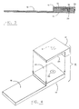
- Figure 2 is a perspective view of a direct connect antenna according to a preferred embodiment of the present invention.
- Figure 3 is a side cross-sectional view of a mounted direct connect antenna along lines 3-3 indicated in the embodiment of Figure 2.
- Figure 4 is a perspective view of an alternate embodiment of the present invention.
- a direct connect radio and antenna structure in accordance with an embodiment of the present invention is indicated generally at 10 in Figure 2.
- the radio and antenna configuration includes a radio coupled to a plug-in computer-adaptable module or card 16, such as a PCMCIA interface card, and a directly connectable antenna 12.
- the radio component 14 comprises a GPS radio receiver.
- the receiver 14 may be directly coupled to a patch-type antenna 12.
- embodiments of the present invention provide GPS receiver capabilities embedded within a PCMCIA format.
- Antenna embodiments of the present invention provide for substantially reduced RF signal degradation typically attributable to distributed cable losses and attenuation introduced by conventional antenna cable arrangements.
- coaxial cables are typical sources of cable losses.
- embodiments of the present invention are directed to decreasing the amount and effects of coaxial cable reflection losses and distributed losses by eliminating unnecessary cabling. Consequently, the need to match the characteristic impedances of the interconnected components is likewise eliminated.
- embodiments of the present invention provide for an integrated antenna arrangement which allows for uncomplicated mounting of the antenna to a radio, and immediate installation of the integrated PCMCIA card and radio within the host computer.
- preferred embodiments of the present invention include a patch-type antenna 12 which can be directly coupled to a GPS radio receiver 14.
- the receiver 14 is coupled to and extends from a PCMCIA memory interface card 16.
- the antenna 12 may be mounted on, and thus supported by, the GPS receiver 14, as illustrated in Figures 2 and 3.
- the PC card 16 is an extended-form PCMCIA compliant Type II interface and is approximately half as thick as the GPS receiver 14.
- the PCMCIA card 16 may be thicker or thinner than that shown.
- the PC card 16 includes an application specific integrated circuit (ASIC), a universal asynchronous receiver transmitter (UART), and a read only memory (ROM).
- ASIC application specific integrated circuit
- UART universal asynchronous receiver transmitter
- ROM read only memory
- the ASIC for example, performs logic functions necessary for particular applications to interface the PCMCIA standard with the host computer.
- the PC card and GPS receiver arrangement produces a serial output
- the UART provides a means of converting the serial data to a digital parallel format across a PCMCIA bus (not shown).
- the UART acts as a standard serial interface.
- the antenna 12 is mounted to the radio receiver 14 via a two-part coaxial connector 18 and 20.
- Half of the coaxial connector 18, e.g., the male or female part, is defined on one surface of the antenna 12.
- the opposing part of the coaxial connector 20 is formed in an adjacent surface of the GPS receiver.
- the male and female components 18 and 20 of the coaxial connector are affixed to the antenna 12 and GPS receiver 14, respectively.
- the female component 18 is mounted to the underside 24 of the antenna 12.
- the female component 18 protrudes from the lower surface 24 of the antenna 12 for coupling with the male component 20 formed in the upper surface 22 of the GPS receiver 14.
- the male connector 20 is formed as an indent in the upper surface 22 of the receiver 14. In this way, the protruding female connector 18 can be quickly and simply inserted into the male connector 20 to provide a tight snap-fit in which little or no space is left between the surfaces 24 and 22 of the antenna 12 and the receiver 14, respectively.
- Such an arrangement allows minimal movement and shifting of the antenna relative to the GPS receiver and, consequently, substantially reduces the potential for breakage or loss of the received radio frequency (RF) signal.
- the particular connector configuration provides a repeatable ground plane for the antenna.
- the arrangement of the male and female coaxial connector components may be reversed, such that the male component is attached to the antenna, while the female component is coupled to the GPS receiver.
- either the male or female coaxial connector part may protrude from or be contained within its respective mounting surface.
- the male connector may be mounted to the lower surface 24 of the antenna 12 and protrude therefrom for insertion into an associated female connector defined within the upper surface 22 of the GPS receiver 14.
- connection arrangements in addition to coaxial connectors, may be used.
- the radio and antenna may be directly connected via single conductor cabling.
- the radio and antenna may be connected directly by a single line connection scheme.
- the male and female coaxial connectors may both be arranged to protrude slightly from the lower and upper surfaces of the antenna and the GPS receiver 14, respectively.
- the antenna 12 may be thinner than the GPS receiver 14, the connector component carried by the antenna 12 is preferably externally attached or otherwise protrudes from the lower surface 24 of the antenna 12. Such construction is preferred to avoid interference between the coaxial connector attachment and the antenna element disposed within the antenna 12.
- the antenna 12 is a patch-type antenna in which a metal material 13, such as copper, aluminum, or a composite substance, is bonded to opposite sides of a high-dielectric material (not shown) and encased within a radome structure 26.
- the dielectric material may comprise a ceramic or fiberglass substrate.
- the external surface of the metal material 13, which receives the RF signals, is etched to obtain the optimum receiving characteristics based on the dielectric constant of the materials used to form the substrate and the radome, the size of the patch element 13, and the received frequency. This arrangement helps to prevent resonant frequency drift with temperature variations. Consequently, the signal reception area may be maximized, while the antenna size and unnecessary protrusion are reduced.
- the coaxial connector components 18 and 20 are preferably mounted on the lower and upper surfaces of the antenna and GPS receiver, respectively. Accordingly, the female connector 18 is in contact with the internal conductive material of the antenna 12.
- the male connector 20, which is coupled to an RF interface (not shown) internal to the GPS receiver 14, can then be mated to the female connector 18 with the respective surfaces of the antenna 12 and the receiver 14 facing each other.
- Supplemental fastening devices and interconnecting structures may be implemented to secure the antenna 12 to the receiver 14.
- multiple indentations 40 are provided about the periphery of the antenna 12 for slidable mating with associated receiving slots 42 formed along the sides of the receiver 14.
- the indentation/slot structures act as guides to provide an uncomplicated means of aligning and coupling the two connector halves 18 and 20 together. Furthermore, such alignment prevents mismatching of the connector halves and possible connector damage. Accordingly, a user can easily attach the antenna to the receiver.
- the antenna can be quickly mounted and secured to the receiver without requiring extra careful attention to accurately match together the coaxial connector halves 18 and 20.
- the configuration and structure of the indentation and slot arrangement are particularly described, it will be recognized, however, that a variety of guide or alignment configurations may be employed.
- the antenna 12 may be mounted to the GPS receiver 14 by screws or other semi-permanent devices which supplement the snap-in connection provided by the coaxial connector. Screws generally will not detune the antenna as long as proper design criteria are followed. Such means of affixing the antenna to the GPS receiver or to another object is preferred if permanent or rigid antenna attachment is desired. In still further embodiments, different means such as an adhesive and the like may be used to secure the antenna to the GPS receiver.
- the upper exposed surface of the radome 26 comprises a curved shape, with the underside being relatively flat to conform to the shape of the GPS receiver 14, it will be recognized that other antenna shapes, configurations, and arrangements may be implemented.
- the antenna may be completely flat to minimize wind resistance, e.g., for use in or on a moving vehicle, or malleable to fit around or within limited, defined spaces.
- the antenna may have a variety of shapes or configurations to accommodate the receiver structure and mounting arrangement.
- the antenna 12 has an L-shape which conforms to one of the upper edges of the receiver 14.
- the male and female coaxial connector components may be coupled to either the underside 24 of the antenna 12 and the upper surface 22 of the receiver 14.
- the numerical references to the various elements of Figure 4 are coincident with those of Figures 2 and 3 to indicate that, preferably, the shape of the antenna structure 12 should not affect the direct coupling arrangement of the antenna to the receiver.
- the patch antenna is tuned to match the net impedance of the antenna elements, including the dielectric material, ground plane and receiver input impedance to maximize the signal received by the GPS receiver 14.
- a constant impedance value is matched between the antenna and the GPS receiver.
- While the illustrated embodiment employs a GPS receiver which is thicker than the standard Type II PCMCIA interface card, it will be recognized that further embodiments may employ a substantially thinner or smaller GPS receiver, such that the entire unit can be inserted into the Type II slot.
- the memory card and GPS receiver may be permanently hard-wired into the host computer. The patch antenna may then be directly connected to the receiver components carried within the host computer.
- An apparatus for implementation with a computer having a PCMCIA compliant data interface slot the apparatus for determining a user's position coordinates according to GPS satellite tracking data, comprising: a GPS receiver for receiving satellite tracking data and converting the tracking data into digital data; a PCMCIA compliant data interface card (PC card) having a first end and a second end, wherein the first end is adapted for insertion into the computer data interface slot, the GPS receiver is affixed to the second end, and the PC card includes a serial data interface bus for conducting the digital data from the GPS receiver to the first end of the card.
- PC card PCMCIA compliant data interface card
- the apparatus wherein the GPS receiver is integral with the PC card.
- the apparatus wherein the data interface slot is a PCMCIA Type II slot and the PC card has a Type II thickness such that when the PC card is inserted into the data interface slot, the GPS receiver, mounted to the PC card, is adjacent and external to the computer.
- the apparatus wherein the data interface slot is a PCMCIA Type III slot and the PC card has a Type II thickness such that when the PC card is inserted into the data interface slot, the GPS receiver, mounted to the PC card, fits within the data interface slot.
- An apparatus for receiving or transmitting radio communication signals comprising: a radio having a top surface; an antenna having top and bottom surfaces; and a connector having a first part and a second part, the first part being affixed to the bottom surface of the antenna and the second part being affixed to the top surface of the radio, such that when the first and second parts are coupled together, the bottom surface of the antenna is directly adjacent the top surface of the radio.
- the apparatus further comprising: a computer having a data interface slot, and a digital interface card (PC card) for digitally coupling the radio to the computer, wherein the radio is mounted to the PC card which is slidably insertable into the data interface slot such that the radio communication signals received and transmitted by the antenna and radio assembly are digitized and processed by the PC card and the computer.
- PC card digital interface card
- the apparatus wherein when the PC card and receiver assembly are inserted into the data interface slot within the computer, the top surface of the antenna is exposed externally from the computer and the radio to receive and transmit the radio communications signals to and from, respectively, the radio.
- the antenna comprises a patch antenna.
- the patch antenna includes a metal conductive element coupled to a high-dielectric material.
- the apparatus wherein the size and shape of the bottom surface of the patch antenna conform to and are compatible with the size and shape of the radio.
- the apparatus further comprising a plurality of elongated slots formed about the outer periphery of the radio, and an associated plurality of elongated protrusions provided about the inner periphery of the antenna, wherein the slots and associated protrusions are configured for slidable mating with each other such that the radio and antenna can be easily aligned and coupled together.
- the apparatus wherein the second part of the connector is disposed within an indent in the top surface of the radio, and the first part of the connector protrudes from the bottom surface of the antenna.
- the apparatus wherein the bottom surface of the antenna and the top surface of the radio are substantially flat such that when the first and second parts of the coaxial connector are coupled together, the substantially flat surfaces of the antenna and radio rest against each other.
- the apparatus wherein the radio has a substantially flat, rectangular shape, and the patch antenna has an L-shaped longitudinal cross-section which conforms to the shape of the radio.
- the connector comprises a coaxial connector.
- the apparatus wherein the data interface slot complies with PCMCIA standards, and the PC card is a PCMCIA compliant interface card.
- a radio frequency signal tracking system for improving RF signal reception and reducing coaxial cable losses, the system comprising: a global positioning system (GPS) radio receiver; a patch antenna coupled to the GPS receiver for receiving satellite signals; a Personal Computer Memory Card International Association (PCMCIA) interface card (PC card) mounted to and extending from the GPS receiver; a host computer for driving the functions of the GPS receiver and the PC card, the host computer having a PCMCIA compliant interface slot for slidably receiving the PC card; and a coaxial connector coupled to the GPS receiver and the patch antenna for directly coupling the GPS receiver and the antenna together without additional cabling, thereby minimizing cable losses and RF signal attenuation, wherein the coaxial connector includes a female part and a male part, either of the female and male parts being affixed to the GPS receiver and the antenna.
- GPS global positioning system
- PCMCIA Personal Computer Memory Card International Association
- the system wherein the GPS receiver and the patch antenna have substantially flat connector surfaces to which are attached the male and female parts of the coaxial connector, such that when the female and male parts are coupled together, the connector surface of the patch antenna is adjacent to and faces the connector surface of the GPS receiver.
- the patch antenna has a surface area which is substantially equal to that of the GPS receiver.
- the system further comprising a cable extension assembly coupled to the female and male parts of the coaxial connector between the GPS receiver and the patch antenna, wherein the cable extension assembly provides for remote positioning of the antenna.
- the patch antenna includes a high dielectric material coupled to a metal conductive material.
- the high dielectric material comprises a ceramic material.
- a method for improving radio frequency signal reception and quality by a GPS receiver and antenna arrangement, the GPS receiver and the patch antenna having connector surfaces comprising the steps of: attaching a first half of a coaxial connector to the connector surface of the antenna; attaching a second half of the coaxial connector to the connector surface of the GPS receiver; and mating the two halves of the coaxial connector together such that the antenna is directly coupled to the GPS receiver, and the connector surfaces of the GPS receiver and the antenna lie directly adjacent and face each other.
- the method wherein the location, speed, and time coordinates of a user are produced, the method further comprising the steps of: coupling a Personal Computer Memory Card International Association (PCMCIA) interface card (PC card) to the GPS receiver; inserting the PC card into a slot provided in a host computer; receiving RF signals; processing the RF signals through the PC card and the host computer to calculate the location, speed and time coordinates of the user; and displaying the location, speed and time coordinates to the user.
- PCMCIA Personal Computer Memory Card International Association
Applications Claiming Priority (2)
| Application Number | Priority Date | Filing Date | Title |
|---|---|---|---|
| US233289 | 1994-04-26 | ||
| US08/233,289 US5606732A (en) | 1994-04-26 | 1994-04-26 | Direct connect radio and antenna assembly |
Publications (2)
| Publication Number | Publication Date |
|---|---|
| EP0680112A2 true EP0680112A2 (fr) | 1995-11-02 |
| EP0680112A3 EP0680112A3 (fr) | 1996-05-22 |
Family
ID=22876655
Family Applications (1)
| Application Number | Title | Priority Date | Filing Date |
|---|---|---|---|
| EP95101846A Withdrawn EP0680112A3 (fr) | 1994-04-26 | 1995-02-10 | Appareil radio et antenne avec connexion directe. |
Country Status (3)
| Country | Link |
|---|---|
| US (1) | US5606732A (fr) |
| EP (1) | EP0680112A3 (fr) |
| JP (1) | JPH07303052A (fr) |
Cited By (9)
| Publication number | Priority date | Publication date | Assignee | Title |
|---|---|---|---|---|
| WO1996023326A1 (fr) * | 1995-01-26 | 1996-08-01 | Symbionics Ltd. | Antennes |
| EP0829923A1 (fr) * | 1996-09-16 | 1998-03-18 | Alcatel Espace | Dispositif à éléments rayonnants |
| US6014113A (en) * | 1996-12-23 | 2000-01-11 | Nokia Mobile Phones Limited | Antenna assembly comprising circuit unit and shield members |
| WO2001037437A2 (fr) * | 1999-11-15 | 2001-05-25 | Psion Connect Limited | Dispositif amovible sans fil |
| EP1128465A2 (fr) * | 2000-02-21 | 2001-08-29 | Sony Corporation | Dispositif de communication sans fil avec une antenne |
| US6525932B1 (en) | 1999-08-18 | 2003-02-25 | Fujitsu Limited | Expansion unit and electronic apparatus |
| KR100408264B1 (ko) * | 1996-08-21 | 2004-04-14 | 삼성전자주식회사 | 컴퓨터 |
| EP1589680A1 (fr) * | 2004-02-17 | 2005-10-26 | Matsushita Electric Works, Ltd | Unit d'antenne |
| EP2068167A3 (fr) * | 2007-12-06 | 2010-06-02 | O2 Micro, Inc. | Ordinateurs portables avec systèmes de navigation satellite intégrés |
Families Citing this family (59)
| Publication number | Priority date | Publication date | Assignee | Title |
|---|---|---|---|---|
| US7064749B1 (en) | 1992-11-09 | 2006-06-20 | Adc Technology Inc. | Portable communicator |
| US7469150B2 (en) * | 1993-04-27 | 2008-12-23 | Broadcom Corporation | Radio card having independent antenna interface supporting antenna diversity |
| US6928302B1 (en) * | 1993-04-27 | 2005-08-09 | Broadcom Corporation | Radio card having independent antenna interface supporting antenna diversity |
| US5519577A (en) * | 1993-12-23 | 1996-05-21 | Symbol Technologies, Inc. | Spread spectrum radio incorporated in a PCMCIA Type II card holder |
| US6295031B1 (en) | 1993-12-23 | 2001-09-25 | Symbol Technologies, Inc. | Memory card assembly having an integral antenna |
| US5832247A (en) * | 1995-12-28 | 1998-11-03 | Trimble Navigation Limited | PCI card for receiving a GPS signal |
| US6072991A (en) * | 1996-09-03 | 2000-06-06 | Raytheon Company | Compact microwave terrestrial radio utilizing monolithic microwave integrated circuits |
| CA2200675C (fr) * | 1997-03-21 | 2003-12-23 | Chen Wu | Structure d'antenne a circuits imprimes utilisee pour la transmission de donnees sans fil |
| US5987547A (en) * | 1997-03-31 | 1999-11-16 | Texas Instruments Incorporated | Network computer with interchangeable hard drive and data transceiver |
| US6018784A (en) * | 1997-07-31 | 2000-01-25 | Trimble Navigation Limited | PCI card for receiving a GPS signal |
| JP3450666B2 (ja) * | 1997-09-11 | 2003-09-29 | 富士通株式会社 | 乗換又は到着予告通知機能付き情報処理装置,乗換又は到着予告用情報送信装置及び情報処理装置における乗換又は到着予告方法並びにコンピュータ読み取り可能な記録媒体 |
| AU708668B2 (en) * | 1997-11-21 | 1999-08-12 | Xybernaut Corporation | A computer structure for accommodating a PC card |
| US5990846A (en) * | 1998-05-28 | 1999-11-23 | Intel Corporation | Self-aligning global positioning system antenna |
| US6286063B1 (en) | 1998-06-08 | 2001-09-04 | Sonigistix Corporation | Microprocessor-controlled broadcast receiver embedded in an external peripheral with digital communications interface for bi-directional communication with a computer remotely located |
| IL125221A0 (en) | 1998-07-06 | 1999-03-12 | Toy Control Ltd | Motion activation using passive sound source |
| IL127569A0 (en) | 1998-09-16 | 1999-10-28 | Comsense Technologies Ltd | Interactive toys |
| WO2000021020A2 (fr) | 1998-10-02 | 2000-04-13 | Comsense Technologies, Ltd. | Carte permettant d'interagir avec un ordinateur |
| US6607136B1 (en) | 1998-09-16 | 2003-08-19 | Beepcard Inc. | Physical presence digital authentication system |
| US7260221B1 (en) | 1998-11-16 | 2007-08-21 | Beepcard Ltd. | Personal communicator authentication |
| US6150961A (en) * | 1998-11-24 | 2000-11-21 | International Business Machines Corporation | Automated traffic mapping |
| US6333703B1 (en) | 1998-11-24 | 2001-12-25 | International Business Machines Corporation | Automated traffic mapping using sampling and analysis |
| US6434648B1 (en) | 1998-12-10 | 2002-08-13 | Smart Modular Technologies, Inc. | PCMCIA compatible memory card with serial communication interface |
| US6522299B2 (en) * | 1999-04-08 | 2003-02-18 | Cypress Semiconductor Corp. | PC card retractable antenna |
| US6466862B1 (en) * | 1999-04-19 | 2002-10-15 | Bruce DeKock | System for providing traffic information |
| FI111420B (fi) * | 1999-05-07 | 2003-07-15 | Nokia Corp | Elektroniikkalaitteen laajennuskortin antennirakenne |
| US6599147B1 (en) * | 1999-05-11 | 2003-07-29 | Socket Communications, Inc. | High-density removable expansion module having I/O and second-level-removable expansion memory |
| US6353870B1 (en) * | 1999-05-11 | 2002-03-05 | Socket Communications Inc. | Closed case removable expansion card having interconnect and adapter circuitry for both I/O and removable memory |
| US6208506B1 (en) | 1999-05-19 | 2001-03-27 | Gei-Jon Pao | Space saving CD-ROM/DVD drive mechanism used with electronic devices |
| US6407709B1 (en) * | 1999-07-16 | 2002-06-18 | Garmin Corporation | Mounting device with integrated antenna |
| US8019609B2 (en) | 1999-10-04 | 2011-09-13 | Dialware Inc. | Sonic/ultrasonic authentication method |
| US7280970B2 (en) * | 1999-10-04 | 2007-10-09 | Beepcard Ltd. | Sonic/ultrasonic authentication device |
| FI19992267A (fi) * | 1999-10-20 | 2001-04-21 | Nokia Mobile Phones Ltd | Laajennuskortti langatonta tiedonsiirtoa varten ja sen antennirakenne |
| AU2002231224A1 (en) | 2000-12-22 | 2002-07-08 | The Charles Stark Draper Laboratory, Inc. | Geographical navigation using multipath wireless navigation signals |
| KR100583483B1 (ko) * | 2001-02-26 | 2006-05-24 | 마츠시타 덴끼 산교 가부시키가이샤 | 통신 카드, 및 통신 기기 |
| SE523715C2 (sv) * | 2001-03-13 | 2004-05-11 | Gigaant Ab Ideon Science & Tec | Antennanordning för montering i ett hölje till en apparat samt sätt för framställning därav |
| US9219708B2 (en) * | 2001-03-22 | 2015-12-22 | DialwareInc. | Method and system for remotely authenticating identification devices |
| US6556170B2 (en) | 2001-04-02 | 2003-04-29 | Fci Americas Technology, Inc. | Retractable and rotatable antenna for an electronic card |
| WO2002100124A1 (fr) * | 2001-06-04 | 2002-12-12 | Gordon Novel | Carte de pc pour destinee a etre utilisee dans un systeme de telecommunications |
| KR100443707B1 (ko) * | 2001-06-05 | 2004-08-09 | 정동회 | 씨에프 타입 지피에스 수신기 |
| WO2003025723A2 (fr) * | 2001-09-19 | 2003-03-27 | Enfora, Inc. | Dispositif radio modulaire tout-en-un |
| JP3723155B2 (ja) * | 2001-11-23 | 2005-12-07 | 三星電子株式会社 | 携帯用コンピュータ |
| US6480146B1 (en) * | 2001-11-29 | 2002-11-12 | Palm, Inc. | Intermittent use of a port in response to location data push |
| US7024224B2 (en) * | 2002-03-05 | 2006-04-04 | Microsoft Corporation | Detachable radio module |
| US20030176179A1 (en) * | 2002-03-18 | 2003-09-18 | Ken Hersey | Wireless local area network and antenna used therein |
| TW575210U (en) * | 2003-03-28 | 2004-02-01 | Micro Star Int Co Ltd | Wireless network device for computer |
| US7834810B2 (en) * | 2004-06-29 | 2010-11-16 | Intel Corporation | Antennae attachable to an electronic device enclosure or other structure |
| GB0418357D0 (en) * | 2004-08-18 | 2004-09-22 | Koninkl Philips Electronics Nv | Gps receiver and related method and apparatus |
| US7262735B2 (en) * | 2004-11-29 | 2007-08-28 | Lexmark International, Inc. | Snap-in antenna assembly for wireless radio circuit card |
| US7908080B2 (en) | 2004-12-31 | 2011-03-15 | Google Inc. | Transportation routing |
| US7973716B2 (en) * | 2005-01-19 | 2011-07-05 | The Charles Stark Draper Laboratory, Inc. | Systems and methods for transparency mapping using multipath signals |
| US8279119B2 (en) * | 2005-01-19 | 2012-10-02 | The Charles Stark Draper Laboratory, Inc. | Systems and methods for transparency mapping using multipath signals |
| WO2006088599A1 (fr) | 2005-01-19 | 2006-08-24 | The Charles Stark Draper Laboratory, Inc. | Systemes et procedes de positionnement a l'aide de signaux multivoies |
| US8577579B2 (en) * | 2010-02-01 | 2013-11-05 | Bendix Commercial Vehicle Systems Llc | Engine control request from adaptive control with braking controller |
| US8907774B2 (en) | 2011-03-01 | 2014-12-09 | Bendix Commercial Vehicle Systems Llc | System and method for monitoring tire condition |
| US8606461B2 (en) | 2011-12-09 | 2013-12-10 | Bendix Commercial Vehicle Systems Llc | System and method for monitoring tire status |
| US9067466B2 (en) | 2013-01-30 | 2015-06-30 | Bendix Commercial Vehicle Systems Llc | Diversity antenna |
| EP2884581B1 (fr) * | 2013-12-10 | 2019-10-16 | Alcatel-Lucent Shanghai Bell Co., Ltd. | Boîtier de système d'antenne et de radôme |
| US20180034154A1 (en) * | 2015-02-19 | 2018-02-01 | Tokyo Cosmos Electric Co., Ltd. | Antenna and communication device |
| US11614545B2 (en) * | 2020-03-26 | 2023-03-28 | Novatel Inc. | Systems and methods for utilizing a connector with an external antenna to utilize multifrequency GNSS functionality of a mobile device |
Citations (6)
| Publication number | Priority date | Publication date | Assignee | Title |
|---|---|---|---|---|
| WO1993016501A1 (fr) * | 1992-02-12 | 1993-08-19 | The Secretary Of State For Defence In Her Britannic Majesty's Government Of The United Kingdom Of Great Britain And Northern Ireland | Equipement de navigation |
| US5239669A (en) * | 1992-02-04 | 1993-08-24 | Trimble Navigation Limited | Coupler for eliminating a hardwire connection between a handheld global positioning system (GPS) receiver and a stationary remote antenna |
| US5272485A (en) * | 1992-02-04 | 1993-12-21 | Trimble Navigation Limited | Microstrip antenna with integral low-noise amplifier for use in global positioning system (GPS) receivers |
| WO1994024722A1 (fr) * | 1993-04-19 | 1994-10-27 | Wireless Access, Inc. | Petite antenne en micro-ruban a court-circuit partiel |
| WO1994026038A1 (fr) * | 1993-04-27 | 1994-11-10 | Norand Corporation | Selection d'antennes multiples et embout d'antenne pour dispositifs informatiques dans lesquels des cartes modem et de radiocommunication sont utilisees |
| WO1994028379A1 (fr) * | 1993-05-28 | 1994-12-08 | Trimble Navigation Limited | Systeme de maintien en position de satellite et pc/104 combine |
Family Cites Families (10)
| Publication number | Priority date | Publication date | Assignee | Title |
|---|---|---|---|---|
| JPS59178511A (ja) * | 1983-03-30 | 1984-10-09 | Hitachi Ltd | 電子機器等の設置構造 |
| JPH02246402A (ja) * | 1989-03-17 | 1990-10-02 | Matsushita Electric Ind Co Ltd | アンテナ装置 |
| US4980694A (en) * | 1989-04-14 | 1990-12-25 | Goldstar Products Company, Limited | Portable communication apparatus with folded-slot edge-congruent antenna |
| US5007863A (en) * | 1990-09-17 | 1991-04-16 | Jialuo Xuan | Module-type multi-function electrical power adapter for automobiles and the like |
| US5198824A (en) * | 1992-01-17 | 1993-03-30 | Texas Instruments Incorporated | High temperature co-fired ceramic integrated phased array packaging |
| US5361061A (en) * | 1992-10-19 | 1994-11-01 | Motorola, Inc. | Computer card data receiver having a foldable antenna |
| JP2897562B2 (ja) * | 1992-11-20 | 1999-05-31 | 株式会社村田製作所 | カード型回線インターフェース装置 |
| US5335276A (en) * | 1992-12-16 | 1994-08-02 | Texas Instruments Incorporated | Communication system and methods for enhanced information transfer |
| US5373149A (en) * | 1993-02-01 | 1994-12-13 | At&T Bell Laboratories | Folding electronic card assembly |
| US5470233A (en) * | 1994-03-17 | 1995-11-28 | Arkenstone, Inc. | System and method for tracking a pedestrian |
-
1994
- 1994-04-26 US US08/233,289 patent/US5606732A/en not_active Expired - Lifetime
-
1995
- 1995-02-10 EP EP95101846A patent/EP0680112A3/fr not_active Withdrawn
- 1995-04-25 JP JP7101250A patent/JPH07303052A/ja not_active Withdrawn
Patent Citations (6)
| Publication number | Priority date | Publication date | Assignee | Title |
|---|---|---|---|---|
| US5239669A (en) * | 1992-02-04 | 1993-08-24 | Trimble Navigation Limited | Coupler for eliminating a hardwire connection between a handheld global positioning system (GPS) receiver and a stationary remote antenna |
| US5272485A (en) * | 1992-02-04 | 1993-12-21 | Trimble Navigation Limited | Microstrip antenna with integral low-noise amplifier for use in global positioning system (GPS) receivers |
| WO1993016501A1 (fr) * | 1992-02-12 | 1993-08-19 | The Secretary Of State For Defence In Her Britannic Majesty's Government Of The United Kingdom Of Great Britain And Northern Ireland | Equipement de navigation |
| WO1994024722A1 (fr) * | 1993-04-19 | 1994-10-27 | Wireless Access, Inc. | Petite antenne en micro-ruban a court-circuit partiel |
| WO1994026038A1 (fr) * | 1993-04-27 | 1994-11-10 | Norand Corporation | Selection d'antennes multiples et embout d'antenne pour dispositifs informatiques dans lesquels des cartes modem et de radiocommunication sont utilisees |
| WO1994028379A1 (fr) * | 1993-05-28 | 1994-12-08 | Trimble Navigation Limited | Systeme de maintien en position de satellite et pc/104 combine |
Cited By (15)
| Publication number | Priority date | Publication date | Assignee | Title |
|---|---|---|---|---|
| WO1996023326A1 (fr) * | 1995-01-26 | 1996-08-01 | Symbionics Ltd. | Antennes |
| KR100408264B1 (ko) * | 1996-08-21 | 2004-04-14 | 삼성전자주식회사 | 컴퓨터 |
| EP0829923A1 (fr) * | 1996-09-16 | 1998-03-18 | Alcatel Espace | Dispositif à éléments rayonnants |
| FR2753569A1 (fr) * | 1996-09-16 | 1998-03-20 | Alcatel Espace | Dispositif a elements rayonnants |
| US5982328A (en) * | 1996-09-16 | 1999-11-09 | Alcatel Espace | Device with radiating elements |
| US6014113A (en) * | 1996-12-23 | 2000-01-11 | Nokia Mobile Phones Limited | Antenna assembly comprising circuit unit and shield members |
| US6525932B1 (en) | 1999-08-18 | 2003-02-25 | Fujitsu Limited | Expansion unit and electronic apparatus |
| WO2001037437A2 (fr) * | 1999-11-15 | 2001-05-25 | Psion Connect Limited | Dispositif amovible sans fil |
| WO2001037437A3 (fr) * | 1999-11-15 | 2002-05-10 | Psion Connect Ltd | Dispositif amovible sans fil |
| EP1128465A2 (fr) * | 2000-02-21 | 2001-08-29 | Sony Corporation | Dispositif de communication sans fil avec une antenne |
| EP1128465A3 (fr) * | 2000-02-21 | 2003-05-07 | Sony Corporation | Dispositif de communication sans fil avec une antenne |
| EP1589680A1 (fr) * | 2004-02-17 | 2005-10-26 | Matsushita Electric Works, Ltd | Unit d'antenne |
| EP1589680A4 (fr) * | 2004-02-17 | 2006-09-13 | Matsushita Electric Works Ltd | Unit d'antenne |
| US7176839B2 (en) | 2004-02-17 | 2007-02-13 | Matsushita Electric Works, Ltd. | Antenna unit |
| EP2068167A3 (fr) * | 2007-12-06 | 2010-06-02 | O2 Micro, Inc. | Ordinateurs portables avec systèmes de navigation satellite intégrés |
Also Published As
| Publication number | Publication date |
|---|---|
| EP0680112A3 (fr) | 1996-05-22 |
| JPH07303052A (ja) | 1995-11-14 |
| US5606732A (en) | 1997-02-25 |
Similar Documents
| Publication | Publication Date | Title |
|---|---|---|
| US5606732A (en) | Direct connect radio and antenna assembly | |
| US6999032B2 (en) | Antenna system employing floating ground plane | |
| US6115762A (en) | PC wireless communications utilizing an embedded antenna comprising a plurality of radiating and receiving elements responsive to steering circuitry to form a direct antenna beam | |
| US5373300A (en) | Mobile data terminal with external antenna | |
| EP1443599B1 (fr) | Antenne dipôle imprimée sur un circuit imprimé avec une adaptation d'impédance en forme de conducteurs linéaires. | |
| US7372412B2 (en) | Transceiver-integrated antenna | |
| US5918163A (en) | Electronic card assembly having a retractable antenna | |
| US6567055B1 (en) | Method and system for generating a balanced feed for RF circuit | |
| EP0735609A1 (fr) | Antenne | |
| US20030197651A1 (en) | Dual antenna capable of transmitting and receiving circularly polarized electromagnetic wave and linearly polarized electromagnetic wave | |
| EP0938190A3 (fr) | Récepteur integré de système de positionnement global | |
| GB2266997A (en) | Radio antenna. | |
| SE9904617D0 (sv) | Slot antenna device | |
| JPH10256936A (ja) | アンテナ組立体 | |
| JPS61269403A (ja) | アンテナ | |
| CA2737937C (fr) | Blindage electromagnetique pour antenne interne de terminal a main | |
| US6535166B1 (en) | Capacitively coupled plated antenna | |
| US5945950A (en) | Stacked microstrip antenna for wireless communication | |
| EP0725457A1 (fr) | Antenne plate intégrée avec convertisseur | |
| US8866696B2 (en) | Antenna with integrated RF module | |
| GB2347560A (en) | Radio apparatus | |
| EP1198023B1 (fr) | Circuit d'adaptation et de couplage entre antenne GPS et système de réception au travers d'une plaque de verre | |
| EP0840268A3 (fr) | Appareil de navigation avec un récepteur des signaux FM multiples | |
| CN212303905U (zh) | 一种零相位高精度的陶瓷定位天线 | |
| EP0899891A2 (fr) | Terminal sans fil avec couplage inductif à un radioémetteur-récepteur |
Legal Events
| Date | Code | Title | Description |
|---|---|---|---|
| PUAI | Public reference made under article 153(3) epc to a published international application that has entered the european phase |
Free format text: ORIGINAL CODE: 0009012 |
|
| AK | Designated contracting states |
Kind code of ref document: A2 Designated state(s): DE FR GB |
|
| PUAL | Search report despatched |
Free format text: ORIGINAL CODE: 0009013 |
|
| AK | Designated contracting states |
Kind code of ref document: A3 Designated state(s): DE FR GB |
|
| 17P | Request for examination filed |
Effective date: 19961119 |
|
| 17Q | First examination report despatched |
Effective date: 19991116 |
|
| RAP1 | Party data changed (applicant data changed or rights of an application transferred) |
Owner name: CONEXANT SYSTEMS, INC. |
|
| STAA | Information on the status of an ep patent application or granted ep patent |
Free format text: STATUS: THE APPLICATION IS DEEMED TO BE WITHDRAWN |
|
| 18D | Application deemed to be withdrawn |
Effective date: 20010829 |