EP0679726B1 - Procédé de valorisation de déchets contaminés par des polluants organiques - Google Patents
Procédé de valorisation de déchets contaminés par des polluants organiques Download PDFInfo
- Publication number
- EP0679726B1 EP0679726B1 EP95106033A EP95106033A EP0679726B1 EP 0679726 B1 EP0679726 B1 EP 0679726B1 EP 95106033 A EP95106033 A EP 95106033A EP 95106033 A EP95106033 A EP 95106033A EP 0679726 B1 EP0679726 B1 EP 0679726B1
- Authority
- EP
- European Patent Office
- Prior art keywords
- sintering
- grate
- sinter
- bed
- grid
- Prior art date
- Legal status (The legal status is an assumption and is not a legal conclusion. Google has not performed a legal analysis and makes no representation as to the accuracy of the status listed.)
- Expired - Lifetime
Links
Images


Classifications
-
- C—CHEMISTRY; METALLURGY
- C22—METALLURGY; FERROUS OR NON-FERROUS ALLOYS; TREATMENT OF ALLOYS OR NON-FERROUS METALS
- C22B—PRODUCTION AND REFINING OF METALS; PRETREATMENT OF RAW MATERIALS
- C22B1/00—Preliminary treatment of ores or scrap
- C22B1/14—Agglomerating; Briquetting; Binding; Granulating
- C22B1/16—Sintering; Agglomerating
- C22B1/20—Sintering; Agglomerating in sintering machines with movable grates
-
- F—MECHANICAL ENGINEERING; LIGHTING; HEATING; WEAPONS; BLASTING
- F27—FURNACES; KILNS; OVENS; RETORTS
- F27B—FURNACES, KILNS, OVENS, OR RETORTS IN GENERAL; OPEN SINTERING OR LIKE APPARATUS
- F27B21/00—Open or uncovered sintering apparatus; Other heat-treatment apparatus of like construction
- F27B21/06—Endless-strand sintering machines
-
- F—MECHANICAL ENGINEERING; LIGHTING; HEATING; WEAPONS; BLASTING
- F27—FURNACES; KILNS; OVENS; RETORTS
- F27D—DETAILS OR ACCESSORIES OF FURNACES, KILNS, OVENS, OR RETORTS, IN SO FAR AS THEY ARE OF KINDS OCCURRING IN MORE THAN ONE KIND OF FURNACE
- F27D17/00—Arrangements for using waste heat; Arrangements for using, or disposing of, waste gases
- F27D17/008—Arrangements for using waste heat; Arrangements for using, or disposing of, waste gases cleaning gases
-
- F—MECHANICAL ENGINEERING; LIGHTING; HEATING; WEAPONS; BLASTING
- F27—FURNACES; KILNS; OVENS; RETORTS
- F27D—DETAILS OR ACCESSORIES OF FURNACES, KILNS, OVENS, OR RETORTS, IN SO FAR AS THEY ARE OF KINDS OCCURRING IN MORE THAN ONE KIND OF FURNACE
- F27D3/00—Charging; Discharging; Manipulation of charge
- F27D3/0033—Charging; Discharging; Manipulation of charge charging of particulate material
Definitions
- the invention relates to a method for recycling residues, the organic residues and an iron content at one contain small particle size.
- the organic components contain up to about 10% on their surface too clinker.
- silt is extracted from ports, for example and rivers with dry return in such a ratio mixed that the water content of the mixture one for pelleting reached favorable value and that the content of organic Ingredients in the pellets when they are completely burned does not lead to the clinker temperature being exceeded.
- Pellets are produced from the resulting mixture some of which are smaller and some larger Have diameter. The pellets with the smaller diameter are called the bottom layer and the pellets with the larger one Diameter charged as an upper layer on a traveling grate.
- This procedure is limited to the maximum 10% sludges containing organic constituents, in particular harbor silt to be used in an environmentally friendly manner so that these sludges can pose no danger to the environment.
- the object of the present invention is therefore the method of to improve in the introduction so that a disposal of individual residues possible without significant environmental pollution is.
- This object is achieved in that the Grinding sludge existing residues their organic residues as exhaust gases on a sintered bed subjected to negative pressure be removed by using a mixture of those contained in the grinding sludge Iron and mineral components are sintered.
- suitable residues are grinding chips, scale, Dusts and other residues from processing operations, e.g. from Sandblasting. Sintering the residue creates a sinter which can be used cheaply in many ways. On the one hand it can be used as iron ore sinter in the production of pig iron Starting product can be used, on the other hand it can also be used as Building material, for example in road construction, can be used. In In any case, the individual components are so firmly in the sinter bound that they can be easily recycled can be. Possibly existing environmentally harmful Gas components have already accumulated during the sintering process and have been recycled or disposed of.
- Components such as corundum, are included in the sinter and are from the slag used in the production of pig iron arises, recorded.
- the inclusion of such components in the sinter is so firm that the sinter is also used as a building material can be without individual components of the sinter, for example can be rinsed out by contact with groundwater can.
- the residue from, for example, grinding chips, tinder and / or dusts mixed with aggregates and together with these fed to a sintering process.
- Mixing achieves that the residue is well mixed with the aggregates, so that a perfect sintering process can take place. Only if that to the Oil adhering to residues and the oxidation of the Metallic iron generated heat of oxidation of the metallic Iron is not sufficient to bring the residual material to the sintering temperature heat, the residue is mixed with a solid fuel, for example coke breeze mixed. This serves as an additional Energy carrier and causes the sintering process after sintering the ignition of the mixture can proceed independently.
- the amount of solid fuel can affect the quality of the sinter e.g. influence its strength and for this purpose will depend on Energy content and type of residue in a smaller or added larger amount, but does not rule out completely to dispense with additional fuel.
- the residue is homogenized in a mill before mixing.
- a sieving process can be carried out follow, which continues to equalize the entire mix contributes.
- clumping can occur in this way of the residue are removed.
- the mixture of residual material and additives can be used be dried before sintering and expediently on an area of the grate intended for sintering, as soon as possible after placing them on the grate.
- the sintered mixture is reduced to one good air permeability prepared in the sintering plant.
- a pelletizer can also be provided.
- the sintering process takes place on the grate using an automatic Control. This is primarily based on measurements using Thermocouples located below the sintered mixture from the outside are arranged. The measurement results are evaluated and for the following sintering cycle to maintain the required parameters provided.
- the parameters of the sintering process are regulated accordingly the continuous operation of a traveling grate where the sintering process takes place.
- the speed of the traveling grate is on the one hand on the negative pressure acting on the sintered bed coordinated and regulated so that at the end of the Moving rust sintered the sintered bed from top to bottom and the organic residues are removed from the sintered bed are.
- the temperatures occurring in the sintered bed of the traveling grate constantly measured. This can be done with the help of thermocouples, over the entire length of the traveling grate within the Suction boxes are distributed and the temperatures in the sinter bed measure based on exhaust gas temperatures.
- the feed rate of the traveling grate depends on the temperature controlled in the sintering bed. Alternatively, you can this regulation also depends on the prevailing in the sintering zone Temperature, the thickness of the sintered bed and the amount of sucked in air.
- the sintered bed is sintered through from the end of the grate into one conveyed the sinter bed into crushers breaking sinter pieces.
- the resulting sintered pieces are for further processing, in particular, classification and cooling are particularly suitable.
- the screened debris is fed into the process by entering it into the mixer fed again, e.g. the quality of the sinter and the To influence the air permeability of the sintered mixture.
- the finished sinter is placed in a cooler on one for the Further processing, especially storage at a favorable temperature cooled so that all sintered pieces are as uniform as possible Own temperature.
- an approx. 3 to 5 cm thick grate covering is placed directly on the grate applied, which protects the grate from thermal destruction and prevents the sinter mixture from being sucked through.
- a temperature of 1300 ° C +/- 100 ° C is generated in the sintering zone.
- a further preferred embodiment of the invention becomes a sinter front leading parallel to the sinter zone used to drive out organic components of the sintered mixture and to the air sucked through in the form of aerosols and gaseous Bind components and thus the sintered mixture to remove organic components, in particular to de-oil them.
- the activated carbon filter can be a gas scrubber, in which the pollutants by means of a lye can be removed, or a catalyst can be used.
- a cleaning level of the exhaust gases can also be a Dust filters are provided, which determine the dust content of the exhaust gases minimized.
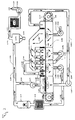
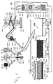
- a belt sintering plant essentially consists of a traveling grate 1.00, 2.00, 3.00, its upper run 1.01, 2.01, 3.01 and lower run 1.02, 2.02, 3.02 consists of individual grate cars 2.114, 3.114, 6.114, which are movably connected to each other to form a chain.
- Each grate car 2.114, 3.114, 6.114 has wheels 6.118, which a carriage floor are rotatably mounted on axles.
- This car floor is designed as a grate 6.117, the grate bars 6.102 Include spaces 6.103 between them.
- the grids 6,117 several grate cars 2.114, 3.114, 6.114 form the moving grate 1.00, 2.00, 3.00.
- the grate car 2.114, 3.114, 6.114 has below of its wagon floor carriers 6,119, on which the grate wagon 2,114, 3.114, 6.114 recorded and over the length of the traveling grate 1.00, 2.00, 3.00 is transported.
- the grate bars rise in the longitudinal direction above the floor of the car 6.102 extending side walls 6.115, 6.116, the rust Limit 6.117 on its side edges facing the wheels 6.118.
- On the grid 6.117 lies between the side walls 6.115, 6,116 a rust covering 1.63, 2.63, 3.63 and a sintered bed 1.62, 2.62, 3.62.
- the grate car 2.114, 3.114, 6.114 rolls on its wheels 6,118 on a not shown chassis of a sintering plant from a front deflection roller 1.03, 2.03, 3.03 in the feed direction 1.86, 2.86, 3.86 to a rear pulley 1.04, 2.04, 3.04, where it is either from the sub-run 1.02, 2.02, 3.02 to the upper run 1.01, 2.01 3.01 or from the upper run 1.01, 2.01, 3.01 is diverted to the subtrum 1.02, 2.02, 3.02.
- the surface of the upper run 1.01 is from the grate bars 6.102 of the grate car 6.114.
- This grate car 6,114 ends via a feed device 1.87 a collecting container 1.46, which has a Pelletizer 1.61 is connected to a mixer 1.42.
- Mixers 1.42 are mixing arms 1.39, 1.40, 1.41 on a rotatable Fixed shaft 1.43, driven by a 1.88 drive becomes.
- the drive 1.88 can be designed as an electric motor.
- Three feed pipes 1.36, 1.37, 1.38, from open into the mixer 1.42 each with a storage container 1.26, 1.28, 1.30 connected is. Through the inlet pipes 1.36, 1.37, 1.38 an in the contents of the storage containers 1.26, 1.28, 1.30 1.32, 1.33, 1.34 into the mixer 1.42.
- the content 1.32 consists of a residue 1.27, which has a Mill 1.35 and a sieve, not shown, which in the course of Inlet pipe 1.36 are arranged, passed into the mixer 1.42 becomes. Through the mill 1.35 and the sieve, the residue 1.27 becomes like this equalized that he introduced into the mixer 1.42 without lumps can be and in this way with the help of mixer 1.42 a consistent mixture can be made.
- the content 1.33 can be made of solid fuel, for example coke breeze 1.29 exist in a predetermined mixing ratio to Residual material 1.27 is introduced into mixer 1.42. If due the type of residue 1.27 a solid fuel is required is selected, the mixing ratio so that the of the Coke breeze 1.29 provided energy for one after ignition the sintering mixture, which runs independently, is sufficient, and around in a sintering zone forming in the sintering bed 1.62 1.64 the temperatures of 1300 ° C necessary for sintering Set +/- 100 ° C as soon as that which is put on the moving grate 1.00 Sinter bed 1.62 of pilot burners 1.51, 1.52 of a ignition hood 1.50 ignited with the help of pilot lights 1.53 on its surface has been.
- coke breeze 1.29 exist in a predetermined mixing ratio to Residual material 1.27 is introduced into mixer 1.42. If due the type of residue 1.27 a solid fuel is required is selected, the mixing ratio so that the of the Coke breeze 1.29 provided energy for one after ignition
- the coke breeze is 1.29 within the sinter mixture about evenly distributed.
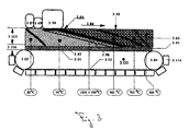
- a sintering zone 1.64 forms, which differs from one Upper run 1.01 facing away from the top 1.90 of the sintered bed 1.62 over a length of the traveling grate 1.00 required for sintering diagonally in the conveying direction of the sintered bed 1.62 to the surface of the upper strand 1.01.
- the content 1.34 of the storage container 1.30 consists of aggregates 1.31, for example from limestone, dolomite stone and / or Magnesium oxide. These additives 1.31 are used in the mixer 1.42 existing mixture 1.130 a desired chemical To give property, in particular a predetermined alkalinity.
- the one arranged between the mixer 1.42 and the feed device 1.87 Pelletizing system 1.61 is used to extract from the mixer 1.42 convert mixture emerging 1.130 into a granulate 1.44 before into the funnel 1.48 in the manner described below Grate car 6.114 arrives.
- the sinter mixture prepared in this way has the advantage that it is in a relatively loose bed Sinter bed 1.62 can form, so that even with moderate negative pressure of the induced draft fan 1.23 enough air through the on the grate 6.117 horizontal sinter bed 1.62 and the grate 1.63 sucked through can be a cheap sintering of the sintered bed To reach 1.62.
- the pelletizer 1.61 consists of a pelletizer 1.60, which with spray nozzles 1.58 and scrapers 1.59 as a cleaning device Is provided.
- the pelletizer 1.60 opens an inlet pipe 1.45, which is connected to the mixer 1.42 is.
- the pelletizer 1.60 opens Humidification tube 1.56, which is equipped on the one hand with the spray nozzles 1.58 and on the other hand connected to a reservoir 1.55 is.
- a metering valve 1.57 is arranged in the humidification tube 1.56. with the help of the inlet one in the reservoir 1.55 existing granulation liquid 1.54 can be dosed.
- the granulating liquid 1.54 is directed in the direction of the spray nozzles 1.58 atomized onto a good to be granulated and thus promotes the Granulation process.
- This pelletizer 1.60 can be made from one Granulation plate, a granulation cone or from a granulation tube consist. After a sufficient residence time of the mixture within the pelletizer 1.60 is the resultant Granulate 1.44 via a collecting container 1.46 to the feeder 1.87 passed.
- the feeder 1.87 is between the side walls 6.115, 6.116 of the grate wagon 6.114 and has two funnels 1.47, 1.48. These two funnels 1.47, 1.48 are in the longitudinal direction of the Moving grate 1.00 arranged in such a way that initially the somewhat narrower funnel 1.47 and only afterwards the somewhat wider funnel 1.48 into an under the funnels 1.47, 1.48 grate wagons 6.114, flow into it.
- the rolling rust car 6.114 merging narrow funnel 1.47 with a storage container 1.85 is connected via a drain pipe 1.89, the Grate covering 1.63 placed on grate 6.117.
- rolls the rust wagon 6.114 under the larger funnels 1.48 the one immediately or via the pelletizing system 1.61 with the mixer 1.42 connected is.
- the sintered bed is then via this funnel 1.47 1.62 on the grate covering already resting on the 6,117 grate 1.63 piled up.
- the one consisting of the two funnels 1.47, 7.47, 1.48, 7.48 Feeder has two functions. On the one hand, there must be medium-sized sintered pieces 1.71 as rust covering 1.63 in a layer thickness of approx. 3 up to 5 cm evenly on the surface facing the ignition hood 1.50 of the upper run 1.01 to the respective grate 6.117 Protect the grate car 6.114, 3.114 against excessive temperatures.
- the rust coating prevents the sinter mixture from passing through the the interstices 6.103 lying in the grate bars 6.102, sucked through becomes.
- the second task of the feeder 1.87 is in it, on the grate covering applied to the 6,117 grate 1.63 the mixture 1.130 optionally as granules 1.44 over the Collection container 1.46 as sinter bed 1.62 in a defined Apply layer height.
- the two funnels 1.47, 1.48 are each adjustable in distance to the surface of the upper run 1.01 attached between the side walls 6.115, 6.116 in order to by adjusting the respective funnel 1.47, 1.48 the Layer thickness of the grate 1.63 and / or the sintered bed 1.62 or the entire sintered bed 1.62 including the grate 1.63 to be able to vary.
- the shortening corresponds to one for the grate covering 1.63 defined thickness of the layer 3.106.
- the funnel 7.48 to give up the sintered bed 1.62 is at the same height as that front end wall 7.125 of the funnel 7.47 adjustable on the funnel 7.47 attached to ensure the exit of the rust coating 1.63 to be able to.
- the exhaust system 1.09 connects to the intake manifold 1.07 essentially from a suction nozzle 1.10, a condenser 1.11, a thermal afterburning 1.14 and a filter arrangement 1.18 exists.
- the suction pipe 1.07 is above the suction nozzle 1.10 in connection with the capacitor 1.11, through which one from the Sinter bed 1.62 exhaust 1.08 extracted with the help of the induced draft fan 1.23 is sucked through.
- the thermal afterburning 1.14 is connected downstream of the condenser 1.11, which burns such gas components from the exhaust gas 1.08, which could not be condensed in the condenser 1.11.
- the exhaust gases emerging from thermal afterburning 1.14 are in a downstream gas cooler 1.16, through which for example a cooling coil 1.17 can be cooled, before entering the filter assembly 1.18, the gas cooler 1.16 is connected downstream.
- This filter arrangement 1.18 can consist of an electrostatic filter 1.19 and an activated carbon filter 1.20, which are connected in series are. Instead of the activated carbon filter 1.20, a gas scrubber can also be used 1.21 or catalyst can be used. In the electrostatic filter 1.19 solid particles are extracted from the sintered bed 1.62 Exhaust gas 1.08 excreted.
- the activated carbon filter 1.20 or Gas scrubber 1.21 or catalytic converter takes other harmful Gas components, such as dioxins, on others Way can not be disposed of.
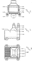
- the sinter pieces breaking off from the sinter bed 1.62, 9.66 fall into the crusher 1.66 and the fingers 9,126, 10,126 towards taken to the free spaces 10.128 of the crushing grate 9.129, 10.129.
- the sinter chunks are removed from fingers 9,126, 10.126 in the free spaces 10.128 of the crushing grate 9.129, 10.129 crushed and thereby into the width of the free spaces 10.128 defined size broken. Breaking the sinter bed 1.62 is favored by the fact that this in the area of the deflection roller 1.04 breaks off from moving grate 1.00.
- the sinter 1.65 After the sinter 1.65 has left the crusher 1.66, it becomes fed to a screening device 1.78 and classified. Thereby owns the screening device 1.78 receives the sintered pieces Sieve bottom 1.68, on which large sintered pieces 1.67 from the rest Sintered pieces separated and drained into a receptacle 1.73 become.
- the sieve tray 1.68 are further sieve trays 1.69, 1.70 downstream, which together with the sieve tray 1.68 the classifying Represent screening device 1.78.
- On the sieve bottom 1.68 downstream sieve tray 1.69 becomes medium-sized sintered pieces 1.71 sieved and introduced into a receptacle 1.77. These sintered pieces 1.71 are transported on a conveyor 1.79.
- This conveyor 1.79 is with its the receptacle 1.77 opposite end 1.80 facing a collection container 1.81, in the medium-sized sintered pieces transported on conveyor 1.79 1.71 can be filled. Between this collecting container 1.81 and a storage container 1.85, a further conveyor 1.84 is provided, the sintered pieces 1.71 from the collecting container 1.81 in the Storage container 1.85 promotes.
- This conveyor 1.84 can be considered a Vertical conveyor to be formed in the cross direction a conveyor tube 1.82 running conveyor stages 1.83 the sintered pieces 1.71 in the storage container 1.85.
- the sintered pieces 1.71 are made from the storage container 1.85 Rust coating on the grate bars 6.102 of the grate wagon 3.114, 6.114 upset.
- the feeder 1.87 with a Provide inlet 8.124 which is connected to the reservoir via a drain pipe 1.89 1.85 is connected.
- This inlet 8.124 is with a funnel extending over the width of the grating 6,117 1.47, 8.47 connected via which the sintered pieces 1.71 for protection the grate bars 6.102 against overheating over the entire width of the Grid 6,117 can be distributed.
- the thickness of the with the Sintered pieces 1.71 produced layer selected so that the grate bars 6.102 are reliably protected against overheating.
- These fine ingredients 1.75 improve under the air permeability behavior of the on the traveling grate 1.00 to be applied to be sintered mixture 1.130 and thus the Quality of the sinter.
- the small sintered pieces 1.72 are classified as sieves with a Grain size of approx. 3 to 10 mm as the product of the receptacle 1.73 fed. These sintered pieces 1.72 together with the coarse sintered pieces 1.67 represent the desired end product.
- the sintered pieces 1.71 serve with a grain size of approx. 10 to 20 mm the sintering process as a rust coating 1.63.
- All grain sizes over 20 mm can, depending on the further use purpose either further classified or completely a sinter cooler 1.74 are fed.
- the sintered pieces are in the sinter cooler 1.74 to a temperature that is favorable for further processing cooled down.
- the sinter 1.65 is already cooled in its upper part by the air flow.
- the one in Sinter cooler 1.74 cooled sinter is sent for final recycling, for example like a sintered iron ore with additives placed in a blast furnace or other plant that serves to smelt iron ore.
- the sinter 1.65 still share include, which are detrimental to pig iron extraction, for example Alloy components, so can the sinter 1.65 find use for other purposes, for example as a building material for the production of roads.
- the entire solid components of the Sinter mix are so firmly integrated in the sinter that they even under the influence of groundwater not from the sinter 1.65 can be washed out.
- thermocouples instead, which is 1.00 in along the entire length of the traveling grate the suction hoods 1.05 below the upper run 1.01 are and constantly the temperatures in the exhaust gases 1.08 measure up. According to these measurements, the through the sintered bed 1.62 air flow drawn through it, the thickness of the layer 3.105 of the sintered bed 1.62 and the feed speed of the traveling grate 1.00 regulated.
- a partial hood 2.269 is provided, in which the Partial stream 2,264 is collected after passing through the sinter bed 2.62 and the rust covering 2.63 has passed and the sintered bed 2.62 has dried.
- the partial flow emerges from the partial hood 2.269 2.264 via an outlet connection into a suction fan 2.271, that promotes this partial flow 2.264 into a manifold 2.272.
- a cyclone 2.273 is arranged in this collecting line 2.272, in which any solids that fail from that through the manifold 2,272 transported air stream 2,290 are also conveyed. These solids fall into a collection container in the Cyclone 2.273 2,274 from which it was taken and returned to the rest of the cycle can be.
- Cyclone 2.273 is a filter combination via a line 2.275 2.18, through which the funded by line 2.275 Airflow 2.277 sucked through by another blower 2.23 becomes.
- this filter combination 2.18 harmful Components filtered out of the air flow 2.277, so that the Blower 2.23 on one pressure side 2.24 cleaned exhaust air 2.25 emits that is environmentally friendly.
- Another partial flow 2,281 which is in the area of the cooling area 2.263 warmed while cooling the sintered bed 2.62, is in Direction to an ignition area 2.282 and a sintered area 2.283 of the traveling grate.
- An air flow 2,284 of the partial flow 2,281 contributes to the fact that the the mixture lying on the traveling grate the necessary for combustion Air is supplied.
- This airflow 2.284 is through the mixture 2.62 from in the area of the ignition range 2.282 a fan 2.285 sucked through, on its pressure side 2.286 via a pipeline 2.287 with a condenser 2.11 and a combustion chamber 2.14 is connected.
- Aerosols excreted in the exhaust gas and in the combustion chamber 2.14 become combustible and toxic components of an exhaust gas flow 2,296 burned, that from the ignition area 2.282 and the sintered area 2,283 can originate. This creates exhaust gases 2,290 which the manifold 2.272 in the cyclone 2.273 and the filter combination 2,276 can be derived.
- an airflow 2.291 becomes the one Part of the partial flow 2.281 is sucked through by a fan 2.292.
- This also creates a flow of 2,293 flammable exhaust gases, which have a temperature corresponding to the sintering temperature.
- the fan presses this current 2,293 through a pipe 2.294 in one above the ignition range 2.282 in the Ignition hood 2.50 arranged burner 2.51, its pilot lights 2.53 towards the sinter bed 2.62 lying on the traveling grate emerge. These pilot lights 2.53 ignite the sintered bed 2.62.
- the Airflow 2.293 is used to supply the burner 2.51. Contained in it combustible exhaust gas components can be burned in burner 2.51 become.
- the hot combustion gases generated during combustion 2.296 are from the fan 2.285 via the pipeline 2.287 and the condenser 2.11 to the combustion chamber 2.14.
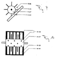
- a stationary grate 4.99 Find use. Basically, the sintering process proceeds the stationary grate 4.99 in a similar way as on the traveling grate 1.00. For this purpose it is above the stationary grate 4.99 a mixer 4.42 is provided which is connected to storage containers 4.26, 4.28, 4.30 is filled. These storage containers 4.26, 4.28, 4.30 contain the products to be mixed in mixer 4.42, namely Residues, solid fuel and aggregates. These are about the feed pipes 4.36, 4.37, 4.38 entered into the mixer 4.42.
- the mixed product 4.130 enters from the mixer 4.42 Connection tube 4.45 into a funnel 4.92 if a corresponding one Slider 4.97 is opened, the connecting tube 4.45 sealed against the stationary grate 4.99.
- the funnel 4.92 is connected to the stationary grate via a pivotable tube 4.93 4.99 connected.
- the pivotable tube 4.93 enables one even filling of the stationary grate 4.99.
- Another connecting pipe opens into the funnel 4.92 4.89, the hopper 4.92 with the reservoir 4.85 connects.
- Inside the connecting pipe 4.89 is a slide 4.96 provided, with the help of the outlet of rust 4.63 can be controlled from the storage container 4.85.
- the slide 4.96 is opened. Now the rust covering 4.63 can be opened using the pivotable tube 4.93 the grate floor 4.104 can be distributed.
- This grate floor contains 4.104 a layer thickness 4.106 of about 3 to 5 cm around the grate bars 4.102 to protect and prevent thermal destruction that the sinter mixture from the vacuum of the induced draft fan 4.23 is sucked through the grate floor 4.104.
- a layer thickness of 4.105 is generated, which can correspond to the height of the pan wall.
- the connecting pipe 4.45 closed with the slider 4.97.
- the ignition hood 4.50 in the direction of the Sintered bed 4.62 arranged from the pilot lights 4.53 in the direction emerge on the sintered bed 4.62 and this on its surface ignite. It is below the stationary grate 4.99 in the Suction hood 4.05 generates a vacuum sufficient to withstand the sintering zone 4.64 generated by pilot lights 4.53 through the sintering bed 4.62 to suck through. In this way, the entire sintered bed 4.62 sintered.
- the sintering zone 4.64 runs with the stationary grate 4.99 parallel to the grate floor 4.104. This process also proceeds a sintered front in the suction direction parallel to the sintering zone 4.64 4.98.
- the resulting exhaust gases 4.08 are generated by the induced draft fan 4.23 sucked off through the suction pipe 4.07.
- the exhaust gases occur 4.08 through the condenser 4.11 and the thermal afterburning 4.14 in the electrostatic filter 4.19 and the activated carbon filter 4.20 gas scrubber 4.21 or catalyst.
- the remaining exhaust gas leaves on the pressure side 4.24 of the induced draft fan 4.23 as cleaned exhaust gas 4.25 the facility.
- stationary Grids 5.107, 5.108, 5.109 operated in a common system.
- a first stationary grate 5.109 is placed over the swiveling one Pipe 5.93 covered with the rust covering 5.63 and the sintered bed 5.62.
- a funnel 5.92 is expediently available for this purpose, the one over the pivotable pipe 5.93 with the grates 5.107, 5.108, 5.109 can be connected.
- the slide 5.96 is closed and the slide 5.97 open. Now emerges through the connecting pipe 5.45 Mixer 5.42 the mixture to be sintered 5.130 through the connecting pipe 5.45 towards the funnel 5.92 from which it is over the pivotable tube 5.93 is directed to the grate 5.109 and itself deposited on layer 5.106. After the sintered bed 5.62 one the correct layer for sintering has reached 5.105, the slide is 5.97 closed.
- the ignition hood 5.50 along the Rail 5.113 in the direction of the first stationary grate 5.109 process the sintered bed that has been fully formed on this grate 5.109 5.62 to ignite. For this purpose it will open through of valve 5.112 the suction hood 5.05 of the first stationary grate 5.109 to the vacuum generated by the induced draft fan 5.23 connected.
- the ignition hood 5.50 along the rail 5.113 to the now filled one move the third stationary grate 5.108, so that this on this trained sintered bed 5.62 can be ignited.
- the valve 5.111 is opened so that the suction fan 5.23, induced draft produced the exhaust gases 5.08 through the sintered bed 5.62 can suck through.
- the sintering bed 5.62 sinters on the first stationary one Grate 5.109 up to the surface of grate bars 5.102 when open Valve 5.112.
- the pivotable tube 5.93 is in the direction of the second stationary grate 5.107 pivoted so that this when closed Valve 5.110 again filled with a sintered bed 5.62 can be.
- the resulting sinter 1.65, 3.65, 4.65, 5.65 generally has an iron content of 40 to 65%, preferably 50 to 60% of the total weight. In addition, it has a content of 3 to 20%, preferably 5 to 10% of SiO 2 and an Al 2 O 3 content of 1 to 10%, preferably 1 to 5% of its total weight.
- the sintered 1.65, 3.65, 4.65, 5.65 has a base degree in the ratio CaO to SiO 2 of 0.8 to 3, preferably 1 to 2. Its MgO content is between 0 to 3%, preferably 1 to 2% of the total weight.
Landscapes
- Engineering & Computer Science (AREA)
- Mechanical Engineering (AREA)
- General Engineering & Computer Science (AREA)
- Environmental & Geological Engineering (AREA)
- Chemical & Material Sciences (AREA)
- Manufacturing & Machinery (AREA)
- Geochemistry & Mineralogy (AREA)
- Geology (AREA)
- General Life Sciences & Earth Sciences (AREA)
- Life Sciences & Earth Sciences (AREA)
- Materials Engineering (AREA)
- Metallurgy (AREA)
- Organic Chemistry (AREA)
- Manufacture And Refinement Of Metals (AREA)
- Processing Of Solid Wastes (AREA)
- Treatment Of Sludge (AREA)
- Processing And Handling Of Plastics And Other Materials For Molding In General (AREA)
Claims (24)
- Procédé de valorisation de résidus (1.27 ; 4.27 ; 5.27) à faible taille de particules, contenant des résidus organiques et des composants minéraux, dans lequel les résidus sont frittés sur un lit de frittage (1.62 ; 2.62 ; 3.62 ; 4.62 ; 5.62), les résidus organiques étant éliminés sous forme de gaz d'échappement (1.08 ; 4.08 ; 5.08) du lit de frittage (1.62 ; 2.62 ; 3.62 ; 4.62 ; 5.62) auquel est appliquée une pression réduite, et le produit fritté formé (1.65 ; 3.65 ; 4.65 ; 5.65) et le gaz d'échappement (1.08 ; 4.08 ; 5.08) étant envoyés séparément vers une application de valorisation appropriée, caractérisé par le fait que les résidus sont constitués d'une boue de ponçage contenant du huile et du fer et que la procédé comprend le frittage d'un mélange de fer et de composants minéraux contenu dans la boue de ponçage.
- Procédé selon la revendication 1, caractérisé par le fait que l'on mélange le résidu (1.27, 4.27, 5.27) dans un mélangeur (1.42, 4.42, 5.42) avec des additifs (1.31, 4.31, 5.31) et que l'on soumet l'ensemble à un frittage.
- Procédé selon la revendication 1 ou 2, caractérisé par le fait que l'on ajoute au résidu (1.27, 4.27, 5.27), en fonction de sa teneur en composants combustibles, un combustible solide (1.29, 4.29, 5.29).
- Procédé selon la revendication 3, caractérisé par le fait que l'énergie fournie par la combustion des composants combustibles du résidu (1.27, 4.27, 5.27) est suffisante, et qu'il n'est de ce fait pas nécessaire d'ajouter du combustible solide (1.29, 4.29, 5.29).
- Procédé selon l'une des revendications 1 à 4, caractérisé par le fait que l'on ajoute au résidu (1.27, 4.27, 5.27) et au combustible solide (1.29, 4.29, 5.29) des additifs (1.31, 4.31, 5.31) et que l'on prépare à partir de ces trois composants un mélange (1.130,4.130,5.130) à partir duquel on fabrique un produit fritté (1.65, 3.65, 4.65, 5.65) ayant la qualité recherchée.
- Procédé selon la revendication 5, caractérisé par le fait que l'on ajoute en tant qu'additif (1.31, 4.31, 5.31) de fines particules (1.75, 4.75, 5.75) obtenues par tamisage après frittage du produit fritté (1.65, 3.65, 4.65, 5.65).
- Procédé selon l'une quelconque des revendications 1 à 6, caractérisé par le fait que le mélange (1.130, 4.130, 5.130) est déposé sur une grille (1.00, 2.00, 3.00, 4.105, 5.104) sous forme d'un lit de frittage (1.62, 2.62, 3.62, 4.62, 5.62) ayant une épaisseur régulière (3.105).
- Procédé selon la revendication 7, caractérisé par le fait que l'épaisseur du lit de frittage (1.00, 2.00, 3.00) dépend du rapport de mélange des composants dans le mélange (1.130, 4.130, 5.130).
- Procédé selon l'une quelconque des revendications 1 à 8, caractérisé par le fait qu'il comprend une étape de frittage dans une zone de frittage (1.64, 3.64, 4.64) et que des résidus organiques sont séparés en tant que composant du gaz d'échappement (1.08, 4.08, 5.08), dans un front de frittage (3.98, 4.98, 5.98) qui évolue, devant la zone de frittage (1.64, 3.64, 4.64, 5.64) dans le sens des gaz d'échappement (1.08, 4.08, 5.08) aspirés à travers le lit de frittage (1.62, 2.62, 3.62, 4.62, 5.62).
- Procédé selon la revendication 8 et/ou 9, caractérisé par le fait que le lit de frittage (1.62, 2.62, 3.62) est déposé sous forme d'une couche (3.105) sur une grille mobile (1.00, 2.00, 3.00), laquelle épaisseur dépend de la vitesse d'avancement de la grille mobile (1.00, 2.00, 3.00) et de la pression réduite à laquelle est soumis le lit de frittage (1.00, 2.00, 3.00) pour l'obtention d'un produit fritté (1.65, 3.65) ayant les propriétés recherchées.
- Procédé selon l'une quelconque des revendications 8 à 10, caractérisé par le fait que la vitesse d'avancement de la grille mobile (1.00, 2.00, 3.00) est régulée de manière à ce qu'à son extrémité (1.91) le lit de frittage (1.62, 2.62, 3.62) soit fritté sur toute l'épaisseur allant de sa surface supérieure (1.90) jusqu'au revêtement de grille (1.63, 2.63, 7.63), et que tous les résidus organiques soient éliminés du lit de frittage (1.62, 2.62, 3.62).
- Procédé selon la revendication 11, caractérisé par le fait que des morceaux frittés (1.71, 4.71, 5.71) de taille moyenne ayant une dimension maximale d'environ 10 à 20 mm sont recyclés vers la grille (1.00, 2.00, 3.00, 4.99, 5.107, 5.108, 5.109) en tant que revêtement de grille (1.63, 2.63, 7.63), les barreaux de la grille (4.102, 5.102, 6.102) étant protégées par le revêtement de grille (1.63, 2.63, 3.63, 4.63, 5.63) contre un chauffage excessif.
- Procédé selon l'une quelconque des revendications 1 à 12, caractérisé par le fait que l'on mesure dans la zone des hottes d'aspiration (1.05) la température des gaz d'échappement (1.08, 4.08, 5.08) sortant du lit de frittage (1.62, 2.62, 3.62, 4.62, 5.62) et que l'on déduit des températures mesurées ainsi les températures à l'intérieur du lit de frittage (1.62, 2.62, 3.62, 4.62, 5.62).
- Procédé selon l'une quelconque des revendications 8 à 13, caractérisé par le fait que la vitesse d'avancement de la grille mobile (1.00, 2.00, 3.00) et la pression réduite appliquée au niveau du brin supérieur (1.01, 2.01, 3.01) de celle-ci sont réglés en fonction de la température à l'intérieur du lit de frittage (1.62, 2.62, 3.62, 4.62, 5.62).
- Procédé selon l'une quelconque des revendications 8 à 13, caractérisé par le fait que la vitesse d'avancement et la pression réduite appliquée sont réglées en fonction de la température dans la zone de frittage (1.64, 3.64).
- Procédé selon l'une quelconque des revendications 1 à 9, 12 et/ou 13, caractérisé par le fait que l'on applique un revêtement de grille (4.63, 5.63) et, sur celui-ci, un lit de frittage (4.62, 5.62) sur un plancher de grille (4.104, 5.104) d'une grille stationnaire (4.99, 5.99), que l'on allume l'ensemble à l'aide d'une hotte d'allumage (4.50, 5.50) au niveau de sa surface supérieure (1.90) et que le frittage se fait en direction du plancher de grille (4.104, 5.104), la zone de frittage (4.64, 5.64) étant soumise à une aspiration parallèle au plan de la surface du plancher de grille (4.104, 5.104) et à travers le lit de frittage (4.62, 5.62).
- Procédé selon l'une quelconque des revendications 1 à 16, caractérisé par le fait que l'on ajuste la température dans une zone de frittage (1.64, 3.64, 4.64, 5.64) en fonction du matériau à traiter à une valeur variable de 1300 °C ± 500 °C.
- Procédé selon l'une quelconque des revendications 1 à 17, caractérisé par le fait que des morceaux frittés (1.67, 1.72, 4.67, 4.72, 5.67, 5.72) séparés par tamisage sont utilisés, en fonction de leur composition, pour la fabrication de fer.
- Procédé selon l'une quelconque des revendications 1 à 17, caractérisé par le fait que des morceaux frittés (1.67, 1.72, 4.67, 4.72, 5.67, 5.72) sont utilisés, en fonction de leur composition, en tant que matériau pour la construction.
- Procédé selon l'une quelconque des revendications 1 à 19, caractérisé par le fait que les gaz d'échappement (1.08, 4.08, 5.08) formés lors du frittage sont envoyésvers une installation de traitement de gaz d'échappement (1.09, 4.09, 5.09).
- Procédé selon la revendication 20, caractérisé par le fait que le gaz d'échappement (1.08, 4.08, 5.08) est au moins partiellement condensé et que le condensat obtenu est au moins partiellement brûlé.
- Procédé selon la revendication 20 et/ou 21, caractérisé par le fait que les gaz d'échappement (1.08, 4.08, 5.08) sont épurés par postcombustion thermique.
- Procédé selon l'une quelconque des revendications 20 à 22, caractérisé par le fait qu'un gaz d'échappement soumis à une postcombustion thermique (1.14, 2.14, 4.14, 5.14) est traité, pour que l'on puisse le rejeter, dans un dispositif approprié permettant de séparer des composés chlorés.
- Procédé selon l'une quelconque des revendications 1 à 23, caractérisé par le fait que le mélange (1.130, 4.130, 5.130) est soumis à une granulation avant d'être déposé sur la grille (1.00, 2.00, 3.00, 4.99, 5.99) afin d'optimiser sa perméabilité à l'air et d'améliorer la qualité du produit fritté (1.65, 4.65, 5.65).
Applications Claiming Priority (2)
| Application Number | Priority Date | Filing Date | Title |
|---|---|---|---|
| DE4414321 | 1994-04-25 | ||
| DE4414321A DE4414321A1 (de) | 1994-04-25 | 1994-04-25 | Verfahren und Anlage zur Verwertung von mit organischen Rückständen versetzten Reststoffen sowie Sinter |
Publications (3)
| Publication Number | Publication Date |
|---|---|
| EP0679726A2 EP0679726A2 (fr) | 1995-11-02 |
| EP0679726A3 EP0679726A3 (fr) | 1996-12-18 |
| EP0679726B1 true EP0679726B1 (fr) | 2001-11-28 |
Family
ID=6516331
Family Applications (1)
| Application Number | Title | Priority Date | Filing Date |
|---|---|---|---|
| EP95106033A Expired - Lifetime EP0679726B1 (fr) | 1994-04-25 | 1995-04-21 | Procédé de valorisation de déchets contaminés par des polluants organiques |
Country Status (3)
| Country | Link |
|---|---|
| EP (1) | EP0679726B1 (fr) |
| AT (1) | ATE209702T1 (fr) |
| DE (2) | DE4414321A1 (fr) |
Families Citing this family (5)
| Publication number | Priority date | Publication date | Assignee | Title |
|---|---|---|---|---|
| AT405530B (de) * | 1996-07-11 | 1999-09-27 | Voest Alpine Ind Anlagen | Verfahren zur thermischen behandlung von organisch belasteten materialien |
| HUP0600317A2 (en) | 2006-04-24 | 2008-08-28 | Bem Zrt | Recicling and transformation of hazardous wastes and of metals, metal oxides at industrial starting material |
| DE102013010885A1 (de) * | 2013-07-01 | 2015-01-22 | Eisenmann Ag | Verfahren zum Sintern von Sinterwerkstücken sowie Anlage hierfür |
| DE102017103432A1 (de) | 2017-02-20 | 2018-08-23 | Outotec (Finland) Oy | Verfahren zur thermischen Behandlung von Schüttgut mit mechanischer Trennvorrichtung |
| LU100260B1 (en) * | 2017-05-22 | 2019-01-04 | Wurth Paul Sa | Method of operating a sinter plant |
Family Cites Families (7)
| Publication number | Priority date | Publication date | Assignee | Title |
|---|---|---|---|---|
| US3909189A (en) * | 1971-08-25 | 1975-09-30 | Mcdowell Wellman Eng Co | Process for conditioning sinter draft for electrostatic precipitation of particulate material therefrom |
| DE3231384A1 (de) * | 1982-08-24 | 1984-03-01 | Metallgesellschaft Ag, 6000 Frankfurt | Verfahren zum sintern von sintermischungen auf einem wanderrost |
| DE3534139A1 (de) * | 1985-09-25 | 1987-04-02 | Metallgesellschaft Ag | Verfahren zur agglomeration von mineralischen schlaemmen |
| DE3602562A1 (de) * | 1986-01-29 | 1987-07-30 | Metallgesellschaft Ag | Verfahren zur herstellung von festen agglomeraten aus mineralischen schlaemmen |
| DE3642172A1 (de) * | 1986-12-10 | 1988-06-16 | Metallgesellschaft Ag | Verfahren zur herstellung von festen agglomeraten aus stichfesten mineralischen schlaemmen |
| DE3809358A1 (de) * | 1988-03-19 | 1989-09-28 | Metallgesellschaft Ag | Verfahren zur herstellung von festen agglomeraten aus mineralischen schlaemmen |
| DE4109396C2 (de) * | 1991-03-22 | 1994-08-11 | Fachbetrieb Metallischer U Cer | Verfahren zum Herstellen von Eisenerz-Pellets |
-
1994
- 1994-04-25 DE DE4414321A patent/DE4414321A1/de not_active Withdrawn
-
1995
- 1995-04-21 EP EP95106033A patent/EP0679726B1/fr not_active Expired - Lifetime
- 1995-04-21 AT AT95106033T patent/ATE209702T1/de not_active IP Right Cessation
- 1995-04-21 DE DE59509875T patent/DE59509875D1/de not_active Expired - Fee Related
Non-Patent Citations (1)
| Title |
|---|
| Ludwig von Bogdandy und Hans-Jürgen Engell, "Die Reduktion der Eisenerze",1967, Springer-Verlag Berlin, S. 347,350-352 * |
Also Published As
| Publication number | Publication date |
|---|---|
| DE4414321A1 (de) | 1995-10-26 |
| EP0679726A2 (fr) | 1995-11-02 |
| DE59509875D1 (de) | 2002-01-10 |
| EP0679726A3 (fr) | 1996-12-18 |
| ATE209702T1 (de) | 2001-12-15 |
Similar Documents
| Publication | Publication Date | Title |
|---|---|---|
| DE69123609T2 (de) | Verfahren und Vorrichtung zur Wiederverwertung anorganischer Verbindungen | |
| DE1809874C3 (fr) | ||
| DE2321194A1 (de) | Verfahren und vorrichtung zur beseitigung von fluessigkeiten in einem fliessbettreaktor | |
| DE3636479A1 (de) | Verfahren und anordnung zur thermo-mechanischen regenerierung von schuettguetern, insbesondere von giesserei-altsand | |
| DE4109136A1 (de) | Verfahren und vorrichtung zum aufbereiten schadstoffbelasteter abfallstoffe | |
| EP0437679A1 (fr) | ProcÀ©dé pour le traitement des résidus d'incinérateurs des déchets et incinérateurs pour la mise en oeuvre du procédé | |
| EP1007746A1 (fr) | Procede permettant de faire fonctionner une installation de frittage, et installation de frittage | |
| DE2621220A1 (de) | Verfahren zur behandlung von materialien und ofensystem zur waermebehandlung von materialien | |
| DE3520819C2 (de) | Verfahren zur thermischen Behandlung von mit Schadstoffen belasteten Massen sowie Anlage zur Durchführung eines solchen Verfahrens | |
| EP0679726B1 (fr) | Procédé de valorisation de déchets contaminés par des polluants organiques | |
| DE1919137A1 (de) | Verfahren und Vorrichtung zum Erhitzen von brennbare Fremdstoffe mitfuehrendem Gut und Verbrennen der Fremdstoffe | |
| DD141056A5 (de) | Verfahren und vorrichtung zur aufbereitung und verbrennung von kohle | |
| EP0413799B1 (fr) | Arrangement des grilles d'incineration de dechets et de detritus ainsi que methode d'operation | |
| AT505227A1 (de) | Verfahren zur herstellung von formlingen | |
| DE1608023B1 (de) | Ofen mit bewegtem Einsatz zur thermischen Behandlung von grobkoernigem Gut | |
| EP0571722B1 (fr) | Procédé et schéma d'installation pour sécher et brûler des matières résiduaires | |
| DE2950259A1 (de) | Verfahren und anlage zur verwendung der in einer erzsinteranlage angesaugten gase | |
| WO2021074057A1 (fr) | Dispositif de refroidissement et procédé permettant de refroidir un matériau en vrac | |
| DE69429017T2 (de) | Anlage zur erzeugung von asche enthaltenden produkten und energie aus abfällen | |
| DE3315557A1 (de) | Verfahren und einrichtung zum reinigen feinstueckigen gutes von oeligen oder fettigen verunreinigungen, insbesondere zum reinigen mit schneidoel verunreinigter metallspaene | |
| BE1027673B1 (de) | Kühler und Verfahren zum Kühlen von Schüttgut | |
| EP1507877B1 (fr) | Procede de frittage de matieres contenant de l'oxyde de fer sur une machine de frittage | |
| DE1299792B (de) | Vorrichtung zum Verbrennen fester Abfallstoffe | |
| DE1608023C (de) | Ofen mit bewegtem Einsatz zur ther mischen Behandlung von grobkörnigem Gut | |
| DE29704859U1 (de) | Apparat für kontinuierlich oder diskontinuierlich ablaufende Stoff- und/oder Wärmeübergangsprozesse |
Legal Events
| Date | Code | Title | Description |
|---|---|---|---|
| PUAI | Public reference made under article 153(3) epc to a published international application that has entered the european phase |
Free format text: ORIGINAL CODE: 0009012 |
|
| AK | Designated contracting states |
Kind code of ref document: A2 Designated state(s): AT BE CH DE DK ES FR GB GR IE IT LI LU MC NL PT SE |
|
| RHK1 | Main classification (correction) |
Ipc: C22B 1/20 |
|
| PUAL | Search report despatched |
Free format text: ORIGINAL CODE: 0009013 |
|
| AK | Designated contracting states |
Kind code of ref document: A3 Designated state(s): AT BE CH DE DK ES FR GB GR IE IT LI LU MC NL PT SE |
|
| 17P | Request for examination filed |
Effective date: 19970618 |
|
| 17Q | First examination report despatched |
Effective date: 19981005 |
|
| GRAG | Despatch of communication of intention to grant |
Free format text: ORIGINAL CODE: EPIDOS AGRA |
|
| RTI1 | Title (correction) |
Free format text: PROCESS FOR VALORISATION OF WASTE, CONTAMINATED WITH ORGANIC SUBSTANCES |
|
| GRAG | Despatch of communication of intention to grant |
Free format text: ORIGINAL CODE: EPIDOS AGRA |
|
| GRAH | Despatch of communication of intention to grant a patent |
Free format text: ORIGINAL CODE: EPIDOS IGRA |
|
| GRAH | Despatch of communication of intention to grant a patent |
Free format text: ORIGINAL CODE: EPIDOS IGRA |
|
| GRAA | (expected) grant |
Free format text: ORIGINAL CODE: 0009210 |
|
| AK | Designated contracting states |
Kind code of ref document: B1 Designated state(s): AT BE CH DE DK ES FR GB GR IE IT LI LU MC NL PT SE |
|
| PG25 | Lapsed in a contracting state [announced via postgrant information from national office to epo] |
Ref country code: NL Free format text: LAPSE BECAUSE OF FAILURE TO SUBMIT A TRANSLATION OF THE DESCRIPTION OR TO PAY THE FEE WITHIN THE PRESCRIBED TIME-LIMIT Effective date: 20011128 Ref country code: IT Free format text: LAPSE BECAUSE OF FAILURE TO SUBMIT A TRANSLATION OF THE DESCRIPTION OR TO PAY THE FEE WITHIN THE PRE;WARNING: LAPSES OF ITALIAN PATENTS WITH EFFECTIVE DATE BEFORE 2007 MAY HAVE OCCURRED AT ANY TIME BEFORE 2007. THE CORRECT EFFECTIVE DATE MAY BE DIFFERENT FROM THE ONE RECORDED.SCRIBED TIME-LIMIT Effective date: 20011128 Ref country code: IE Free format text: LAPSE BECAUSE OF FAILURE TO SUBMIT A TRANSLATION OF THE DESCRIPTION OR TO PAY THE FEE WITHIN THE PRESCRIBED TIME-LIMIT Effective date: 20011128 Ref country code: GR Free format text: LAPSE BECAUSE OF FAILURE TO SUBMIT A TRANSLATION OF THE DESCRIPTION OR TO PAY THE FEE WITHIN THE PRESCRIBED TIME-LIMIT Effective date: 20011128 Ref country code: GB Free format text: LAPSE BECAUSE OF FAILURE TO SUBMIT A TRANSLATION OF THE DESCRIPTION OR TO PAY THE FEE WITHIN THE PRESCRIBED TIME-LIMIT Effective date: 20011128 Ref country code: FR Free format text: LAPSE BECAUSE OF FAILURE TO SUBMIT A TRANSLATION OF THE DESCRIPTION OR TO PAY THE FEE WITHIN THE PRESCRIBED TIME-LIMIT Effective date: 20011128 |
|
| REF | Corresponds to: |
Ref document number: 209702 Country of ref document: AT Date of ref document: 20011215 Kind code of ref document: T |
|
| REG | Reference to a national code |
Ref country code: CH Ref legal event code: EP |
|
| REG | Reference to a national code |
Ref country code: IE Ref legal event code: FG4D Free format text: GERMAN |
|
| REG | Reference to a national code |
Ref country code: GB Ref legal event code: IF02 |
|
| REF | Corresponds to: |
Ref document number: 59509875 Country of ref document: DE Date of ref document: 20020110 |
|
| PG25 | Lapsed in a contracting state [announced via postgrant information from national office to epo] |
Ref country code: SE Free format text: LAPSE BECAUSE OF FAILURE TO SUBMIT A TRANSLATION OF THE DESCRIPTION OR TO PAY THE FEE WITHIN THE PRESCRIBED TIME-LIMIT Effective date: 20020228 Ref country code: PT Free format text: LAPSE BECAUSE OF FAILURE TO SUBMIT A TRANSLATION OF THE DESCRIPTION OR TO PAY THE FEE WITHIN THE PRESCRIBED TIME-LIMIT Effective date: 20020228 Ref country code: DK Free format text: LAPSE BECAUSE OF FAILURE TO SUBMIT A TRANSLATION OF THE DESCRIPTION OR TO PAY THE FEE WITHIN THE PRESCRIBED TIME-LIMIT Effective date: 20020228 |
|
| PG25 | Lapsed in a contracting state [announced via postgrant information from national office to epo] |
Ref country code: MC Free format text: LAPSE BECAUSE OF NON-PAYMENT OF DUE FEES Effective date: 20020421 Ref country code: LU Free format text: LAPSE BECAUSE OF NON-PAYMENT OF DUE FEES Effective date: 20020421 Ref country code: AT Free format text: LAPSE BECAUSE OF NON-PAYMENT OF DUE FEES Effective date: 20020421 |
|
| PG25 | Lapsed in a contracting state [announced via postgrant information from national office to epo] |
Ref country code: LI Free format text: LAPSE BECAUSE OF NON-PAYMENT OF DUE FEES Effective date: 20020430 Ref country code: CH Free format text: LAPSE BECAUSE OF NON-PAYMENT OF DUE FEES Effective date: 20020430 Ref country code: BE Free format text: LAPSE BECAUSE OF NON-PAYMENT OF DUE FEES Effective date: 20020430 |
|
| NLV1 | Nl: lapsed or annulled due to failure to fulfill the requirements of art. 29p and 29m of the patents act | ||
| GBV | Gb: ep patent (uk) treated as always having been void in accordance with gb section 77(7)/1977 [no translation filed] |
Effective date: 20011128 |
|
| PG25 | Lapsed in a contracting state [announced via postgrant information from national office to epo] |
Ref country code: ES Free format text: LAPSE BECAUSE OF FAILURE TO SUBMIT A TRANSLATION OF THE DESCRIPTION OR TO PAY THE FEE WITHIN THE PRESCRIBED TIME-LIMIT Effective date: 20020530 |
|
| REG | Reference to a national code |
Ref country code: IE Ref legal event code: FD4D |
|
| EN | Fr: translation not filed | ||
| PLBE | No opposition filed within time limit |
Free format text: ORIGINAL CODE: 0009261 |
|
| STAA | Information on the status of an ep patent application or granted ep patent |
Free format text: STATUS: NO OPPOSITION FILED WITHIN TIME LIMIT |
|
| PG25 | Lapsed in a contracting state [announced via postgrant information from national office to epo] |
Ref country code: DE Free format text: LAPSE BECAUSE OF NON-PAYMENT OF DUE FEES Effective date: 20021101 |
|
| 26N | No opposition filed | ||
| REG | Reference to a national code |
Ref country code: CH Ref legal event code: PL |