EP0679018B1 - Verfahren und Vorrichtung zur seitlichen Registrierkontrolle beim Drucken von Farben - Google Patents
Verfahren und Vorrichtung zur seitlichen Registrierkontrolle beim Drucken von Farben Download PDFInfo
- Publication number
- EP0679018B1 EP0679018B1 EP95302514A EP95302514A EP0679018B1 EP 0679018 B1 EP0679018 B1 EP 0679018B1 EP 95302514 A EP95302514 A EP 95302514A EP 95302514 A EP95302514 A EP 95302514A EP 0679018 B1 EP0679018 B1 EP 0679018B1
- Authority
- EP
- European Patent Office
- Prior art keywords
- belt
- lateral position
- adjusting
- profile data
- transverse
- Prior art date
- Legal status (The legal status is an assumption and is not a legal conclusion. Google has not performed a legal analysis and makes no representation as to the accuracy of the status listed.)
- Expired - Lifetime
Links
Images


Classifications
-
- G—PHYSICS
- G03—PHOTOGRAPHY; CINEMATOGRAPHY; ANALOGOUS TECHNIQUES USING WAVES OTHER THAN OPTICAL WAVES; ELECTROGRAPHY; HOLOGRAPHY
- G03G—ELECTROGRAPHY; ELECTROPHOTOGRAPHY; MAGNETOGRAPHY
- G03G15/00—Apparatus for electrographic processes using a charge pattern
- G03G15/75—Details relating to xerographic drum, band or plate, e.g. replacing, testing
- G03G15/754—Details relating to xerographic drum, band or plate, e.g. replacing, testing relating to band, e.g. tensioning
- G03G15/755—Details relating to xerographic drum, band or plate, e.g. replacing, testing relating to band, e.g. tensioning for maintaining the lateral alignment of the band
-
- B—PERFORMING OPERATIONS; TRANSPORTING
- B41—PRINTING; LINING MACHINES; TYPEWRITERS; STAMPS
- B41J—TYPEWRITERS; SELECTIVE PRINTING MECHANISMS, i.e. MECHANISMS PRINTING OTHERWISE THAN FROM A FORME; CORRECTION OF TYPOGRAPHICAL ERRORS
- B41J13/00—Devices or arrangements of selective printing mechanisms, e.g. ink-jet printers or thermal printers, specially adapted for supporting or handling copy material in short lengths, e.g. sheets
- B41J13/26—Registering devices
-
- G—PHYSICS
- G06—COMPUTING; CALCULATING OR COUNTING
- G06K—GRAPHICAL DATA READING; PRESENTATION OF DATA; RECORD CARRIERS; HANDLING RECORD CARRIERS
- G06K15/00—Arrangements for producing a permanent visual presentation of the output data, e.g. computer output printers
- G06K15/02—Arrangements for producing a permanent visual presentation of the output data, e.g. computer output printers using printers
- G06K15/12—Arrangements for producing a permanent visual presentation of the output data, e.g. computer output printers using printers by photographic printing, e.g. by laser printers
- G06K15/129—Colour printing
-
- H—ELECTRICITY
- H04—ELECTRIC COMMUNICATION TECHNIQUE
- H04N—PICTORIAL COMMUNICATION, e.g. TELEVISION
- H04N1/00—Scanning, transmission or reproduction of documents or the like, e.g. facsimile transmission; Details thereof
- H04N1/04—Scanning arrangements, i.e. arrangements for the displacement of active reading or reproducing elements relative to the original or reproducing medium, or vice versa
- H04N1/047—Detection, control or error compensation of scanning velocity or position
- H04N1/053—Detection, control or error compensation of scanning velocity or position in main scanning direction, e.g. synchronisation of line start or picture elements in a line
-
- H—ELECTRICITY
- H04—ELECTRIC COMMUNICATION TECHNIQUE
- H04N—PICTORIAL COMMUNICATION, e.g. TELEVISION
- H04N1/00—Scanning, transmission or reproduction of documents or the like, e.g. facsimile transmission; Details thereof
- H04N1/46—Colour picture communication systems
- H04N1/50—Picture reproducers
- H04N1/506—Reproducing the colour component signals picture-sequentially, e.g. with reproducing heads spaced apart from one another in the subscanning direction
-
- G—PHYSICS
- G03—PHOTOGRAPHY; CINEMATOGRAPHY; ANALOGOUS TECHNIQUES USING WAVES OTHER THAN OPTICAL WAVES; ELECTROGRAPHY; HOLOGRAPHY
- G03G—ELECTROGRAPHY; ELECTROPHOTOGRAPHY; MAGNETOGRAPHY
- G03G2215/00—Apparatus for electrophotographic processes
- G03G2215/00135—Handling of parts of the apparatus
- G03G2215/00139—Belt
- G03G2215/00143—Meandering prevention
- G03G2215/00156—Meandering prevention by controlling drive mechanism
-
- G—PHYSICS
- G03—PHOTOGRAPHY; CINEMATOGRAPHY; ANALOGOUS TECHNIQUES USING WAVES OTHER THAN OPTICAL WAVES; ELECTROGRAPHY; HOLOGRAPHY
- G03G—ELECTROGRAPHY; ELECTROPHOTOGRAPHY; MAGNETOGRAPHY
- G03G2215/00—Apparatus for electrophotographic processes
- G03G2215/00135—Handling of parts of the apparatus
- G03G2215/00139—Belt
- G03G2215/00143—Meandering prevention
- G03G2215/0016—Meandering prevention by mark detection, e.g. optical
-
- G—PHYSICS
- G03—PHOTOGRAPHY; CINEMATOGRAPHY; ANALOGOUS TECHNIQUES USING WAVES OTHER THAN OPTICAL WAVES; ELECTROGRAPHY; HOLOGRAPHY
- G03G—ELECTROGRAPHY; ELECTROPHOTOGRAPHY; MAGNETOGRAPHY
- G03G2215/00—Apparatus for electrophotographic processes
- G03G2215/00135—Handling of parts of the apparatus
- G03G2215/00139—Belt
- G03G2215/00143—Meandering prevention
- G03G2215/00164—Meandering prevention by electronic scan control
-
- G—PHYSICS
- G03—PHOTOGRAPHY; CINEMATOGRAPHY; ANALOGOUS TECHNIQUES USING WAVES OTHER THAN OPTICAL WAVES; ELECTROGRAPHY; HOLOGRAPHY
- G03G—ELECTROGRAPHY; ELECTROPHOTOGRAPHY; MAGNETOGRAPHY
- G03G2215/00—Apparatus for electrophotographic processes
- G03G2215/01—Apparatus for electrophotographic processes for producing multicoloured copies
- G03G2215/0167—Apparatus for electrophotographic processes for producing multicoloured copies single electrographic recording member
- G03G2215/0174—Apparatus for electrophotographic processes for producing multicoloured copies single electrographic recording member plural rotations of recording member to produce multicoloured copy
-
- H—ELECTRICITY
- H04—ELECTRIC COMMUNICATION TECHNIQUE
- H04N—PICTORIAL COMMUNICATION, e.g. TELEVISION
- H04N1/00—Scanning, transmission or reproduction of documents or the like, e.g. facsimile transmission; Details thereof
- H04N1/04—Scanning arrangements, i.e. arrangements for the displacement of active reading or reproducing elements relative to the original or reproducing medium, or vice versa
- H04N1/113—Scanning arrangements, i.e. arrangements for the displacement of active reading or reproducing elements relative to the original or reproducing medium, or vice versa using oscillating or rotating mirrors
- H04N1/1135—Scanning arrangements, i.e. arrangements for the displacement of active reading or reproducing elements relative to the original or reproducing medium, or vice versa using oscillating or rotating mirrors for the main-scan only
-
- H—ELECTRICITY
- H04—ELECTRIC COMMUNICATION TECHNIQUE
- H04N—PICTORIAL COMMUNICATION, e.g. TELEVISION
- H04N1/00—Scanning, transmission or reproduction of documents or the like, e.g. facsimile transmission; Details thereof
- H04N1/04—Scanning arrangements, i.e. arrangements for the displacement of active reading or reproducing elements relative to the original or reproducing medium, or vice versa
- H04N1/12—Scanning arrangements, i.e. arrangements for the displacement of active reading or reproducing elements relative to the original or reproducing medium, or vice versa using the sheet-feed movement or the medium-advance or the drum-rotation movement as the slow scanning component, e.g. arrangements for the main-scanning
-
- H—ELECTRICITY
- H04—ELECTRIC COMMUNICATION TECHNIQUE
- H04N—PICTORIAL COMMUNICATION, e.g. TELEVISION
- H04N2201/00—Indexing scheme relating to scanning, transmission or reproduction of documents or the like, and to details thereof
- H04N2201/024—Indexing scheme relating to scanning, transmission or reproduction of documents or the like, and to details thereof deleted
- H04N2201/02406—Arrangements for positioning elements within a head
- H04N2201/02439—Positioning method
-
- H—ELECTRICITY
- H04—ELECTRIC COMMUNICATION TECHNIQUE
- H04N—PICTORIAL COMMUNICATION, e.g. TELEVISION
- H04N2201/00—Indexing scheme relating to scanning, transmission or reproduction of documents or the like, and to details thereof
- H04N2201/04—Scanning arrangements
- H04N2201/047—Detection, control or error compensation of scanning velocity or position
- H04N2201/04701—Detection of scanning velocity or position
- H04N2201/0471—Detection of scanning velocity or position using dedicated detectors
-
- H—ELECTRICITY
- H04—ELECTRIC COMMUNICATION TECHNIQUE
- H04N—PICTORIAL COMMUNICATION, e.g. TELEVISION
- H04N2201/00—Indexing scheme relating to scanning, transmission or reproduction of documents or the like, and to details thereof
- H04N2201/04—Scanning arrangements
- H04N2201/047—Detection, control or error compensation of scanning velocity or position
- H04N2201/04701—Detection of scanning velocity or position
- H04N2201/04732—Detecting at infrequent intervals, e.g. once or twice per line for main-scan control
-
- H—ELECTRICITY
- H04—ELECTRIC COMMUNICATION TECHNIQUE
- H04N—PICTORIAL COMMUNICATION, e.g. TELEVISION
- H04N2201/00—Indexing scheme relating to scanning, transmission or reproduction of documents or the like, and to details thereof
- H04N2201/04—Scanning arrangements
- H04N2201/047—Detection, control or error compensation of scanning velocity or position
- H04N2201/04701—Detection of scanning velocity or position
- H04N2201/04741—Detection of scanning velocity or position by detecting the sheet support or the photoconductive surface directly
-
- H—ELECTRICITY
- H04—ELECTRIC COMMUNICATION TECHNIQUE
- H04N—PICTORIAL COMMUNICATION, e.g. TELEVISION
- H04N2201/00—Indexing scheme relating to scanning, transmission or reproduction of documents or the like, and to details thereof
- H04N2201/04—Scanning arrangements
- H04N2201/047—Detection, control or error compensation of scanning velocity or position
- H04N2201/04753—Control or error compensation of scanning position or velocity
- H04N2201/04755—Control or error compensation of scanning position or velocity by controlling the position or movement of a scanning element or carriage, e.g. of a polygonal mirror, of a drive motor
-
- H—ELECTRICITY
- H04—ELECTRIC COMMUNICATION TECHNIQUE
- H04N—PICTORIAL COMMUNICATION, e.g. TELEVISION
- H04N2201/00—Indexing scheme relating to scanning, transmission or reproduction of documents or the like, and to details thereof
- H04N2201/04—Scanning arrangements
- H04N2201/047—Detection, control or error compensation of scanning velocity or position
- H04N2201/04753—Control or error compensation of scanning position or velocity
- H04N2201/04756—Control or error compensation of scanning position or velocity by controlling the position or movement of the sheet, the sheet support or the photoconductive surface
-
- H—ELECTRICITY
- H04—ELECTRIC COMMUNICATION TECHNIQUE
- H04N—PICTORIAL COMMUNICATION, e.g. TELEVISION
- H04N2201/00—Indexing scheme relating to scanning, transmission or reproduction of documents or the like, and to details thereof
- H04N2201/04—Scanning arrangements
- H04N2201/047—Detection, control or error compensation of scanning velocity or position
- H04N2201/04753—Control or error compensation of scanning position or velocity
- H04N2201/04758—Control or error compensation of scanning position or velocity by controlling the position of the scanned image area
- H04N2201/04767—Control or error compensation of scanning position or velocity by controlling the position of the scanned image area by controlling the timing of the signals, e.g. by controlling the frequency o phase of the pixel clock
- H04N2201/04781—Controlling the phase of the signals
- H04N2201/04786—Controlling a start time, e.g. for output of a line of data
-
- H—ELECTRICITY
- H04—ELECTRIC COMMUNICATION TECHNIQUE
- H04N—PICTORIAL COMMUNICATION, e.g. TELEVISION
- H04N2201/00—Indexing scheme relating to scanning, transmission or reproduction of documents or the like, and to details thereof
- H04N2201/04—Scanning arrangements
- H04N2201/047—Detection, control or error compensation of scanning velocity or position
- H04N2201/04753—Control or error compensation of scanning position or velocity
- H04N2201/04758—Control or error compensation of scanning position or velocity by controlling the position of the scanned image area
- H04N2201/04787—Control or error compensation of scanning position or velocity by controlling the position of the scanned image area by changing or controlling the addresses or values of pixels, e.g. in an array, in a memory, by interpolation
-
- H—ELECTRICITY
- H04—ELECTRIC COMMUNICATION TECHNIQUE
- H04N—PICTORIAL COMMUNICATION, e.g. TELEVISION
- H04N2201/00—Indexing scheme relating to scanning, transmission or reproduction of documents or the like, and to details thereof
- H04N2201/04—Scanning arrangements
- H04N2201/047—Detection, control or error compensation of scanning velocity or position
- H04N2201/04753—Control or error compensation of scanning position or velocity
- H04N2201/04794—Varying the control or compensation during the scan, e.g. using continuous feedback or from line to line
Definitions
- the present invention relates to methods and apparatus for controlling the position of a longitudinally moving belt and, more particularly, to such methods and apparatus by which the belt may be controlled with high precision.
- the present invention also relates to methods and apparatus for controlling lateral image registration on a longitudinally moving belt.
- each image area on a photoconductive belt must make at least four passes relative to a transverse line scan by a modulated laser beam or a linear array of light emitting diodes and registered to within a maximum of a 0.1 millimeter circle or within a tolerance of ⁇ 0.05 mm.
- Source imaging methods require specifications that could be four (4) times as stringent, i.e., a 0.025 mm circle or ⁇ 0.0125 mm tolerance.
- the use of timing marks spaced longitudinally on the belt in correspondence with the image areas, coupled with available electronic sensors and associated circuitry has enabled longitudinal registration of the image areas, or registration in the direction of belt travel, acceptably within this degree of precision.
- a diagonal line sensor has recently been applied to belt tracking control called “phase plane control", using a similar mechanism.
- Belt position is proportionally measured once per revolution, and the additional information thus available from the diagonal line sensor enables improved corrective action.
- Steering commands are deduced from the combination of position, ita rate of change, and the number of iterations according to a specialized set of control rules.
- This system has a position measuring range of 14 mm peak-to-peak, but the displacement rate is maintained low enough to achieved an error of 0.3 mm over consecutive color separations.
- US-A-4,557,372 discloses an alignment apparatus for a belt system which is representative of belt control schemes that rely on independent measurements of two or more target patterns on the belt. In these types of systems, lateral displacement of each individual target is sensed and a displacement signal input to a belt steering device.
- the major difficulty with this type of belt alignment control is that the accuracy of alignment is dictated by the accuracy of the individual targets on the belt. In order to achieve target precision within ⁇ 0.1 mm, the costs of manufacturing the belt and providing the targets becomes excessive.
- EP 0494105 A2 proposes a method and apparatus for transverse registration of image exposures on photoconductive belts subject to lateral deviation from linear travel in which targets, corresponding in location to the image areas to be exposed, are used for the detection of lateral belt displacement and to control the transverse location of exposure scans.
- the targets are of a pattern defining a reference line and a line inclined with respect to the direction of belt travel so that the duration of time between passage of the target lines with respect to a spacially fixed sensing axis will vary with lateral displacement of the belt.
- the targets may assume a variety of specific patterns and the teachings of that patent are applicable to single and multi-pass image exposure systems as well as to both modulated laser and light emitting diode types of raster output scanners or other exposure devices.
- a major disadvantage of the above belt tracking control mechanisms, methods and algorithms is that they are not accurate enough to maintain the lateral belt position to within the range of about ⁇ 0.1mm.
- An object of the invention is to provide such a method and apparatus for assuring transverse registration of successive image exposures on such belts.
- a further object of the invention is the provision of an improved method and apparatus for detecting lateral displacement of a longitudinally moving belt at spaced increments of the belt length.
- a still further object of the invention is to provide a method and apparatus for detecting the lateral position of a photoconductive belt in relation to an image area during a first and successive multiple exposures by a transverse scanning device and adjusting the effective scan location of that device so that the first and each successive image are in precise registration with each other.
- Yet another object of the invention is the provision of such a method and apparatus which is adaptable to and includes diverse types of such transverse scanning devices and scanning procedures.
- Another object of the present invention is to provide a method and apparatus for maintaining an endless photoconductor belt to within lateral position variations smaller than the manufacturing tolerances allowed in forming the belt.
- Still yet another object of the invention is to provide an alignment control method and apparatus for endless photoconductive belts by which the lateral position of such belt can be maintained within a 0.1 mm circle.
- the present invention contemplates new and improved methods and apparatus for lateral registration control of a moving belt which overcome the above-referenced problems and provide sufficient accuracy for such applications as color printing.
- an apparatus and method for controlling the transverse registration of an image area to be exposed on a longitudinally moving continuous belt subject to lateral deviation from linear travel.
- an apparatus and method for controlling the lateral position of the longitudinally moving endless belt subject to lateral deviation from linear travel.
- the method for controlling the transverse registration of an image area to be exposed on a longitudinally moving belt includes steps of providing belt edge profile data, detecting a lateral position of the belt during movement of the belt by measuring the lateral position of the belt edge, and adjusting the relative traverse locations of the image and the belt to compensate for a difference between the detected lateral belt edge position and the belt edge profile data, the belt edge profile data being provided as moving average belt edge profile data, comprising an average lateral position of the belt edge at given longitudinal positions along the belt with respect to a spatially fixed reference point taken over a predetermined plurality of belt cycles.
- the apparatus for controlling the traverse registration of an image area to be exposed on a longitudinally moving belt includes a processing unit for providing the belt edge profile data, an edge position detector for detecting a lateral position of the belt during movement of the belt by measuring the lateral position of the belt edge at one of a plurality of longitudinal positions along the belt, and an output scanner control means for adjusting the transverse location of the image area on the belt to compensate for a difference between the detected lateral position of the belt edge and the moving average of the belt edge profile data related to that longitudinal position.
- the method of controlling the lateral position of a longitudinally moving endless belt includes the steps of providing moving average belt edge profile data, detecting a lateral position of the belt during movement of the belt by measuring the lateral position of the belt edge at a longitudinal position along the belt, generating a steering command signal by calculating a difference between the detected lateral position of the belt edge and the moving average belt edge profile data corresponding to that longitudinal position, and adjusting the lateral position of the belt by steering the belt in response to the steering command.
- the method preferably further comprises the step of determining when said longitudinally moving belt reaches a quasi steady state in said lateral deviation from linear travel by: calculating moving average belt profile data relating i) each of said plurality of longitudinal positions along said belt passing adjacent said spatially fixed reference point for a predetermined plurality of belt cycles to ii) an average lateral position of said belt edge at each of said plurality of longitudinal positons along said belt with respect to said reference point for said predetermined number of belt cycles; detecting a first lateral position data set of said belt during movement of the belt by measuring the lateral position of said belt edge at said plurality of longitudinal positions along said belt; calculating a plurality of difference data values by comparing said moving average belt edge profile data with said first lateral position data set for each of said plurality of longitudinal positions along said belt; and, realizing said quasi steady state when each of said plurality of difference data values are within a predetermined value range.
- the apparatus for controlling the lateral position of the longitudinally moving endless belt includes a processing unit storing the moving average belt edge profile data, an edge position detector for detecting a lateral position of the belt during movement thereof by measuring the lateral position of the belt edge at one of a plurality of longitudinal positions along the belt, a lateral registration controller for generating a steering command signal by calculating a difference between the detected lateral position of the belt edge and the moving average belt edge profile data corresponding to the one longitudinal position, and a guide roller for steering the belt in response to said steering command signal.
- transverse registration of an image area to be exposed on a longitudinally moving photoconductor belt which is subject to lateral deviation from linear travel is achieved by detecting the lateral position of the belt, and adjusting the transverse location of the image area on the belt to compensate for the distance between the detected lateral position of the belt and a previously stored historical moving average belt edge position signature information.
- the lateral position of the belt for each of the multiple exposures is detected and the scanning device is adjusted for each of the succeeding presentations as needed to account for deviation of the transverse position of the belt during each succeeding exposure.
- the invention comprises a method for controlling a lateral position of a longitudinally moving endless belt by measuring belt edge displacement from a spatially fixed reference point a plurality of times during each revolution of belt movement to provide a set of data relating the belt edge position with a plurality of longitudinal positions along the belt. For each longitudinal position, a current value of measured displacement is obtained whereupon the current value of measured displacement and at least one prior value of measured displacement is averaged to provide a current moving average value of measured displacement. A difference between the instantaneous belt edge position and the current moving average value of measured displacement is calculated to provide a belt steering correction command signal for each longitudinal position along the belt. The belt is steered in accordance with the belt steering signal as necessary to reduce the current average value of measured displacement as close to zero as possible.
- the invention may be embodied in a multi-pass belt exposure system in which a given image area is presented successively to a single scanning device by multiple belt revolutions or in a single pass system in which an image area is presented successively to a plurality of longitudinal spaced scanning devices.
- the invention is adapted for use with laser and light emitting diode types of traverse scanning device or raster output scanners as disclosed in EP 0494105 A2.
- the scanner employs a modulated laser beam to define a transverse line of scan
- lateral shifting of the image exposure in response to the difference between the detected lateral position of the belt and the previously stored moving average edge position signature information, is effected electronically by starting and ending the active or modulated segment of each line scan at points corresponding to the detected difference.
- a raster output scanner such as a linear array of light emitting diodes
- a combination of electronically displacing the line of scan and physical shifting of the diode array is used.
- a course image shift is effected by electronically shifting between the respective LEDs to start and end the transverse scan line in a manner similar to that described with respect to a laser.
- Fine shifting of the LED array is effected by physical shifting of the array rack using a electro-mechanical device such as a piezoelectric stack, or other forms of linear electronically controlled drive devices well known in the art such as motor activated servo systems.
- a primary advantage of the present invention is the provision of an improved method for attaining transverse registration of an image exposure on a longitudinally traveling photoconductive belt by which the problems associated with lateral deviation from linear travel of such belts are substantially overcome.
- Another advantage of the present invention is the provision of a highly effective apparatus for implementing such a method.
- Fig. 1 of the drawings The typical lateral deviation of a standard photoconductive belt of the type discussed above is illustrated in Fig. 1 of the drawings. More precisely with regard to Fig. 1, gross lateral fluctuations of the belt itself are inferred from the position of the belt edge, which position is detected by an electro-optical or electro-mechanical sensor as the belt advances therepast. Since the belt under consideration here is continuous, each of the curves A, B and C represents the lateral belt edge position detected by a stationary fixed edge sensor as the belt traverses a single complete course therepast. The lateral belt edge position detected by the edge sensor is plotted on the ordinate and the position along the continuous length of the belt in units of revolutions is plotted on the abscissa.
- each of the curves A, B and C would overlay one another and the end of each curve as illustrated in the chart would blend smoothly with its beginning. However, this is not the case. Indeed, as can be seen in Fig. 1, although there is no scale of the ordinate, from each belt cycle to the next, the difference between the detected lateral position, or fluctuation, may well exceed the registration requirements mandated for color printing.
- the curves also indicate that the difference in belt registration are both frameto-frame and intraframe assuming a multipass system and a large enough image area on the length of the belt.
- the curves A, B and C represent typical lateral belt edge positions detected for a moving belt controlled by a prior art registration controller effecting a steering control of the belt.
- the lateral deviation within belt cycles is unacceptable.
- the present invention obtains an average belt edge position curve D which represents a moving average of the belt edge position curves of a most recent plurality of prior belt revolutions. Using this average curve, or ideal edge profile, average belt misregistration is reduced in a manner described in greater detail immediately below.
- the control senses a timing mark on the belt passing under a belt edge sensing device.
- the timing mark is preferably a laterally extending seam in the belt but may also be any other suitable indicia printed or otherwise placed on the belt surface in a manner so as to cooperate with the sensor.
- the edge sensor is preferably an electronic sensing array which generates an electrical signal indication of the belt edge position with respect to a spatially fixed reference point.
- a plurality of lateral belt edge positions are detected along equally spaced apart increments of longitudinal belt length.
- Each of the edge positions are associated with their respective longitudinal positions along the belt and stored in a memory. That is, as the belt advances a predetermined distance, e.g. two (2) inches (50mm) in the preferred embodiment, the edge sensor reads a position of the belt and pair-wise stores that edge position associated with the corresponding longitudinal position along the belt circumference.
- the edge sensor reads a position of the belt at regular intervals of time and length such as by detecting the angular displacement of a drive or guide roller. This procedure produces an edge profile data set or edge signature defined by the accumulated edge profile data with respect to a position mark along the belt. In the preferred embodiment, forty (40) values are recorded for an eighty (80) inch (200cm) belt.
- the above-discussed quasi-steady state control is achieved using gross tracking control according to prior art methods and apparatus.
- the gross tracking control brings the belt into this quasi-steady state by continuously relaxing the speed and magnitude of the control interventions until all of the lateral belt deviations detected are below a threshold value.
- the belt edge position is detected using a fine sensing array.
- the granularity of the fine sensing array for use with the instant invention is substantially less than that used for the prior art gross tracking control.
- the fine sensing array reads the edge positions in regular intervals of every two (2) inches (50mm) along the belt circumference. These measurements are averaged 18 for each longitudinal belt position by the controller of the present invention over a selected number of belt revolutions or periods such as from five (5) to ten (10) or so belt revolutions in the preferred embodiment. A least square procedure is applied to the accumulated data to determine the variance thereof. For each belt revolution, a new set of belt edge positions is accumulated and included with the earlier averaged data.
- the belt position variance eventually stabilizes at a low level when the quasi-steady state is reached as indicated above. It has been found that although long term drift occurs, short term drift such as between successive images in a multi-pass system has little effect on the image formed thereon.
- the control is satisfied that the belt has reached the quasi-steady state and begins to execute belt position and/or image registration control.
- the edge sensor reads a position of the belt edge at regular intervals of time and length along the belt, such as at every two (2) inches (50mm) along the belt circumference, and derives a value at each position which may be different from the previously accumulated average belt edge position.
- the most-recently-obtained belt edge position is added to the accumulated average position data and averaged therewith to effect a moving average.
- the most recently accumulated belt edge position is compared against the moving average to obtain a difference signal.
- this difference signal is applied to an image registration apparatus or a belt steering apparatus to effect a correction tending to urge either the belt itself or the image registered thereon back toward the accumulated moving average.
- the control system produces a corrective action to restore the system to the historical moving average.
- the edge position fluctuations appear to be random, correcting the belt position or raster output scanner position relative to the ideal edge profile does not guarantee that any single fluctuation of the registration is completely eliminated.
- the ideal edge profile computed by the control system according to the present invention is the average and therefore the most probable edge position, the control interventions reduce the average misregistration. According to the present invention, beneficial effects are realized, such as, for example, the frequency of the most objectionable fluctuations i.e. those exceeding 0.050 mm, are significantly reduced.
- the correction factor applied at step 22 may be utilized by either a tracking correction control such as a belt steering apparatus, a repositioning of a ROS bar or a timing change in a modulated laser imaging device.
- a tracking correction control such as a belt steering apparatus, a repositioning of a ROS bar or a timing change in a modulated laser imaging device.
- the apparatus for executing the correction according to the present invention includes a laterally moving raster output scanner ROS which restores the successive images applied to the multi-pass photoconductive belt passing thereunder.
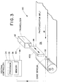
- FIG. 3 A schematic perspective view illustrating a system incorporating a first embodiment of the present invention is shown in Fig. 3.
- the system illustrated provides multiple exposures on a photoconductive belt by multiple passes of image areas on the belt in relation to a single laterally displaceable LED-type raster output scanner ROS.
- the image registration control system 30 includes a belt edge position sensor 32 which is electrically connected to a central controller 34.
- the central controller includes a processor 36 for calculating an average belt position profile as described above.
- a memory 38 is included within the central controller 34 for storing the moving average edge position data and other data necessary to effect the control.
- the central controller 34 performs an analysis of the most recently obtained belt edge position data with respect to a previously stored moving average data profile stored in the memory 38.
- An error correction signal is obtained based upon a difference between the detected position and the average position, which signal 40 is applied to a transducer 42.
- the transducer 42 reacts to the error correction signal 40 in a manner which compensates for the difference between the detected edge position and the average edge position to move or otherwise laterally displace the raster output scanner ROS 44.
- signals indicating instantaneous deviation of belt travel from the quasi-steady state average position developed by the central controller 34 are used to determine the precise traverse location of the first and subsequent successive image exposures in relation to the photoconductive belt 24. Also, precise intra-image registration is possible through proper selection of the longitudinal granularity of the data set.
- the image registration control system 30 illustrated in Fig. 3 responds to the difference between the detected instantaneous belt edge position and the average position at regular intervals of time and length as described above.
- the error correction signal 40 is applied to the transducer for every two (2) inches of belt travel. According to this information, for a typical eighty (80) inch photoconductive belt, the ROS 44 is repositioned continuously so as to smoothly correct the error at forty (40) longitudinal positions of the belt.
- the detected instantaneous belt edge position is "re-factored" into the running or moving average simultaneous with the repositioning of the raster output scanner 44.
- image registration control is provided both intra- and inter- image.
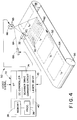
- FIG. 4 of the drawings another embodiment of the present invention is illustrated in a multi-pass xerographic printing system depicted schematically and designated generally be reference number 50.
- the system 50 includes a photoconductive belt trained about guide rollers 56 and 58, at least one of which is driven to advance the belt 54 in a longitudinal direction of processing travel depicted by the arrow 52.
- the length of belt 54 is designed to accept an integral number of spaced image areas I 1 - I n represented by dashed line rectangles in Fig. 4.
- each of the image areas I 1 - I n reaches a transverse line of scan, represented by a dashed arrow 60, it is progressively exposed on closely spaced transverse raster lines 62 shown with exaggerated longitudinal spacing on the image area I 1 in Fig. 4.
- the line 60 is scanned by a raster output scanner so that a modulated laser beam 64 is reflected to the line 60 by successive facets 65 on a rotatable polygon-shaped mirror 66.
- the beam 64 is emitted by a laser device 68 such as a laser diode, operated by a laser drive module 70 forming part of a control processor generally designated by reference numeral 72.
- the processor 72 includes a memory and other circuit or logic modules indicated by legends in Fig. 4 and includes a scanner drive command circuit 74 by which operation of a motor (not shown) for rotating the polygon mirror 66 is controlled.
- the processor is suitably connected to the belt edge position sensor 32.
- the processor 72 responds to a video signal to expose each raster line 62 to a linear segment to the video signal must be exposed in the same manner to four successive exposures, one for each of the three basic colors and black.
- a multi-pass system such as the system 50, where one raster output scanner or head is used, complete exposure of each color image area requires four revolutions of the belt 54.
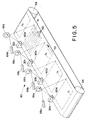
- a single pass system 80 is depicted in which each of several image areas I 1 - I 4 , precise spacing of the raster output scanners in this fashion is not critical. Because of the need for charging and developing the image exposed by each raster output scanner, however, a substantially spacing between the scanners in the longitudinal direction of the belt is required.
- a comparison of the multi-pass system of Fig. 4 with the single pass system of Fig. 5 will reveal that there is little difference in the manner by which each image area is successively subjected to multiple image exposures.
- the image areas I 1 - I n are successively exposed on successive raster lines 62 as each raster line registers with a transverse scan line 60 as a result of longitudinal movement of the belt 54.
- the belt of Fig. 4 could be shortened to the length needed to accommodate one or two image areas so that the distance of belt travel between successive scans approaches that of the belt in the single pass system.
- the length of the transverse scan line 60 or transverse scan lines 60a-60d, in the respective systems 50 and 80 is longer than the transverse dimension of the image areas I.
- Scan line length in this respect, is determined by the output scanner geometry and exceeds the length of the raster 62.
- the length of each raster line is determined by the time during which the laser diode is active to reflect a modulated beam from each facet 65 on the rotating polygon 66 as determined by the laser drive module 70 (not shown in FIG. 5).
- each transverse scan line is shifted in a transverse direction by control of the laser drive module 70 according to the error correction signal derived as indicated above and the transverse position of the exposed raster lines 62, and image areas I 1 - I n shifted in relation to the belts in the respective systems 50 and 80.
- signals indicating instantaneous deviation of belt travel from the quasi-steady state average position are developed and used to determine the precise transverse location of the first and successive image exposures in relation to the photoconductive belt 54 and to adjust the active portion of the transverse scan line 60 for each succeeding image as needed to assure precise longitudinal alignment or transverse registration of the succeeding images with the first image irrespective of the lateral position of the belt during exposure of the images.
- This operation is achieved in the illustrated embodiments and in substantial measure by the provision of a single belt edge sensor 32 or a plurality of sensors 32a-32d for sensing the belt edge and for generating signals used to obtain average belt edge signature data for comparison against actual instantaneous belt edge signals for real time on-the-fly control.
- Figs 4 and 5 of the drawings the general organization and flight path configuration of the photoconductor belt 54 was shown.
- the belt 54 is guided about fixed guide rollers, one or more of which may be driven to advance the belt 54 in the direction of the arrow 52.
- a belt steering roller 56 may be located at one end of the endless belt loop, that is, the left end as illustrated in Figs 4 and 5, a belt steering roller 56 may be located.
- the steering roller is thus located so that the portion of the belt wrapped on the roller separates opposed major flights or runs in belt 54.
- the steering roller 56 is located upstream from the edge sensor 32 in terms of the direction of belt travel.
- FIG. 6 an overall belt steering system embodiment of the invention is schematically illustrated in a functional block diagram.
- the photoconductor belt 54 is shown in a developed view, as if it were cut at the loop seam and stretched flat. Also such equivalent components previously described with reference to Figs 3-5, including the central controller 84 and a transducer 92 are schematically represented.
- the belt is shown with a single representative sensor or scanner 32 to provide a signal corresponding to lateral belt position for steering the belt in a manner which will be described in more detail with reference to Figs. 7-9.
- the steering roller 56 is supported for rotation on an axis 91 by a yoke 92 which, in turn, is carried at the end of a shaft 94 supported for rotation on a central longitudinal axis 96 which extends substantially parallel to the direction of belt travel.
- the shaft 94 is supported for both rotational and longitudinal movement in a bearing assembly 98 supported by a transverse beam 100 extending between opposite side walls 101 and 102.
- the side walls 101 and 102 and the beam 100 form part of the support structure for the belt 54.
- Such support structure is only partially illustrated in the drawings but further includes a transverse beam 104 spaced from the beam 100.
- the beam 104 supports a crank mechanism 106 which cooperates with a compression spring 108 to control the longitudinal position of the steering guide roller 56 on the axis 96.
- control of the angular position of the steering roller 56 about the axis 96 is effected by a stepping motor 110 fixed to the side wall 100 and having a final output shaft 112 connected to a cam 114 (Fig. 9).
- the stepping motor may include reduction gearing in advance of the output shaft 112.
- the cam 114 in the illustrated embodiment, underlies a follower plate 116 secured to an end of the yoke 92.
- a compression spring 118 biases the follower plate 116 into engagement with the cam 114 at all times.
- the system broadly represented in Fig. 6 includes the steering control apparatus illustrated in Figs 7-9 and also includes a gross tracking control processor 120, a gross belt edge sensor 122 and a gross belt tracking control actuator connected to the steering roller 56. All of the gross steering or belt tracking apparatus 120, 122 and 124 provide for the control of the belt to within the quasi-steady state parameters discussed above. Fine lateral registration control over the belt according to a belt steering embodiment of the invention includes a digital controller 84 which is provided with signal averaging, compensator and motor control modules. The stepper motor 110 is operated by a power drive controlled by the motor control module 92 of the digital controller 84.
- the invention is embodied in system 130 shown to include an LED raster output scanner 132 positioned above a photoconductive belt 54.
- the scanner 132 includes an LED array 134 and a selfoc lens group 136 by which image light is transmitted from the LED array 134 to a transverse scan line 20 on the belt 54.
- the LED array is supported at opposite ends by piezoelectric stacks 140 and 142 which extend to fixed supports 144.
- the system 130 further includes a control processor 146 having a control module 150, a course shift logic module 152 and a fine shift logic module 154.
- the course shift logic module has an input to an LED array control unit 156 by which image information is supplied to the LED array 134.
- a belt edge lateral registration error processor 160 receives error correction signal information originating within central controller 32 developed as described above with respect to FIGURES 2-5 of the drawings. As depicted in Fig. 10, the belt lateral registration error signal information 40 is supplied to the control module of the control processor 146.
- Figs 11 and 12 of the drawings The manner in which the system 130 is operated to shift the active line scan of the raster output scanner 132 in response to belt lateral position error may be understood by reference to Figs 11 and 12 of the drawings.
- the length of the scanner 132 exceeds the length of the image transverse scan line 20 so that the exposure of any given raster line on the photoconductive belt 54 will entail exposure illumination by less than the total number of LEDs in the array 134.
- This characteristic is represented in Fig. 11 by a transverse line of pixels in which exposed pixels are represented by white circles P a whereas inactive or non-exposed pixels are represented by black circles P i .
- the diameter of each pixel is represented in Fig. 11 by the dimension D p .
- the image transverse scan line 20 may be shifted to the right or to the left in increments corresponding to the pixel diameter D p .
- This operation may be effected by operation of the LED array control 156 and in accordance with the present invention is so controlled by the course shift logic module of the processor 146 in response to an image registration error signal representing a required shift or that magnitude.
- a further or fine shifting of the transverse location of the image line of scan 20 may be effected by physically shifting the raster output scanner 132.
- a shift of this nature is represented in Fig. 12 by the dimension S f and in practice need not be any greater than the radius of the LED pixels or one half the dimension D p .
- Such fine shifting is effected by operation of the piezoelectric stacks 140 and 142 under the control of the fine shift logic module 154 of the processor 146.
- a piezoelectric "inch worm” drive in which linear motion is achieved by successive clamping, extending and unclamping of three separate driving piezoelectric cylinders about a drive cylindrical shaft connected to the scanner 132, may be used.
- a single piezoelectric stack such as 140 can be used while the opposite end of raster output scanner 132 is simply guided and free to move laterally.
- the photoconductor belt edge sensors may be combined into a single device and suitably shared between the gross tracking control and the registration control in a time division fashion.
Claims (10)
- Ein Verfahren zur Querausrichtung eines Bildbereiches (In), der auf einem sich in Längsrichtung bewegenden Band (54) belichtet werden soll, das Gegenstand einer seitlichen Abweichung von der geradlinigen Bewegung ist, das die Schritte umfaßt, Profildaten des Bandrandes bereitzustellen, die sich auf die seitliche Position des Bandrandes in bezug auf einen räumlich festgelegten Bezugspunkt an einer Längsposition entlang des sich bewegenden Bandes beziehen, eine seitliche Position des Bandes während der Bewegung zu erfassen, indem die seitliche Position des Bandes an der einen Längsposition entlang des Bandes gemessen und diese mit den Profildaten des Bandrandes verglichen wird, und die relative Querlage des Bildbereiches und des Bandes einzustellen, um irgendeine Differenz zwischen der erfaßten seitlichen Position des Bandrandes und den Profildaten des Bandrandes auszugleichen, die sich auf die eine Längsposition beziehen, gekennzeichnet durchden Schritt, als die genannten Profildaten des Bandrandes sich bewegende mittlere Profildaten des Bandrandes bereitzustellen, die eine mittlere seitliche Position des genannten Bandrandes an der einen Längsposition entlang des genannten Bandes in bezug auf den genannten räumlich festgelegten Bezugspunkt während einer vorbestimmten Mehrzahl von Bandzyklen umfassen.
- Ein Verfahren gemäß Anspruch 1, des weiteren dadurch gekennzeichnet, daß der Schritt, die relative Querlage des Bildbereiches (In) und des Bandes (54) einzustellen, den Schritt einschließt, die relative Querlage des Bildbereiches (In) und des Bandes (54) einzustellen, um irgendeine Differenz zwischen der erfaßten seitlichen Position des genannten Bandrandes und der sich bewegenden mittleren Profildaten des Bandrandes auszugleichen, die sich auf die gegebene Längsposition beziehen.
- Ein Verfahren gemäß Anspruch 1 oder 2, des weiteren dadurch gekennzeichnet, daß der Schritt, die relative Querlage des Bildbereiches (In) und des Bandes (54) einzustellen, umfaßt, die Lage des Bildbereiches (In) auf dem Band (54) einzustellen.
- Ein Verfahren gemäß Anspruch 1 oder 2, des weiteren dadurch gekennzeichnet, daß der Schritt, die relative Querlage des Bildbereiches (In) und des Bandes (54) einzustellen, umfaßt, die seitliche Position des Bandes (54) in bezug auf den genannten räumlich festgelegten Bezugspunkt einzustellen.
- Ein Verfahren gemäß Anspruch 1, des weiteren dadurch gekennzeichnet, daß der Schritt, die relative Querlage des Bildbereiches (In) und des Bandes (54) in bezug auf den räumlich festgelegten Bezugspunkt einzustellen, umfasst:Erzeugen eines Lenksteuersignals, indem eine Differenz zwischen der erfaßten ersten seitlichen Position des genannten Bandrandes und den sich bewegenden mittleren Profildaten des Bandrandes berechnet wird, die sich auf die eine Längsposition beziehen; unddie seitliche Position des Bandes in bezug auf den genannten räumlich festgelegten Bezugspunkt in Reaktion auf das genannte Lenksteuersignal einzustellen.
- Ein Verfahren gemäß Anspruch 1, des weiteren dadurch gekennzeichnet, daß der Schritt, die relative Querlage des Bildbereiches (In) zu dem Bandes (54) einzustellen, umfaßteine Querabtasteinrichtung einzustellen, die Endpunkte der Linienabtastungen des genannten Bildbereiches zu verschieben, um eine Querausrichtung der genannten Bildbelichtung auf dem Band (54) unabhängig von der seitlichen Position des Bandes (54) während einer jeden Bildbelichtung zu gewährleisten.
- Ein Verfahren gemäß Anspruch 6, das des weiteren durch den Schritt gekennzeichnet ist, daß das Einstellen der genannten Querabtasteinrichtung umfaßt, physikalisch eine geradlinige Mehrfachanordnung von Leuchtdioden (134) zu verschieben.
- Ein Verfahren gemäß irgendeinem der vorhergehenden Ansprüche, das des weiteren gekennzeichnet ist durch:Erfassen einer seitlichen Position des Bandes (54) während der Bewegung, indem die seitliche Position des Bandes an jeder einer Mehrzahl von Längspositionen gemessen wird, Bereitstellen von Profildaten des Bandrandes für jede der Mehrzahl Längsposition und Einstellen der relative Querlage des Bildbereiches (In) und des Bandes (54), um irgendeine Differenz zwischen der erfaßten seitlichen Position des Bandrandes und den Profildaten des Bandrandes an jeder der Mehrzahl Längspositionen auszugleichen.
- Ein Verfahren gemäß Anspruch 8, das des weiteren gekennzeichnet ist durch:der Schritt, die genannten sich bewegenden mittleren Profildaten des Bandrandes bereitzustellen, umfaßt, zu bestimmen, wenn das genannte sich in Längsrichtung bewegende Band (54) einen quasi stationären Zustand bei der genannten seitlichen Abweichung von der linearen Bewegung erreicht, indem:sich bewegende mittlere Profildaten des Bandrandes berechnet werden, die i) jede der genannten Mehrzahl Längspositionen entlang des genannten Bandes, das nahe an dem genannten räumlich festgelegten Bezugspunkt vorbeiläuft, während der vorbestimmten Anzahl Bandzyklen zu ii) einer mittleren seitlichen Position des genannten Bandrandes an jeder der genannten Mehrzahl Längspositionen entlang dem genannten Band in bezug auf den genannten Bezugspunkt für die genannte vorbestimmte Anzahl Bandzyklen in Beziehung setzt;Erfassen eines ersten Datensatzes seitlicher Positionen des genannten Bandes während der Bandbewegung, indem die seitliche Position des genannten Bandrandes an der genannten Mehrzahl Längspositionen entlang des genannten Bandes (54) gemessen wird;Berechnen einer Mehrzahl Differenzdatenwerte, indem die genannten sich bewegenden mittleren Profildaten des Bandrandes mit dem genannten ersten Datensatz seitlicher Positionen für jede der genannten Mehrzahl Längspositionen entlang des genannten Bandes (54) verglichen wird; undder genannte quasi stationäre Zustand hergestellt ist, wenn jeder der genannten Mehrzahl von Differenzdatenwerten innerhalb eines vorbestimmten Wertebereiches ist.
- Eine Vorrichtung zum Steuern der Querausrichtung eines Bildes (In), das auf einem sich in Längsrichtung bewegenden Band (54) belichtet werden soll, wobei ein Verfahren gemäß irgendeinem der Ansprüche 1 bis 9 verwendet wird und die genannte Vorrichtung Mittel umfaßt, die die Schritte des genannten Verfahrens ausführen können.
Applications Claiming Priority (2)
| Application Number | Priority Date | Filing Date | Title |
|---|---|---|---|
| US230469 | 1981-02-02 | ||
| US08/230,469 US5510877A (en) | 1994-04-20 | 1994-04-20 | Method and apparatus for lateral registration control in color printing |
Publications (3)
| Publication Number | Publication Date |
|---|---|
| EP0679018A2 EP0679018A2 (de) | 1995-10-25 |
| EP0679018A3 EP0679018A3 (de) | 1996-05-29 |
| EP0679018B1 true EP0679018B1 (de) | 1999-12-01 |
Family
ID=22865351
Family Applications (1)
| Application Number | Title | Priority Date | Filing Date |
|---|---|---|---|
| EP95302514A Expired - Lifetime EP0679018B1 (de) | 1994-04-20 | 1995-04-13 | Verfahren und Vorrichtung zur seitlichen Registrierkontrolle beim Drucken von Farben |
Country Status (3)
| Country | Link |
|---|---|
| US (1) | US5510877A (de) |
| EP (1) | EP0679018B1 (de) |
| DE (1) | DE69513557T2 (de) |
Families Citing this family (42)
| Publication number | Priority date | Publication date | Assignee | Title |
|---|---|---|---|---|
| JP3234878B2 (ja) * | 1994-09-29 | 2001-12-04 | 株式会社東芝 | 画像形成装置 |
| US6141525A (en) * | 1995-04-28 | 2000-10-31 | Canon Kabushiki Kaisha | Image forming apparatus having correction device for lateral misalignment |
| AU5644696A (en) * | 1995-05-05 | 1996-11-21 | Eskofot Digital Graphic Systems Aps | A method of aligning images to be scanned and a scanning app aratus for such alignment |
| WO1997019550A1 (en) * | 1995-11-17 | 1997-05-29 | Imation Corp. | System for registration of color separation images on a photoconductor belt |
| EP0861458A1 (de) * | 1995-11-17 | 1998-09-02 | Imation Corp. | System zur relativen positioneren von farbauszügen auf einem photoleitfähigen band |
| US6167223A (en) * | 1997-04-11 | 2000-12-26 | Xerox Corporation | Photoreceptor drive module |
| KR100234305B1 (ko) * | 1997-07-30 | 1999-12-15 | 윤종용 | 화상 형성 장치의 스캐너 비선형성 보정 장치 |
| KR19990015003A (ko) * | 1997-08-01 | 1999-03-05 | 윤종용 | 화상형성장치에서의 칼라 레지스트레이션 조정방법 |
| US5950051A (en) * | 1997-08-08 | 1999-09-07 | Xerox Corporation | Encoding device for a moving web |
| US6052135A (en) * | 1998-09-21 | 2000-04-18 | Imation Corp. | Combination erase bar and belt position detector system for use with an electrophotographic imaging system |
| US6134406A (en) * | 1999-03-11 | 2000-10-17 | Minnesota Mining And Manufacturing Company | Belt steering mechanism for use with an electrophotographic imaging system |
| US6137517A (en) * | 1999-04-14 | 2000-10-24 | Xerox Corporation | Image registration adjustment system and method for dynamically compensating for photoreceptor belt skew |
| WO2001011432A1 (de) * | 1999-08-10 | 2001-02-15 | OCé PRINTING SYSTEMS GMBH | Verfahren und steuerung zur positionsregelung eines bandförmigen bildträgers in einem elektrographischen gerät |
| US6195518B1 (en) * | 1999-11-19 | 2001-02-27 | Charles John Bennett | Web cross-track force monitoring mechanism |
| DE10127249B4 (de) * | 2000-06-28 | 2013-05-02 | Heidelberger Druckmaschinen Ag | Verfahren zum Ermitteln einer Position eines Druckbildes und Überwachungseinrichtung für eine Druckmaschine |
| US6275244B1 (en) | 2000-09-14 | 2001-08-14 | Xerox Corporation | Color printing image bearing member color registration system |
| US6300968B1 (en) | 2000-11-02 | 2001-10-09 | Xerox Corporation | Color printing process direction color registration system with expanded chevrons |
| US6450711B1 (en) | 2000-12-05 | 2002-09-17 | Xerox Corporation | High speed printer with dual alternate sheet inverters |
| US6550762B2 (en) | 2000-12-05 | 2003-04-22 | Xerox Corporation | High speed printer with dual alternate sheet inverters |
| CA2357388A1 (en) * | 2001-05-01 | 2002-11-01 | Sebright Products, Inc. | Belt filter press with improved wedge section, wing roller, belt washer, and belt positioning assembly |
| US6607458B2 (en) | 2001-05-24 | 2003-08-19 | Hewlett-Packard Development Company, L.P. | Techniques for robust endless belt tracking control |
| JP3741013B2 (ja) * | 2001-09-17 | 2006-02-01 | ウシオ電機株式会社 | 蛇行修正機構を備えた帯状ワークの露光装置 |
| US6600507B2 (en) | 2001-10-22 | 2003-07-29 | Xerox Corporation | Photoreceptor belt tracking apparatus employing an actuated edge guide system and low lateral force rollers |
| US6594460B1 (en) | 2002-09-10 | 2003-07-15 | Xerox Corporation | Low force lateral photoreceptor or intermediate transfer belt tracking correction system |
| JP4772451B2 (ja) * | 2005-10-18 | 2011-09-14 | 株式会社リコー | 画像形成装置 |
| JP4965124B2 (ja) | 2005-12-28 | 2012-07-04 | 株式会社リコー | ベルト走行装置、画像形成装置 |
| DE102006022753A1 (de) * | 2006-05-12 | 2007-11-15 | Eastman Kodak Co. | Verfahren zur Gewährleistung einer korrekten Seitenregistereinstellung und dafür geeignete Druckmaschine |
| US7562869B2 (en) * | 2006-09-19 | 2009-07-21 | Xerox Corporation | Fixed side edge registration system |
| GB2449940B (en) * | 2007-06-08 | 2012-03-07 | Ffei Ltd | Digital web weave |
| FR2924686B1 (fr) | 2007-12-11 | 2010-05-14 | Airbus France | Systeme parafoudre et aeronef comportant un tel systeme. |
| JP4784628B2 (ja) * | 2008-09-25 | 2011-10-05 | ブラザー工業株式会社 | 画像形成装置 |
| US8573592B2 (en) | 2009-03-06 | 2013-11-05 | Xerox Corporation | Inline skew and lateral measurement of a sheet during printing |
| US8175507B2 (en) * | 2009-03-31 | 2012-05-08 | Xerox Corporation | Transfer belt lateral position control apparatus and method |
| US8180266B2 (en) * | 2009-06-03 | 2012-05-15 | Xerox Corporation | Method, apparatus and systems for registering the transfer of an image associated with a printing device |
| US8571460B2 (en) * | 2009-06-09 | 2013-10-29 | Xerox Corporation | Calculation of correction factors for lead edge sensor measurement in duplex registration |
| US20110097118A1 (en) * | 2009-10-28 | 2011-04-28 | Young No | Advanced printing system employing non-conventional toners and ganged printers |
| US8326162B2 (en) * | 2010-07-09 | 2012-12-04 | Xerox Corporation | Belt tracking using two edge sensors |
| US8731447B2 (en) * | 2011-02-18 | 2014-05-20 | Xerox Corporation | Skew aligning interacting belts apparatus |
| US20120213559A1 (en) * | 2011-02-18 | 2012-08-23 | Xerox Corporation | Dual-Axis Belt Steering |
| US8682233B2 (en) * | 2011-10-26 | 2014-03-25 | Xerox Corporation | Belt tracking using steering angle feed-forward control |
| US10940704B2 (en) | 2017-06-12 | 2021-03-09 | Hewlett-Packard Development Company, L.P. | Conveyor belt sensors |
| NL2028386B1 (en) * | 2021-06-04 | 2022-12-15 | Canon Production Printing Holding Bv | Method of Measuring a Lateral Position of an Endless Belt |
Citations (1)
| Publication number | Priority date | Publication date | Assignee | Title |
|---|---|---|---|---|
| EP0494105A2 (de) * | 1991-01-03 | 1992-07-08 | Xerox Corporation | Verfahren und Vorrichtung zur Querregistrierung auf Lichtempfangsbändern |
Family Cites Families (28)
| Publication number | Priority date | Publication date | Assignee | Title |
|---|---|---|---|---|
| CA946910A (en) * | 1970-05-20 | 1974-05-07 | Vaidevutis C. Draugelis | Electrostatographic process and apparatus |
| US3957367A (en) * | 1974-09-16 | 1976-05-18 | Xerox Corporation | Color elastrostatographic printing machine |
| US4188110A (en) * | 1978-04-03 | 1980-02-12 | Xerox Corporation | Photoconductive belt supporting apparatus |
| US4370047A (en) * | 1978-04-03 | 1983-01-25 | Xerox Corporation | High speed color apparatus |
| US4236809A (en) * | 1979-09-04 | 1980-12-02 | Xerox Corporation | Low resolution correction apparatus and method for electrophotographic copiers |
| US4403877A (en) * | 1980-04-08 | 1983-09-13 | Xerox Corporation | Snubbed anchoring apparatus |
| US4336994A (en) * | 1980-11-24 | 1982-06-29 | Xerox Corporation | Multi-mode color copier |
| US4403848A (en) * | 1982-02-17 | 1983-09-13 | Xerox Corporation | Electronic color printing system |
| US4557372A (en) * | 1984-08-13 | 1985-12-10 | The Mead Corporation | Belt system with alignment apparatus |
| JP2690075B2 (ja) * | 1986-08-21 | 1997-12-10 | 松下電送 株式会社 | カラー画像記録装置 |
| US4833503A (en) * | 1987-12-28 | 1989-05-23 | Xerox Corporation | Electronic color printing system with sonic toner release development |
| US4961089A (en) * | 1988-12-27 | 1990-10-02 | Eastman Kodak Company | Method and apparatus for web tracking with predictive control |
| US4959040A (en) * | 1989-04-21 | 1990-09-25 | Rastergraphics Inc. | Method and apparatus for precisely positioning and stabilizing a continuous belt or web or the like |
| US4977411A (en) * | 1989-11-06 | 1990-12-11 | Xerox Corporation | Electronic color printing system |
| JPH03219271A (ja) * | 1989-11-20 | 1991-09-26 | Matsushita Graphic Commun Syst Inc | カラー画像記録装置 |
| US5053826A (en) * | 1990-12-21 | 1991-10-01 | Xerox Corporation | Transfer loop synchronization in recirculating color printers |
| US5119147A (en) * | 1990-12-24 | 1992-06-02 | Xerox Corporation | Selective coloring of bi-level latent electostatic images |
| US5225900A (en) * | 1990-12-31 | 1993-07-06 | Xerox Corporation | Method of storing information within a reproduction system |
| US5153644A (en) * | 1991-08-19 | 1992-10-06 | Xerox Corporation | Dual mode correction of image distortion in a xerographic printing apparatus |
| US5200791A (en) * | 1991-08-26 | 1993-04-06 | Xerox Corporation | Multiple pitch color registration system |
| US5227270A (en) * | 1991-09-05 | 1993-07-13 | Xerox Corporation | Esv readings of toner test patches for adjusting ird readings of developed test patches |
| US5146279A (en) * | 1991-09-10 | 1992-09-08 | Xerox Corporation | Active airflow system for development apparatus |
| US5442388A (en) * | 1992-01-16 | 1995-08-15 | Xerox Corporation | Method and means for correcting lateral registration errors |
| US5287162A (en) * | 1992-06-16 | 1994-02-15 | Xerox Corporation | Method and apparatus for correction of color registration errors |
| JP3351435B2 (ja) * | 1992-07-17 | 2002-11-25 | 富士ゼロックス株式会社 | 多重画像形成装置におけるカラーレジストレーションずれの補正方法 |
| US5229787A (en) * | 1992-09-23 | 1993-07-20 | Xerox Corporation | Color printer |
| US5248027A (en) * | 1992-12-18 | 1993-09-28 | Xerox Corporation | Method and apparatus for belt steering control |
| US5479241A (en) * | 1993-01-19 | 1995-12-26 | Xerox Corporation | Method and apparatus for determining and updating a photoreceptor belt steering coefficient in a belt tracking system |
-
1994
- 1994-04-20 US US08/230,469 patent/US5510877A/en not_active Expired - Lifetime
-
1995
- 1995-04-13 DE DE69513557T patent/DE69513557T2/de not_active Expired - Lifetime
- 1995-04-13 EP EP95302514A patent/EP0679018B1/de not_active Expired - Lifetime
Patent Citations (1)
| Publication number | Priority date | Publication date | Assignee | Title |
|---|---|---|---|---|
| EP0494105A2 (de) * | 1991-01-03 | 1992-07-08 | Xerox Corporation | Verfahren und Vorrichtung zur Querregistrierung auf Lichtempfangsbändern |
Also Published As
| Publication number | Publication date |
|---|---|
| US5510877A (en) | 1996-04-23 |
| EP0679018A3 (de) | 1996-05-29 |
| EP0679018A2 (de) | 1995-10-25 |
| DE69513557D1 (de) | 2000-01-05 |
| DE69513557T2 (de) | 2000-05-04 |
Similar Documents
| Publication | Publication Date | Title |
|---|---|---|
| EP0679018B1 (de) | Verfahren und Vorrichtung zur seitlichen Registrierkontrolle beim Drucken von Farben | |
| US5208796A (en) | Method and apparatus for transverse image registration on photoreceptive belts | |
| CA2077832C (en) | Method and apparatus for image registration in a single pass ros system | |
| US5260725A (en) | Method and apparatus for registration of sequential images in a single pass, color xerographic printer | |
| US4937664A (en) | Image forming apparatus | |
| US5737003A (en) | System for registration of color separation images on a photoconductor belt | |
| US5248027A (en) | Method and apparatus for belt steering control | |
| US5383014A (en) | Photoreceptor belt motion sensor using linear position sensors | |
| US6804486B2 (en) | Active steering system and method thereof, and method of seeking a balance point | |
| US6906832B2 (en) | Image forming apparatus with function of tilt adjustment to laser-beam reflecting mirror | |
| US20010043261A1 (en) | Light beam scanning apparatus and image forming apparatus | |
| JP2003182146A (ja) | 画像形成装置 | |
| US7379085B2 (en) | System and method for reducing non-linearity errors between two imaging stations | |
| US5321434A (en) | Digital color printer with improved lateral registration | |
| US5654951A (en) | Dynamic switching speed control | |
| US7949289B2 (en) | Image forming apparatus and image forming adjustment method | |
| US5815481A (en) | Apparatus for transverse image registration of a photoreceptor belt | |
| WO1997019388A1 (en) | System for registration of color separation images on a photoconductor belt | |
| US5710751A (en) | Polygon facet error effects elimination in multi-pass color systems | |
| US5394175A (en) | Transverse image registration for a digital color printer | |
| US8400488B2 (en) | Optical scanning apparatus and control method therefor | |
| JP3202776B2 (ja) | 画像形成装置 | |
| EP0908791B1 (de) | Unterpixel-Korrektur von Fehlüberdeckungen mittels eines Rasterausgabeabtasters zur Wiedereinphasung eines mehrphasigen Bildes in einem Farbdrucker | |
| US6570598B1 (en) | Sub-pel registration of color planes using cartridge velocity control | |
| KR100529303B1 (ko) | 인쇄기의 광주사 장치 |
Legal Events
| Date | Code | Title | Description |
|---|---|---|---|
| PUAI | Public reference made under article 153(3) epc to a published international application that has entered the european phase |
Free format text: ORIGINAL CODE: 0009012 |
|
| AK | Designated contracting states |
Kind code of ref document: A2 Designated state(s): DE FR GB |
|
| PUAL | Search report despatched |
Free format text: ORIGINAL CODE: 0009013 |
|
| AK | Designated contracting states |
Kind code of ref document: A3 Designated state(s): DE FR GB |
|
| 17P | Request for examination filed |
Effective date: 19961129 |
|
| 17Q | First examination report despatched |
Effective date: 19980716 |
|
| GRAG | Despatch of communication of intention to grant |
Free format text: ORIGINAL CODE: EPIDOS AGRA |
|
| GRAG | Despatch of communication of intention to grant |
Free format text: ORIGINAL CODE: EPIDOS AGRA |
|
| GRAH | Despatch of communication of intention to grant a patent |
Free format text: ORIGINAL CODE: EPIDOS IGRA |
|
| GRAH | Despatch of communication of intention to grant a patent |
Free format text: ORIGINAL CODE: EPIDOS IGRA |
|
| GRAA | (expected) grant |
Free format text: ORIGINAL CODE: 0009210 |
|
| AK | Designated contracting states |
Kind code of ref document: B1 Designated state(s): DE FR GB |
|
| REF | Corresponds to: |
Ref document number: 69513557 Country of ref document: DE Date of ref document: 20000105 |
|
| ET | Fr: translation filed | ||
| PLBE | No opposition filed within time limit |
Free format text: ORIGINAL CODE: 0009261 |
|
| STAA | Information on the status of an ep patent application or granted ep patent |
Free format text: STATUS: NO OPPOSITION FILED WITHIN TIME LIMIT |
|
| 26N | No opposition filed | ||
| REG | Reference to a national code |
Ref country code: GB Ref legal event code: IF02 |
|
| REG | Reference to a national code |
Ref country code: GB Ref legal event code: 746 Effective date: 20050404 |
|
| PGFP | Annual fee paid to national office [announced via postgrant information from national office to epo] |
Ref country code: GB Payment date: 20100325 Year of fee payment: 16 |
|
| PGFP | Annual fee paid to national office [announced via postgrant information from national office to epo] |
Ref country code: FR Payment date: 20100521 Year of fee payment: 16 |
|
| PGFP | Annual fee paid to national office [announced via postgrant information from national office to epo] |
Ref country code: DE Payment date: 20100430 Year of fee payment: 16 |
|
| REG | Reference to a national code |
Ref country code: DE Ref legal event code: R119 Ref document number: 69513557 Country of ref document: DE |
|
| REG | Reference to a national code |
Ref country code: DE Ref legal event code: R119 Ref document number: 69513557 Country of ref document: DE |
|
| GBPC | Gb: european patent ceased through non-payment of renewal fee |
Effective date: 20110413 |
|
| REG | Reference to a national code |
Ref country code: FR Ref legal event code: ST Effective date: 20111230 |
|
| PG25 | Lapsed in a contracting state [announced via postgrant information from national office to epo] |
Ref country code: FR Free format text: LAPSE BECAUSE OF NON-PAYMENT OF DUE FEES Effective date: 20110502 |
|
| PG25 | Lapsed in a contracting state [announced via postgrant information from national office to epo] |
Ref country code: GB Free format text: LAPSE BECAUSE OF NON-PAYMENT OF DUE FEES Effective date: 20110413 |
|
| PG25 | Lapsed in a contracting state [announced via postgrant information from national office to epo] |
Ref country code: DE Free format text: LAPSE BECAUSE OF NON-PAYMENT OF DUE FEES Effective date: 20111031 |