EP0677924A1 - Einstellbare Verzögerungsschaltung - Google Patents
Einstellbare Verzögerungsschaltung Download PDFInfo
- Publication number
- EP0677924A1 EP0677924A1 EP95400807A EP95400807A EP0677924A1 EP 0677924 A1 EP0677924 A1 EP 0677924A1 EP 95400807 A EP95400807 A EP 95400807A EP 95400807 A EP95400807 A EP 95400807A EP 0677924 A1 EP0677924 A1 EP 0677924A1
- Authority
- EP
- European Patent Office
- Prior art keywords
- amplifiers
- network
- circuit
- delay
- transistors
- Prior art date
- Legal status (The legal status is an assumption and is not a legal conclusion. Google has not performed a legal analysis and makes no representation as to the accuracy of the status listed.)
- Withdrawn
Links
Images


Classifications
-
- H—ELECTRICITY
- H03—ELECTRONIC CIRCUITRY
- H03K—PULSE TECHNIQUE
- H03K5/00—Manipulating of pulses not covered by one of the other main groups of this subclass
- H03K5/13—Arrangements having a single output and transforming input signals into pulses delivered at desired time intervals
- H03K5/131—Digitally controlled
-
- H—ELECTRICITY
- H03—ELECTRONIC CIRCUITRY
- H03K—PULSE TECHNIQUE
- H03K5/00—Manipulating of pulses not covered by one of the other main groups of this subclass
- H03K5/13—Arrangements having a single output and transforming input signals into pulses delivered at desired time intervals
- H03K5/133—Arrangements having a single output and transforming input signals into pulses delivered at desired time intervals using a chain of active delay devices
Definitions
- the invention relates to an integrated delay circuit, more particularly suitable for very high bit rates, for example greater than 1 gigabit per second, and more particularly suitable for integration into a III-V semiconductor such as arsenide of gallium (GaAs).
- the delay circuit can be made of field effect transistors, especially those of the MESFET (Metal-Semiconductor Field-Effect Transistor) type and is therefore more particularly suitable for logic of the DCFL (Direct-Coupled FET Logic) type. including BDCFL (Buffered DCFL) logic.
- HEMT High-Electron-Mobility Transistor
- SCFL Source-Coupled FET Logic
- Delay circuits comprising an amplifier, one terminal of which is connected to a control unit for varying the delay by adjusting the current supplied by the amplifier are well known and used. Their control blocks are commonly made of RC circuits, and the delay is adjusted by varying the value of the resistance and / or the capacity of the RC circuits.
- the resistance and the capacitance are usually constituted by transistors.
- the disadvantage of such delay circuits is the exponential curve of the variation of the delay with respect to the variation of the values of R and C.
- the linearity of the adjustment of the delay therefore requires RC products of high values, incompatible with very short delay times.
- the RC circuits must be inserted between input and output buffer circuits to make the external circuits insensitive to variations in R and C.
- the technology for manufacturing field effect transistors produces strong drifts in the characteristics of integrated circuit transistors different. These drifts oppose the desired reliability and finesse of the current adjustment.
- the DCFL logic offers the advantage of making very simple and very fast logic gates, made only of two transistors connected in series between the supply potentials, and of having a low energy consumption under a low voltage. power supply, usually two volts. On the other hand, it has the disadvantage of having asymmetrical switching times, the rise time differing significantly from the fall time.
- the BDCFL logic eliminates this drawback at the cost only of adding two other transistors in series between the supply potentials. These two logics will be called DCFL type.
- CMOS Complementary MOS
- EP-A-0493149 and EP-A-0493150 delay circuits made of differential amplifiers making it possible to obtain substantially linear delays.
- ECL emitter-Coupled Logic
- CML Current-Mode Logic
- the invention presents a solution making it possible to have an adjustable delay circuit with good linearity, capable of providing very short delays in very fine steps, adaptable to integration in a III-V semiconductor and more particularly suitable for DCFL type logic, which may have a very compact and reliable structure, and capable of providing delays extending over a very wide range.
- the subject of the invention is an integrated delay circuit, characterized in that it comprises two amplifiers providing different delays and having a common input, and control means connected to two respective terminals of the two amplifiers to vary the phase shift between the two amplifiers.
- FIG. 1 presents a first exemplary embodiment of a delay circuit 10 made of MESFET transistors in mixed DCFL and BDCFL logic.
- the delay circuit 10 illustrated comprises two amplifiers 11a and 11b, a delay control block 12, and an output buffer 13.
- the two amplifiers 11a and 11b have a common input receiving the input signal IN of circuit 10 and two respective outputs A and B.
- Amplifiers 11a and 11b are each made of at least one DCFL inverter.
- a DCFL inverter is composed of a control transistor E with enrichment and a depletion transistor D having its source connected to its gate to function as a load resistor.
- the drain-source paths of the two transistors D and E are connected in series between two supply potentials Vdd and Vss.
- the amplifier 11a is made of two successive DCFL inverters and the amplifier 11b of ten DCFL inverters in cascade.
- the control transistor E receives the input signal from the inverter on its gate and supplies the output signal on its drain.
- the digital delay control unit 12 of the illustrated example is made of an iterative resistive ladder network R-2R (resistive ladder network) conventionally comprising stages R-2R connected to respective switches actuated by a control signal. More precisely, the stages R-2R of the network 12 are connected to the respective outputs A and B of the amplifiers 11a and 11b and to respective switches 12b selectively controlled by the digital control signal C.
- the switches 12b are made of effect transistors enhancement field, the control gates of which receive the digital control signal C and the sources of which are interconnected in common at the output at the output A of the amplifier 11a.
- the last stage R-2R has the resistor R connected to the output B of the amplifier 11b, while the first stage is only one stage R-R for the reasons indicated later.
- the network 12 comprises five stages R-2R and the control signal C consists of five control bits distributed in five i, j, k, I, m applied to the respective grids of the transistors 12b.
- Each switch transistor is made passing by setting its gate to high potential Vdd.
- the switch transistors 12b are dimensioned so that the currents flowing through the successive stages R-2R of the network 12 are substantially equal to l / 2, l / 4, l / 8, l / 16 and l / 32. These values are obtained by giving the switching transistors respective electrical widths 5W, 4W, 3W, 2W and W, since the series resistance of a MESFET transistor is inversely proportional to the width of the gate.
- the output buffer 13 is made of at least one BDCFL inverter, only one in the example illustrated.
- a BDCFL inverter is made of an input layer having the structure of a DCFL inverter and of an output layer made of the series arrangement of an E enhancement control transistor having sound. drain connected to the supply potential Vdd and its gate connected to the drain of the control transistor E of the input layer, and of a depletion transistor D serving as a resistive load, the source of which is connected to the gate and to the potential Vss and whose drain provides the output signal OUT.
- the ratio ⁇ of the transistors of the output layer is of the order of unity.
- the gate of the control transistor E of the input layer is connected directly to the common terminals of the switches 12b and to the output terminal A of the network 12.
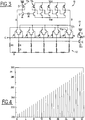
- the operation of the delay circuit 10 will be described with reference to the graph in FIG. 2 illustrating the successive delays obtained between the input signal IN and the output signal OUT by a progressive variation of the control signal C by 32 steps.
- the bits im are at the low level and have the logic value 0
- all the switches 12b are open and thus isolate the amplifier 11b and the network 12 from the output buffer 13.
- the signal IN therefore crosses only the amplifier 11a and the output buffer 13.
- the delay between the signal lN and the signal OUT corresponds to the minimum delay of the circuit 10, which is 115 picoseconds in the example of FIG. 2.
- all the bits im take the logical value 1 all the switches 12b are conducting and thus connect all the stages of the network 12 to the output B of the amplifier 11b.
- the last stage RR forms with the resistance 2R of the penultimate stage a resistance equal to R, so that by going up iteratively to the first stage we find the equivalent resistance of the network 12 equal to R. It is the resistance minimum of the network R which causes the most current to be output from the output B of the amplifier 11b and which determines the longest delay provided by the amplifier 11b, to which is added the constant delay of the amplifier 11a.
- the maximum delay corresponding to step 32 of the control signal C is 203 picoseconds. It appears from Figure 2 that the variation is close to a straight line, slightly curved between the values 5 and 17 of C and a more sensitive inflection to the values 3 and 4 of C. The steps are as fine as about 3 ps.
- the advantage of the network 12 is to offer a monotonic and quasi-linear delay control between a minimum value Tmin fixed by the amplifier 11a and a maximum value Tmax determined by the fixed value Tmin and the maximum delay which the amplifier 11b and the network 12.
- the delay is linearly controlled in steps equal to each (Tmax - Tmin) / 2 N.
- the amplifiers can all be made in DCFL or BDCFL logic and the fineness of the steps can be adjusted by the number of bits of the control signal C, a number of six bits making it possible to have 64 steps.
- the network 12 can be adapted to a type of non-linear variation.
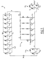
- FIGS 3 and 4 illustrate another embodiment of a delay circuit 10 according to the invention, made of MESFET transistors in DCFL logic.
- Amplifier 11a is made of a single DCFL inverter and amplifier 11b of five cascaded inverters.
- the network 12 is also made of five stages R-2R and the output buffer 13 is made of a single DCFL inverter. However, the network 12 and its connection to the outputs A and B of the amplifiers and of the output buffer 13 are changed.
- the network 12 includes the five switch transistors 12b, here connected between the respective branches 2R of the stages of the network and the output B of the amplifier 11b.
- the network likewise comprises five other switch transistors 12a connected between the respective branches 2R and the output A of the amplifier 11a.
- the network is made up of five stages R-2R and comprises an additional resistance R1 connecting the free resistance R of the first stage R-2R to one of the outputs A or B, the output A in this case, for the reasons indicated below -after.
- the connections of the switch transistors 12a and 12b with the respective stages R-2R are combined at the input of the output buffer 13.
- the control signal C comprises the five control bits im applied to the gates of the transistors 12b and five other bits of command i * -m * complementary to the bits im and applied to the gates of the transistors 12a.
- the network retains a resistance substantially equal to R, in which therefore flows a constant current I from the two amplifiers 11a and 11b in a complementary manner. This ensures very good linearity, as shown in Figure 3. According to this figure, the delays vary between about 207 and 292 ps in 32 steps of the order of 2 to 3 ps each.
- FIGS. 5 illustrates another exemplary embodiment of a delay circuit 10 according to the invention, made of MESFET transistors in BDCFL logic.
- the delay circuit 10 illustrated diagrammatically in FIG. 5 is similar to that of FIG. 3 and includes the two amplifiers 11a and 11b, the network 12 provided with switches 12a and 12b receiving the digital control signal C composed of the ten control bits im and i * -m *, and the output buffer 13.
- the amplifiers 11 a and 11b and the output buffer 13 are made of BDCFL inverters having the same structure as that of output buffer 13 of circuit 10 of FIG. 1.
- the amplifiers 11a and 11b illustrated are each made of a single inverter but have different propagation times.
- the output terminals A and B of the input amplifiers 11a and 11b are connected, on the one hand, to the potential Vss via two respective diodes, the cathode of which is at the potential Vss, so as to block the voltage of output at around 0.8 volts, and on the other hand at the two respective terminals of switches 12a and 12b.
- the output buffer 13 comprises two cascaded BDCFL inverters. Thanks to the use of BDCFL logic, the delays are essentially the same during the rise and fall times.
- FIG. 6 relates to a fourth embodiment according to the invention.
- the delay circuit 10 is made in SCFL logic (Source-Coupled FET Logic).
- the structure of circuit 10 is similar to that of FIG. 3, but here it corresponds to a differential structure and includes two complementary inputs IN and IN *, two differential amplifiers 11a, 11b, an iterative network 12 with six stages R-2R and controlled by the control signal digital C composed of ten command bits (im, i * -m *), and two complementary output buffers 13 and 13 *.
- It further comprises two fixed delay buffer amplifiers 14a and 14b connected in series and each provided with two complementary output buffers 13 and 13 *.
- variable gain amplifiers 11a and 11b and fixed delay amplifiers 14a and 14b are similar to differential amplifiers and have a well known structure, made of two symmetrical depletion transistors D and D * having their common sources.
- the drains of the two transistors D and D * are connected to two respective load resistors joined together to be connected to the supply potential Vdd via a diode.
- the respective buffers 13 and 13 * are formed by a depletion transistor D, at least one diode, an enrichment transistor E and a resistor connected successively in series between the potentials Vdd and Vss.
- the drains of transistors D and D * are connected to the respective gates of transistors D of buffers 13 and 13 *.
- the complementary outputs OUT and OUT * are supplied at the level of a cathode of a diode of the two respective buffers 13 and 13 *, in this case the diode close to the drain of the transistor E as illustrated.
- the network 12 illustrated comprises six constant current sources S each formed by an enhancement transistor E controlled by a common reference voltage Vref and five pairs of switches 12a, 12b formed by enhancement transistors controlled by the signals i * -m * for the respective switches 12a and im for the respective switches 12b.
- each pair of transistors 12a and 12b are connected to a respective branch 2R of the network 12 via a corresponding current source transistor S while the drains are respectively connected to the common sources of the amplifiers 11a and 11b through two transistors 12'a and 12'b controlled by a fixed voltage not shown so as to be conductive and which can be eliminated.
- the branch 2R of the sixth stage is connected by a current source transistor S to the supply potential Vdd to give the network 12 an equivalent resistance that is substantially constant.
- the common reference potential Vref is also applied to the gates of the current source transistors of the amplifiers 14a and 14b and of the transistors E of all the buffers 13 and 13 *.
- variable gain input amplifier 11a receives on the gates of transistors D and D * the complementary input signals IN and IN *, which are also applied to the inputs of the fixed gain input amplifier 14a.
- the intermediate output signals P1 and P1 * provided by the fixed delay buffer amplifier 14a are applied to the respective gates of the transistors D * and D of the second fixed delay buffer amplifier 14b.
- the intermediate output signals P2 and P2 * supplied by the buffer amplifier 14b are applied to the gates of the respective transistors D and D * of the second amplifier 11b.
- the states of the control bits im and i * -m * determine the delay between the complementary input signals IN, IN * and the complementary output signals OUT of the same as in circuits 10 of FIGS. 3 and 5.
- the amplifier 11b is blocked and the amplifier 11a is activated with a minimum load resistance representative of a maximum delay for this amplifier but a minimum delay for the circuit 10.
- the amplifier 11a is blocked and the amplifier 11b with the two amplifiers buffers 14a and 14b are activated with a minimum load resistance representative of a minimum delay for the amplifier 11b but maximum for the circuit 10.
- the intermediate states appear to vary very linearly.
- the subject of the invention is generally an integrated delay circuit 10 comprising two amplifiers 11a, 11b providing different delays and having a common input, and control means 12 connected to two respective terminals of the two amplifiers to vary the phase difference between the two amplifiers.
- the amplifier 11a is fast and the amplifier 11b is slow.
- the control means can be adapted to the type of control chosen.
- the control means 12 preferably comprise an iterative network R-2R including switches controlled by a digital control signal C to select the stages of the iterative network.
- the switches are simple like the switches 12b illustrated in FIG. 1 or can be paired 12a, 12b and connected to said respective terminals of the two amplifiers.
- the control means can also be adapted to the type of variation chosen.
- the switches are dimensioned so as to conduct in the stages of the iterative network a current substantially equal to l / 2 N where N represents the sequence number of the stages in the network .
- the control means keep an equivalent resistance substantially constant, otherwise means such as the branch R-R1 can be provided to give the control means an equivalent resistance substantially equal despite the variation of the signal. ordered.
- this circuit is very well suited for integration into a III-V semiconductor material with field effect transistors in DCFL and / or BDCFL logic, in which case the control means are connected to the output terminals of the two amplifiers.
- the two amplifiers can be differential amplifiers including the control means as part of a current source, the output of the delay circuit being constituted by a common output of the two amplifiers.
- it can be integrated into a III-V semiconductor material with field effect transistors (MESFET, HEMT) in SCFL logic. It can also be integrated in a monocrystalline semiconductor material, with field effect transistors, for example in CMOS, or with bipolar transistors.
- the invention relates to a delay circuit as defined above.
- the amplifier 11a could be omitted.
- the network 12 would then be a means for varying the gain of the amplifier 11b.
- the operation would then be in accordance with conventional delay circuits. This operation could also be obtained from the delay circuit 10 illustrated in FIG. 6, with a single amplifier 11a or 11b, or with the two amplifiers controlled alternately by complementary commands on the gates of the transistors 12'a and 12'b for get two respective delay variation ranges.
- other amplifiers could be added in a well known manner to increase the number of ranges.
Landscapes
- Physics & Mathematics (AREA)
- Nonlinear Science (AREA)
- Networks Using Active Elements (AREA)
- Pulse Circuits (AREA)
- Logic Circuits (AREA)
Applications Claiming Priority (2)
| Application Number | Priority Date | Filing Date | Title |
|---|---|---|---|
| FR9404331A FR2718903B1 (fr) | 1994-04-13 | 1994-04-13 | Circuit à retard réglable. |
| FR9404331 | 1994-04-13 |
Publications (1)
| Publication Number | Publication Date |
|---|---|
| EP0677924A1 true EP0677924A1 (de) | 1995-10-18 |
Family
ID=9462014
Family Applications (1)
| Application Number | Title | Priority Date | Filing Date |
|---|---|---|---|
| EP95400807A Withdrawn EP0677924A1 (de) | 1994-04-13 | 1995-04-11 | Einstellbare Verzögerungsschaltung |
Country Status (5)
| Country | Link |
|---|---|
| US (1) | US5592116A (de) |
| EP (1) | EP0677924A1 (de) |
| JP (1) | JPH0851337A (de) |
| CA (1) | CA2146196A1 (de) |
| FR (1) | FR2718903B1 (de) |
Cited By (2)
| Publication number | Priority date | Publication date | Assignee | Title |
|---|---|---|---|---|
| US5748125A (en) * | 1996-01-23 | 1998-05-05 | International Business Machines Corporation | Digital delay interpolator circuit |
| EP0777232A3 (de) * | 1995-11-29 | 1999-08-04 | Texas Instruments Incorporated | Programmierbare Zeitverzögerung für oder in Beziehung auf Halbleiterspeicher |
Families Citing this family (5)
| Publication number | Priority date | Publication date | Assignee | Title |
|---|---|---|---|---|
| KR0146082B1 (ko) * | 1995-09-22 | 1998-12-01 | 문정환 | 프로그래머블 아날로그 스위치 |
| US5990714A (en) * | 1996-12-26 | 1999-11-23 | United Microelectronics Corporation | Clock signal generating circuit using variable delay circuit |
| DE19800776C1 (de) * | 1998-01-12 | 1999-06-17 | Siemens Ag | Verzögerungsschaltung |
| JPH11259166A (ja) * | 1998-03-12 | 1999-09-24 | Nec Corp | クロックスキュー調整回路、クロックレシーバ、およびクロック伝送システム |
| US6573811B2 (en) | 2001-02-07 | 2003-06-03 | National Semiconductor Corporation | Resistor tuning network and method for microelectronic RC-based filters |
Citations (3)
| Publication number | Priority date | Publication date | Assignee | Title |
|---|---|---|---|---|
| US4795923A (en) * | 1987-11-25 | 1989-01-03 | Tektronix, Inc. | Adjustable delay circuit |
| US4797586A (en) * | 1987-11-25 | 1989-01-10 | Tektronix, Inc. | Controllable delay circuit |
| EP0306662A2 (de) * | 1987-09-08 | 1989-03-15 | Tektronix, Inc. | Einrichtung zur Erzeugung von Signalen zur Zeitverschiebungskompensation |
Family Cites Families (12)
| Publication number | Priority date | Publication date | Assignee | Title |
|---|---|---|---|---|
| US3675133A (en) * | 1971-06-21 | 1972-07-04 | Ibm | Apparatus and method independently varying the widths of a plurality of pulses |
| US3728719A (en) * | 1972-03-20 | 1973-04-17 | Us Navy | R-2r resistive ladder, digital-to-analog converter |
| US4176344A (en) * | 1975-05-28 | 1979-11-27 | Bell Telephone Laboratories, Incorporated | Integrated circuit binary weighted digital-to-analog converter |
| US4521765A (en) * | 1981-04-03 | 1985-06-04 | Burr-Brown Corporation | Circuit and method for reducing non-linearity in analog output current due to waste current switching |
| JPS60143017A (ja) * | 1983-12-29 | 1985-07-29 | Advantest Corp | クロツク同期式論理装置 |
| US4737670A (en) * | 1984-11-09 | 1988-04-12 | Lsi Logic Corporation | Delay control circuit |
| US4647906A (en) * | 1985-06-28 | 1987-03-03 | Burr-Brown Corporation | Low cost digital-to-analog converter with high precision feedback resistor and output amplifier |
| US4800365A (en) * | 1987-06-15 | 1989-01-24 | Burr-Brown Corporation | CMOS digital-to-analog converter circuitry |
| JPH0232731A (ja) * | 1988-07-16 | 1990-02-02 | Chubu Seimitsu:Kk | モータの構造 |
| US5272729A (en) * | 1991-09-20 | 1993-12-21 | International Business Machines Corporation | Clock signal latency elimination network |
| FR2690022B1 (fr) * | 1992-03-24 | 1997-07-11 | Bull Sa | Circuit a retard variable. |
| US5381063A (en) * | 1992-11-13 | 1995-01-10 | Medtronic, Inc. | AC offset compensation for active LCD drivers |
-
1994
- 1994-04-13 FR FR9404331A patent/FR2718903B1/fr not_active Expired - Fee Related
-
1995
- 1995-04-03 CA CA002146196A patent/CA2146196A1/fr not_active Abandoned
- 1995-04-04 JP JP7079024A patent/JPH0851337A/ja active Pending
- 1995-04-05 US US08/417,258 patent/US5592116A/en not_active Expired - Fee Related
- 1995-04-11 EP EP95400807A patent/EP0677924A1/de not_active Withdrawn
Patent Citations (3)
| Publication number | Priority date | Publication date | Assignee | Title |
|---|---|---|---|---|
| EP0306662A2 (de) * | 1987-09-08 | 1989-03-15 | Tektronix, Inc. | Einrichtung zur Erzeugung von Signalen zur Zeitverschiebungskompensation |
| US4795923A (en) * | 1987-11-25 | 1989-01-03 | Tektronix, Inc. | Adjustable delay circuit |
| US4797586A (en) * | 1987-11-25 | 1989-01-10 | Tektronix, Inc. | Controllable delay circuit |
Cited By (2)
| Publication number | Priority date | Publication date | Assignee | Title |
|---|---|---|---|---|
| EP0777232A3 (de) * | 1995-11-29 | 1999-08-04 | Texas Instruments Incorporated | Programmierbare Zeitverzögerung für oder in Beziehung auf Halbleiterspeicher |
| US5748125A (en) * | 1996-01-23 | 1998-05-05 | International Business Machines Corporation | Digital delay interpolator circuit |
Also Published As
| Publication number | Publication date |
|---|---|
| US5592116A (en) | 1997-01-07 |
| FR2718903A1 (fr) | 1995-10-20 |
| JPH0851337A (ja) | 1996-02-20 |
| CA2146196A1 (fr) | 1995-10-14 |
| FR2718903B1 (fr) | 1996-05-24 |
Similar Documents
| Publication | Publication Date | Title |
|---|---|---|
| CA2137340C (fr) | Arbre de portes logique ou - exclusif et multiplieur de frequence l'incorporant | |
| CA2057806C (fr) | Dispositif de retard reglable | |
| EP0474534B1 (de) | Schaltung mit einstellbarer Zeitkonstante und ihre Anwendung für einstellbare Verzögerungsleitung | |
| EP0130645B1 (de) | Frequenzteiler durch zwei | |
| FR2732837A1 (fr) | Circuit d'amplification differentielle, circuit integre a semiconducteur le comprenant et procede d'enlevement de bruit correspondant | |
| EP0677924A1 (de) | Einstellbare Verzögerungsschaltung | |
| EP0237094A1 (de) | Vordiffundierte Gatterfeld-Halbleitervorrichtung für speziell hergestellte Schaltungen | |
| EP0336460B1 (de) | Kippschaltung zum Teilen der Frequenz durch 2 | |
| EP0493150B1 (de) | Einstellbare Verzögerungsanordnung | |
| FR2792459A1 (fr) | Dispositif a semiconducteur ayant un transistor mis | |
| EP0410908B1 (de) | Koppelpunkt für Schaltmatrix | |
| FR2648643A1 (fr) | Circuit d'interface entre deux circuits numeriques de natures differentes | |
| FR2477802A1 (fr) | Circuit d'amplification | |
| EP0347985B1 (de) | Allpasstyp-Schaltung für ultrahohe Frequenzen | |
| EP0187584B1 (de) | Logisches Koinzidenztor und dieses verwendende logische sequentielle Schaltungen | |
| EP0434495A1 (de) | Vorladeschaltung für Speicherbus | |
| FR2656174A1 (fr) | Procede et dispositif de compensation de la derive en courant dans un circuit integre mos, et circuit integre en resultant. | |
| EP0899921B1 (de) | Symmetrischer Leitungstreiber | |
| EP0203645A1 (de) | Integrierte Digital/Analog-Wandlerschaltung mit Gerät zur Glitchreduzierung | |
| FR2572234A1 (fr) | Dispositif de decalage de potentiel pour des circuits integres au gaas | |
| FR2653277A1 (fr) | Circuit integre logique, a temps de basculement reglable. | |
| FR2573939A1 (fr) | Circuit multiplexeur de signaux integre a quatre voies d'entree | |
| EP0187572B1 (de) | Begrenzerschaltung für logische Spannungsabweichungen und eine solche Begrenzerschaltung enthaltende logische Schaltung | |
| EP0349028A2 (de) | Integrierte Halbleiterschaltung mit einem differentiellen Paar von FETs | |
| EP0497068A1 (de) | Schwellwert-Schaltung |
Legal Events
| Date | Code | Title | Description |
|---|---|---|---|
| PUAI | Public reference made under article 153(3) epc to a published international application that has entered the european phase |
Free format text: ORIGINAL CODE: 0009012 |
|
| AK | Designated contracting states |
Kind code of ref document: A1 Designated state(s): AT BE CH DE ES FR GB IT LI NL SE |
|
| 17P | Request for examination filed |
Effective date: 19960418 |
|
| 17Q | First examination report despatched |
Effective date: 19970402 |
|
| STAA | Information on the status of an ep patent application or granted ep patent |
Free format text: STATUS: THE APPLICATION IS DEEMED TO BE WITHDRAWN |
|
| 18D | Application deemed to be withdrawn |
Effective date: 19990223 |