EP0677190B1 - Für fensterumgebungsoperationen entworfenes rasterpuffersystem - Google Patents
Für fensterumgebungsoperationen entworfenes rasterpuffersystem Download PDFInfo
- Publication number
- EP0677190B1 EP0677190B1 EP94932066A EP94932066A EP0677190B1 EP 0677190 B1 EP0677190 B1 EP 0677190B1 EP 94932066 A EP94932066 A EP 94932066A EP 94932066 A EP94932066 A EP 94932066A EP 0677190 B1 EP0677190 B1 EP 0677190B1
- Authority
- EP
- European Patent Office
- Prior art keywords
- data
- frame buffer
- color
- circuitry
- pixel
- Prior art date
- Legal status (The legal status is an assumption and is not a legal conclusion. Google has not performed a legal analysis and makes no representation as to the accuracy of the status listed.)
- Expired - Lifetime
Links
Images


Classifications
-
- G—PHYSICS
- G06—COMPUTING; CALCULATING OR COUNTING
- G06F—ELECTRIC DIGITAL DATA PROCESSING
- G06F12/00—Accessing, addressing or allocating within memory systems or architectures
- G06F12/02—Addressing or allocation; Relocation
- G06F12/06—Addressing a physical block of locations, e.g. base addressing, module addressing, memory dedication
-
- G—PHYSICS
- G09—EDUCATION; CRYPTOGRAPHY; DISPLAY; ADVERTISING; SEALS
- G09G—ARRANGEMENTS OR CIRCUITS FOR CONTROL OF INDICATING DEVICES USING STATIC MEANS TO PRESENT VARIABLE INFORMATION
- G09G5/00—Control arrangements or circuits for visual indicators common to cathode-ray tube indicators and other visual indicators
- G09G5/02—Control arrangements or circuits for visual indicators common to cathode-ray tube indicators and other visual indicators characterised by the way in which colour is displayed
- G09G5/024—Control arrangements or circuits for visual indicators common to cathode-ray tube indicators and other visual indicators characterised by the way in which colour is displayed using colour registers, e.g. to control background, foreground, surface filling
-
- G—PHYSICS
- G09—EDUCATION; CRYPTOGRAPHY; DISPLAY; ADVERTISING; SEALS
- G09G—ARRANGEMENTS OR CIRCUITS FOR CONTROL OF INDICATING DEVICES USING STATIC MEANS TO PRESENT VARIABLE INFORMATION
- G09G5/00—Control arrangements or circuits for visual indicators common to cathode-ray tube indicators and other visual indicators
- G09G5/02—Control arrangements or circuits for visual indicators common to cathode-ray tube indicators and other visual indicators characterised by the way in which colour is displayed
- G09G5/022—Control arrangements or circuits for visual indicators common to cathode-ray tube indicators and other visual indicators characterised by the way in which colour is displayed using memory planes
-
- G—PHYSICS
- G09—EDUCATION; CRYPTOGRAPHY; DISPLAY; ADVERTISING; SEALS
- G09G—ARRANGEMENTS OR CIRCUITS FOR CONTROL OF INDICATING DEVICES USING STATIC MEANS TO PRESENT VARIABLE INFORMATION
- G09G5/00—Control arrangements or circuits for visual indicators common to cathode-ray tube indicators and other visual indicators
- G09G5/36—Control arrangements or circuits for visual indicators common to cathode-ray tube indicators and other visual indicators characterised by the display of a graphic pattern, e.g. using an all-points-addressable [APA] memory
- G09G5/39—Control of the bit-mapped memory
- G09G5/393—Arrangements for updating the contents of the bit-mapped memory
Definitions
- This invention relates to computer systems and, more particularly, to methods and apparatus for providing a frame buffer capable of receiving, manipulating and transferring data for display at a high rate of speed when used in a system displaying a plurality of applications simultaneously in windows on an output display device.
- a problem which has been discovered by designers of graphics accelerator circuitry is that a great deal of the speed improvement which is accomplished by the graphics accelerator circuitry is negated by the frame buffer circuitry into which the output of the graphics accelerator is loaded for ultimate display on an output display device.
- a frame buffer offers a sufficient amount of random access memory to store one frame of data to be displayed.
- transferring the data to and from the frame buffer is very slow because of the manner in which the frame buffers are constructed.
- Various improvements have been made to speed access in frame buffers. For example, two-ported VRAM has been substituted for DRAM so that information may be taken from the frame buffer while it is being loaded.
- a flash mode has been devised for allowing an entire row of a display to be written with a single color.
- This mode is useful when the entire display is being cleared but cannot provide clipping to limited areas and so is not useful when windows are displayed on the screen of an output display. Since the design of prior art frame buffers has produced a substantial bottle neck to rapid display of data in modem windowing systems, a new design of frame buffers allowing substantially increased display speed is desirable.
- an object of the present invention to provide a new design of frame buffer capable of rapidly handling the data transferred to it for display in a system which presents a plurality of applications in separate windows on an output display device.
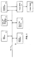
- Figure 1 is a block diagram illustrating a computer system including the present invention.
- FIG. 2 is a block diagram of a frame buffer designed in accordance with prior art.
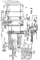
- FIG. 3 is a block diagram of a frame buffer designed in accordance with the present invention.
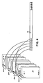
- Figure 4 is a diagram illustrating operational details of a portion of the frame buffer of Figure 3.
- Figure 5 is a flow chart illustrating a method in accordance with the invention.
- the manipulations performed are often referred to in terms, such as adding or comparing, which are commonly associated with mental operations performed by a human operator. No such capability of a human operator is necessary or desirable in most cases in any of the operations described herein which form part of the present invention; the operations are machine operations.
- Useful machines for performing the operations of the present invention include general purpose digital computers or other similar devices. In all cases the distinction between the method operations in operating a computer and the method of computation itself should be borne in mind.
- the present invention relates to a method and apparatus for operating a computer in processing electrical or other (e.g. mechanical, chemical) physical signals to generate other desired physical signals.
- the system 10 includes a central processor 11 which carries out the various instructions provided to the computer 10 for its operations.
- the central processor 11 is joined to a bus 12 adapted to carry information to various components of the system 10.
- main memory 13 which is typically constructed of dynamic random access memory arranged in a manner well known to those skilled in the prior art to store information being used by the central processor during the period in which power is provided to the system 10.
- read only memory 14 which may include various memory devices (such as electrically programmable read only memory devices (EPROM or similar devices)) well known to those skilled in the art which are adapted to retain memory condition in the absence of power to the system 10.
- the read only memory 14 typically stores various basic functions used by the processor 11 such as basic input/output processes and startup processes.
- long term memory 16 Also connected to the bus 12 are various peripheral components such as long term memory 16.
- long term memory 16 typically electro-mechanical hard disk drives
- circuitry such as a frame buffer 17 to which data may be written that is to be transferred to an output device such as a monitor 18 for display.
- the frame buffer may be considered to include in addition to the various memory planes necessary to store information, various circuitry well known to those skilled in the art for controlling the scan of information to the output display.
- FIG. 2 illustrates a frame buffer 17 constructed in accordance with the prior art.
- a frame buffer 17 includes a dynamic random access memory array designed to store information defining pixels on the output display.
- data is written to or read from the frame buffer 17 on the conductors of the data bus 12.
- the frame buffer 17 is written, all of the data conductors of the bus transfer the binary data to be stored as pixel information.
- thirty-two bits of information may be written on the bus and appear at thirty-two input pins to the frame buffer memory. This data may define one or more pixels depending upon the number of bits required to define a pixel in the particular display mode.
- each pixel displayed requires eight bits of data; and thirty-two bits of data on the data conductors of the bus are capable of defining four pixels in each individual access.
- Writing pixel data one (or four) pixels at a time is a relatively slow method of filling the frame buffer with data to be written to the display. This is, however, the usual mode of writing pixel data to the display.
- This normal mode is typically used in any process which varies the display on a pixel by pixel basis or to describe any graphical image which uses more than two colors in a window.
- some prior art frame buffers also have apparatus which allows a mode of operation (referred to as "block mode") in which each of the data conductors controls access to four bits representing a pixel color value.
- block mode allows data representing a color value to be written simultaneously to a plurality of individual pixel positions in the memory.
- the information written to the array on the data conductors is control information used to enable writing to memory positions representing particular pixel positions and to ignore other pixel positions.
- the prior art frame buffer 17 of Figure 2 has a plurality of data input conductors 23 and a four bit color register 19.
- a four bit color value to be stored as pixel data in data positions in an array 20 of the frame buffer 17 is written into the color register 19.
- Data transferred to the frame buffer 17 on the data conductors 23 indicates the positions of pixels which are to be written and of those pixels which are not to be written. For example, if a data conductor 23 carries a zero value, then the pixel position controlled by that conductor is not written. If a data conductor 23 carries a one value, then the four bit color value from the color register 19 is written into the pixel position. In this way, selected ones of a number of individual pixels may be written at once using the color value stored in the color register 19.
- the foreground color is placed in the color register, and the foreground pixels are written to the row.
- the background color is again placed in the color register, and the entire second row of the particular window is cleared.
- the background color is again replaced in the color register with the foreground color, and the foreground pixels are written for the second row. This continues until all of the rows of the window have been written with both of the colors necessary to the display.
- each access of the frame buffer requires both a row address strobe (RAS) cycle of 120 nanoseconds and a column address strobe (CAS) cycle of 20 nanoseconds. This is true for accessing the frame buffer to load the color register and for accessing the memory positions in the frame buffer.
- RAS row address strobe
- CAS column address strobe
- a plurality of pixels may be read or written in the same row as long as no other operation intervenes with only a CAS cycle required for each group of thirty-two pixels.
- the same RAS/CAS sequence is used for operations other than reading and writing to the memory cells, to load the color register with background color takes a first 120 nanoseconds, writing the background color takes another 120 nanoseconds, reloading the color register with foreground color takes another 120 nanoseconds, and writing the foreground color takes another 120 nanoseconds.
- One of the slowest operations performed in such a prior art frame buffer is the scrolling of data.
- rows of data are moved up or down on the output display. Since the data describing the pixels which are displayed on an output display device is stored in a frame buffer, scrolling requires that the pixel data in the frame buffer describing a row of the display be read from the frame buffer by the central processor and written back to another position in the frame buffer.
- thirty-two bits of data are read from the frame buffer simultaneously in an operation that typically requires 140 nanoseconds; typically an extra 20 ns. is required to read when data must be taken off of the frame buffer chip.
- Another problem with the prior art frame buffers relates to the circuitry by which data is taken from the array and transferred to the output display circuitry.
- the circuitry requires a shift register output stage sufficient to hold an entire row of pixels on the display.
- a row of pixel data is transferred into this shift register circuitry and shifted out to the display on a pixel by pixel basis.
- a shift register sufficient to hold an entire row of pixels takes a large amount of space on the frame buffer. This space is space which is then not available to accomplish other, often more useful, techniques.
- FIG. 3 there is illustrated a detailed block diagram of a frame buffer 50 designed in accordance with the present invention while Figure 5 illustrates a method in accordance with the invention.
- Figure 3 illustrates a circuit board upon which reside the various components of a frame buffer 50.
- the frame buffer 50 includes a plurality of memory cells 53 such as field effect transistor devices arranged to provide a dynamic random access memory array 52.
- the arrangement of the cells 53 constituting the array 52 is developed in accordance with principals well known to those skilled in the art. It is adapted to provide a sufficient number of addressable memory cells 53 in the array 52 to describe the number of pixels to be presented on an output display device in a particular mode of operation.
- the array 52 may include a total of thirty-two planes (only the first is illustrated in detail in Figure 3), each plane including 256 rows, each row including 1024 memory devices; such an arrangement allows the storage of color data sufficient to display thirty-two bit color in a 512 X 512 pixel display on a color output display terminal.
- the frame buffer 50 may display both thirty-two bit and sixteen bit color modes as well as other modes well known to those skilled in the art, the frame buffer 50 is particularly adapted for use with pixels displaying color in eight bit color modes.
- the frame buffer 50 includes row and column decode circuitry for decoding the addresses furnished by a controller such as a central processor and selecting individual memory cells in each plane of the array 52 to define the various pixels which may be represented on an output display device.
- the address decoding circuitry includes row decoding circuitry 54 and column decoding circuitry 56 by which individual memory cells 53 representing bits of individual pixels may be selected for reading and writing.
- data conductors 58 which may be connected to a data bus to provide data to be utilized in the array 52.
- thirty-two data conductors 58 are provided although this number will vary with the particular computer system. The number thirty-two matches the number of bits which are transferred to indicate the color of a single pixel of the largest number of bits expected to be used by the display system in the most accurate color mode of operation.
- each group of thirty-two bits defines one or more color values to be displayed at one or more pixel positions on the output display.
- the thirty-two bits carried by the data conductors 58 in normal write mode may define four pixel positions on the display.
- the thirty-two bits of the data conductors 58 carry information defining a single pixel position on the display.
- one of the data conductors 58 of the bus is connected through an input data buffer to all of eight multiplexors 62 in each plane of the array.
- the embodiment illustrated in Figure 3 is particularly adapted to be used in a system utilizing eight bit color modes; and, to this end, the system utilizes eight individual multiplexors 62 in each plane of the frame buffer 50 for selecting particular write input data.
- Each of these multiplexors 62 has its output connected to one of eight tri-state write drivers 73 which furnishes an output signal via a write enable switch such as a transmission gate 71 on a conductor 66 connected to every eighth column of the particular plane of the array.
- Each of the multiplexors 62 selects the source of the data to be transferred to the array 52 in each plane depending on the mode of operation selected. Thus, in normal mode, the data bit is selected directly from the data conductor 58 for that plane of the array.
- the bit is transferred from one of the multiplexors 62 by one of the eight write drivers 73 to a particular selected column and written to the memory cell 53 at that column and the selected row. Since a bit may be written in each of thirty-two planes of the array, thirty-two bits may be written from the bus conductors 58 (one to each plane) as one thirty-two bit pixel, two sixteen bit pixels, or four eight bit pixels, depending on the color mode in which the system is operating.
- a mode control circuit 68 is provided to designate the particular mode of operation in which the frame buffer is to operate.
- four control signals DSF0-DSF3 are furnished along with write enable and output enable signals. The combination of these signals produces the particular output mode control signals in a manner well known to those skilled in the prior art.
- a particular address is transferred on the address bus to select a particular row and column.
- the row address is furnished to the row decode circuitry 54 by a row address latch 51 on the falling edge of a row address strobe signal.
- the row address causes power to be furnished to all of the memory cells 53 joined to the particular row of the array in each of the selected planes.
- the value of each memory cell in the row is sensed by a sense amplifier 63 for each column of the array.
- the sense amplifiers 63 are turned on, and each sense amplifier 63 drives the value sensed back to refresh the memory cell 53 in the selected row.
- the column address is transferred from a latch 57 and applied to the appropriate switches 67 of the column decode circuitry 56 to select the appropriate columns in each plane to be written.
- the column address is ten bits. Of these ten bits, the higher valued seven bits CA3-9 of the column address are used to select a group of eight adjacent columns.
- the normal mode write control signal at each of the multiplexors 62 causes the data signal furnished on the single conductor 58 associated with that plane to be transferred from the data input buffer by each of the eight multiplexors 62.
- One of the signals produced by the multiplexors 62 is amplified by a single one of the write drive amplifiers 73 and transferred to the addressed memory cell 53 in that plane of the array.
- the lower three bits CA0-2 of the column address from the latch 57 select the particular one of the eight write drive amplifiers 73 which transfers the data bit to a single one of the columns. Since each of the conductors 58 associated with each plane of the array 52 carries an individual bit for the memory cell at the selected row and column, the pixel value (or values) will be transferred to the appropriate column and row position in each plane of the array.
- the row and column addresses are transferred to the decode circuitry 54 and 56.
- a row address is selected on the falling edge of the RAS signal; and the entire row of memory cells in each selected plane of the array 52 is refreshed.
- the higher valued seven bits CA3-9 of the column address are applied to the appropriate switches 67 of the column decode circuitry 56 to select the eight adjacent columns in each plane which have been addressed and are to be read.
- the condition of the memory cells 53 in each of these eight columns of each selected plane are sensed by a second set of output sense amplifiers 75.
- the output of a particular one of the columns is selected by a multiplexor 79 in each plane which is controlled by the normal mode read signal and the value of the lower three bits CA0-2 of the column address. This causes the condition of a particular memory cell 53 to be transferred to a particular one of the conductors 58 of the data bus associated with that plane of the array 52.
- the frame buffer 50 carries out the typical normal read and write modes of operation.
- the frame buffer 50 also includes at least a pair of color value registers C0 and C1 which are utilized to store color values which may be used in color block modes of operation described hereinafter in which a plurality of storage positions may be written simultaneously.
- Each plane of the array includes a one bit register C0 and a one bit register C1 for storing one bit of a color value. Since each plane includes one bit for each register, each register C0 and C1 includes a total of thirty-two bits in the preferred embodiment.
- an entire eight bit color value may be stored in the registers C0 and C1 residing on eight planes
- an entire sixteen bit color value may be stored in the registers C0 and C1 residing on sixteen planes
- an entire thirty-two bit color value may be stored in the registers C0 and C1 of thirty-two planes of the frame buffer 50.
- the color pattern for a particular eight bit color value may be repeated four times in each color register (similarly a sixteen bit color may be repeated twice).
- the color registers C0 and C1 may be selectively addressed so that they may be loaded by data furnished on the conductors 58 of the data bus; as may be seen, switches are provided in each cell plane to allow loading of the registers C0 and C1 with color value data from the data conductors 58.
- the details of the color block registers and their use are described in the U.S. patent 5,504,855. entitled Apparatus For Providing Fast Multi-Color Storage In A Frame Buffer. Priem et al.
- the color registers C0 and C1 provide color values which the multiplexors 62 may select for writing to the cells of the memory array instead of the data furnished on the conductors 58.
- the selection by the multiplexors 62 of color values from the registers C0, C1 or of pixel data from the conductors 58 depends on the particular color mode of operation, a value indicated by control signals furnished by the central processor or by an associated graphical accelerating device.
- the data conductors 58 When a color block mode of operation is indicated by the control signals, the data conductors 58, rather than carrying pixel data, carry enabling signals to indicate pixel positions in the array 52 to which the color values held in the registers C0 and C1 are to be written. These color values are initially loaded from the data conductors 58 of each array plane of the frame buffer 50 in response to a load color register control signal. Since two color registers C0 and C1 are provided in the preferred embodiment, a total of four color block modes of operation are possible. These modes are referred to as color 0 mode, color 1 mode, color 0&1 mode, and color 1&0 mode. As will be seen, substantial time is saved with any of these modes of operation simply through the lack of a requirement to load the color value registers for writing to each row of the display.
- the control data appearing on the conductors 58 is sent to a pixel mask register 55.
- the bits of the pixel mask register 55 are used in the manner illustrated in Figure 4 in each of the array planes to control all of the drivers 73 controlling transfer of data to a particular pixeL Since the example considered involves eight bit color and assuming that the first eight columns have been selected by the column address, the bits defining the first pixel lie in the first column in the selected row and the first eight planes of that column.
- the first pixel P1 in the pixel mask register 55 controls the appropriate drivers 73 controlling the first column and the first eight planes to transfer the color to these bit positions in the array from the color value register C0. Consequently, with one row and eight columns selected, a total of thirty-two eight bit color pixels may be written simultaneously with the value stored in the color value register C0.
- a frame buffer 30 for a display which is 1024 X 780 pixels and eight bits deep, may be cleared approximately thirty-two times faster than individual pixels may be written one by one to the frame buffer 50.
- This mode is also useful for clipping since a color value may be written to pixel positions inside a window area while the pixel positions outside that window area are not enabled.
- Color 1 mode is similar to color 0 mode except that if a one value is transferred on a particular data conductor 58, then the value in the color register C1 is written to the storage positions which define the pixel addressed for that conductor 58. The value in the color register C1 is also transferred to all other storage positions at addresses enabled by one values transferred on the data conductors 58. On the other hand, no color value is written to the pixel positions to which a zero is transferred on the data conductors.
- the two color registers C0 and C1 may be loaded prior to manipulating any portion of a window and are always available, a series of pixels (e.g., thirty-two) may be written and clipped in two accesses without any need to reload color registers. Background color may be written in a first access and foreground color written in a second access without any need to reload a color register between accesses.
- the provision of the two color value registers allows a number of new methods of writing data to the frame buffer to be practiced in addition the color modes described.
- block modes are provided by which an entire row of pixels may be written from the color registers in one color with clipping or in two colors undipped. These modes are referred to as block 256, block 512 and block 1024 modes and are described in detail in the U.S. patent 5,533,187 entitled Multiple Block Mode Operations In A Frame Buffer System Designed For Windowing Operations , Priem et al.
- each data conductor determines the color value which is written to thirty-two adjacent eight bit pixel positions. This is accomplished by the column address selecting one quarter of the total of columns (256) in each plane of the array simultaneously. Then each of the pixels connected to each of these columns receives the single color value in a color value register designated by the value carried on the data conductor in the particular color mode. It will be seen that in block 256 mode a total of thirty-two times thirty-two eight bit pixels (1024 pixels) are affected at once by each write access. This is a typical number of pixels in a row of a modern computer color monitor. Thus, each access of eight bit pixels in block 256 mode may write all of the pixels in a 1024 pixel row. It will be appreciated that this mode may be used to very rapidly clear an entire screen or to write a pattern which varies in thirty-two bit blocks on the screen.
- a second additional mode is referred to as block 512 mode.
- each data conductor affects the value of data written to thirty-two adjacent sixteen bit pixel positions.
- the column address selects a total of half the columns in each plane simultaneously. This mode requites the increase in number of selection conductors, multiplexors 62, and other components discussed above to sixteen.
- This mode is used with the block 16 mode in the same manner that block 256 mode is used with block 8 mode to rapidly write to an entire row within a clipped window area of the display.
- a third additional mode is referred to as block 1024 mode. In block 1024 mode, all of the columns in each plane are selected simultaneously by the column address.
- each data conductor affects the value of data written to thirty-two adjacent thirty-two bit pixel positions.
- This mode is used with the block 32 mode in the same manner that block 256 mode is used with block 8 mode to rapidly write to an entire row within a clipped window area of the display.
- Each of these modes provides useful functions in the same manner as does block 256 mode but for configurations of frame buffers storing data describing sixteen bit and thirty-two bit pixels.
- the frame buffer 50 of Figure 3 includes output circuitry by which pixel data is shifted to an output display device (not shown in the figure).
- the shift register 80 in each plane includes a total of sixty-four bit positions. Thus, the register totals 256 bytes in the thirty-two planes of the preferred embodiment, a value equivalent to one-fourth of a row on a display having 1024 pixel positions in a row.
- the data in the register 80 is then shifted a bit at a time from each plane by another multiplexor 82 to a circuitry controlling the display of the pixel data on an output display device. It will be recognized that this shift register is substantially smaller than that typically used at the output of a frame buffer and consequently uses much less circuit board area.
- the frame buffer 50 also includes circuitry designed to provide an extremely rapid scrolling operation.
- the scrolling operation is described in detail in U.S. patent 5,805,133 entitled METHOD AND APPARATUS FOR INCREASING THE RATE OF SCROLLING IN A FRAME BUFFER SYSTEM DESIGNED FOR WINDOWING OPERATIONS , Priem et al - That scrolling operation is described, in general, at this point in order to explain the use of the various circuitry of the frame buffer.
- a scroll mode signal is initiated by the controlling circuitry (central processor or graphics accelerator); and an address is furnished to the row and column decode circuitry to designate the particular data to be scrolled.
- the scroll mode may cause a particular row to be selected at the falling edge of a RAS signal as in normal mode of operation and the memory cells of that row to be refreshed.
- the higher order bits of the column address are used to select eight adjacent columns of the address.
- the mode signal at the array of transmission gates 77 of each plane causes the data in the memory cells of each of the eight columns selected to be transferred to a first eight bit latch shown as latch 0 in the figure.
- a next sequential address causes the data in the memory cells of each of the next eight columns to be selected and to be transferred to a second eight bit latch shown as latch 1 in the figure. This continues for two more read operations which select two more sets of eight memory cells in each plane and place the results read in third and fourth eight bit latches latch 2 and latch 3.
- each latch 0-3 is connected so that its individual bits may be selected by a multiplexor 81 to be furnished to the multiplexors 62.
- one of the latches 0-3 is illustrated with each of its bit positions furnishing input to each of the eight individual multiplexors 62 of that memory plane. This allows four sequential write operations to four consecutive addresses, taking approximately 180 ns., to write the data being scrolled back to the new row positions in the array 52 to which the row is addressed.
- the scroll mode control signal causes the higher bits of the column address to select the appropriate eight adjacent columns in each write operation. The scroll mode control signal then selects all of the columns using the drivers 73 and the write enable switches 71.
- each write back operation used in scrolling the values in each of the individual bit latches 0-3 are then driven onto the array by overdriving the sense amplifiers 63 to establish the new values at the selected memory positions in the appropriate cells of the array.
- the total time required to read and write back the data to scroll 128 pixels is only 180 ns. while a row requires 1440 ns., approximately one-85th of the time required to scroll in prior art arrangements.
- An additional facility of the invention allows it to clip pixel data to fit windows in which that data is stored at the same time that scrolling is taking place. It will have been noted that during any period in which scrolling is occurring, the conductors 58 on the data bus are not being used for the scrolling. By sending enabling signals on the data conductors 58 to the write enable gates 71 of each array, clipping may be accomplished. For example, if a first data conductor 58 carries a zero indicating that a write is not to occur and that signal is applied to disable the transmission gates 71 connected to all of the conductors 66 (one in each plane of the array 52) affecting the bits of a particular pixel, then the bits in the particular latch bit position will not be written. Thus an entire pixel may be clipped. If all of the data conductors controlling pixel positions outside a window carry zero values, then the entire area outside a window may be clipped while the scrolling is occurring.
Landscapes
- Engineering & Computer Science (AREA)
- Theoretical Computer Science (AREA)
- Physics & Mathematics (AREA)
- General Physics & Mathematics (AREA)
- Computer Hardware Design (AREA)
- General Engineering & Computer Science (AREA)
- Controls And Circuits For Display Device (AREA)
- Digital Computer Display Output (AREA)
Claims (13)
- Ein Einzelbildpuffer (50), der so ausgebildet ist, daß er mit einem Datenbus und einem Ausgabedisplay in einem Computersystem gekoppelt werden kann, wobei der Einzelbildpuffer aufweist:gekennzeichnet durch:ein Array (52) von Speicherzellen (53) zum Speichern von auf dem Ausgabedisplay anzuzeigenden Daten;erste und zweite Farbwertregister (C0,C1);eine latch-speichernde Schaltung zum Speichern von Pixeldaten, die eine Mehrzahl von auf dem Ausgabedisplay anzuzeigenden Pixeln definieren, wobei aus dem Array zu lesende Daten und in das Array zu schreibende Daten in der latch-speichernden Schaltung gespeichert werden;ein Pixelmaskenregister;eine Schaltung zum Schreiben von Pixeldaten aus dem Array (52)) in die latch-speichernde Schaltung und eine mit der latch-speichernden Schaltung und den Farbwertregistern gekoppelte Schaltung zum Auswählen von Pixeldaten zum gleichzeitigen Schreiben in eine Mehrzahl von Speicherpositionen in dem Array (52) aus den ersten und zweiten Farbwertregistern gleichzeitig oder aus der latch-speichernden Schaltung, wobei jede Speicherposition einer Pixelposition des Ausgabedisplays entspricht.
- Ein Einzelbildpuffer nach Anspruch 1, bei welchem die Schaltung zum Auswählen von Pixeldaten zum Schreiben aus den Farbwertregistern gleichzeitig oder aus der latch-speichernden Schaltung in eine Mehrzahl von Speicherpositionen in dem Array aufweist:eine Mehrzahl von Multiplexern (62), die mit jedem der Farbwertregister und mit der latch-speichernden Schaltung verbunden sind; undeine Quelle von Steuersignalen, die die Multiplexer (62) veranlassen, Farbwerte aus den Farbwertregistern (C0,C1) oder Pixeldaten aus der latch-speichernden Schaltung in Abhängigkeit von einem Betriebsmodus auszuwählen, wobei der Betriebsmodus ein durch die Steuersignale angezeigter Wert ist.
- Ein Einzelbildpuffer nach Anspruch 2, bei welchem die Quelle der Steuersignale zum Veranlassen der Multiplexer zum Auswählen von Pixeldaten aus den Farbregistern oder aus den Latch-Speichern eine Schaltung zum Übertragen von Steuersignalen auf dem Datenbus umfaßt.
- Ein Einzelbildpuffer nach Anspruch 2, ferner aufweisend eine Schaltung, die die Multiplexer veranlaßt, Pixeldaten von dem Datenbus auszuwählen.
- Ein Einzelbildpuffer nach Anspruch 1, ferner aufweisend ein Schieberegister, das eine Anzahl von Speicherpositionen zur Verfügung stellt, die geringer ist als die Anzahl von Pixeln in einer Zeile einer Anzeige; und
eine Schaltung zum Schreiben von Pixeldaten in das Schieberegister aus dem Array zur Präsentation auf einem Ausgabedisplay. - Ein Einzelbildpuffer nach Anspruch 1, bei welchem das Array von Speicherzellen in einer Mehrzahl von Ebenen angeordnet ist und der ferner eine Schaltung zum Auswählen irgendeiner der mehreren Ebenen für einen Zugriff aufweist.
- Ein Einzelbildpuffer nach einem der Ansprüche 1 bis 6, wobei der Einzelbildpuffer ferner aufweist:wobei die latch-speichernde Schaltung so ausgebildet ist, daß sie Pixeldaten speichert, die einen wesentlichen Teil einer Zeile von auf dem Ausgabedisplay anzuzeigenden Pixeldaten äquivalent sind;eine Adreßdekodierschaltung zum Steuern eines Zugriffs auf das Array, wobei die Adreßdekodierschaltung eine Spaltenadreßdekodierschaltung zum Auswählen von Gruppen benachbarter Spalten in dem Array einschließt;eine Mehrzahl von Schaltungen zum Auswählen zum Schreiben in jede der Spalten irgendeiner der Gruppen benachbarter Spalten;
eine Schaltung zum Schreiben von Pixeldaten aus ausgewählten Gruppen benachbarter Spalten des Arrays in die latch-speichernde Schaltung. - Ein Computersystem, aufweisend:einen Datenbus;ein Ausgabedisplay; undeinen Einzelbildpuffer nach einem der Ansprüche 1 bis 6.
- Ein Verfahren zum Betreiben eines Einzelbildpuffers, umfassend die Schritte:Speichern von Daten in ersten und zweiten Farbwertregistern, die jeweils einen Farbwert von in dem Einzelbildpuffer zu speichernden Pixeln definieren;Speichern von Daten in einer latch-speichernden Schaltung, die einen Wert einer Mehrzahl von in dem Einzelbildpuffer gespeicherten Pixeln definieren;Speichern von Daten in einem Pixelmaskenregister (55), um Pixel anzuzeigen, zu welchen Farbwerte aus einem Farbwertregister zur Speicherung in dem Einzelbildpuffer (50) geschrieben werden sollen;Bereitstellen von Pixelwerten definierenden Daten auf einem Datenbus, um einen Farbwert wenigstens eines in dem Einzelbildpuffer zu speichernden Pixels anzuzeigen;Bereitstellen einer Mehrzahl von Steuersignalen zum Auswählen zwischen den Daten in den Farbwertregistern und der latch-speichernden Schaltung für irgendeine Operation der Speicherung in dem Einzelbildpuffer; undAuswählen von Pixeldaten zum gleichzeitigen Schreiben aus den ersten und zweiten Farbwertregistern gleichzeitig oder aus der latch-speichernden Schaltung in eine Mehrzahl von Speicherpositionen in dem Array (52), wobei jede Position einer Pixelposition des Ausgabedisplays entspricht.
- Ein Verfahren zum Auswählen von in einen Einzelbildpuffer zu übertragenden Daten nach Anspruch 9, bei welchem der Schritt des Bereitstellens von Steuersignalen umfaßt:Liefern von wenigstens drei unabhängigen Steuersignalen zum Auswählen zwischen einem Satz von Betriebsmodi, wobei jeder Betriebsmodus ein durch die Steuersignale gekennzeichneter Wert ist.
- Ein Verfahren nach Anspruch 9 und 10, ferner umfassend die Schritte:wobei das Bereitstellen einer Mehrzahl von Steuersignalen zum Auswählen zwischen den Daten in den Farbwertregistern und der Mehrzahl von Latch-Speichern für irgendeine Operation der Speicherung in dem Einzelbildpuffer ferner das Speichern aus den Daten auf den Leitern des Datenbusses in den Einzelbildpuffer einschließt.Speichern von Daten in einer Mehrzahl von Latch-Speichern zum Anzeigen eines Werts einer Mehrzahl von Pixeln, die in einer Zeile des Einzelbildpuffers gespeichert sind;Speichern von Daten in einem Pixelmaskenregister zum Anzeigen von Pixeln, zu welchen Farbwerte aus einem Farbwertregister zur Speicherung in dem Einzelbildpuffer geschrieben werden sollen; und
- Ein Verfahren zum Auswählen von in einen Einzelbildpuffer zu übertragenden Daten nach Anspruch 11, bei welchem der Schritt des Bereitstellens einer Mehrzahl von Steuersignalen zum Auswählen zwischen den Daten in dem Farbwertregister, der Mehrzahl von Latch-Speichern und den Leitern des Datenbusses für irgendeine Operation der Speicherung in dem Einzelbildpuffer, wobei die Daten in dem Einzelbildpuffer gespeichert werden sollen, den zusätzlichen Schritt umfaßt:Benutzen der in dem Pixelmaskenregister gespeicherten Daten als zusätzliche Steuersignale zum Anzeigen der Pixel, in welche Farbwerte aus dem Farbwertregister zur Speicherung in dem Einzelbildpuffer geschrieben werden sollen.
- Ein Verfahren zum Auswählen von in einen Einzelbildpuffer zu übertragenden Daten nach Anspruch 11, ferner umfassend das Veranlassen einer Mehrzahl von Multiplexern, Pixeldaten zwischen den Daten in den Farbwertregistern, der Mehrzahl von Latch-Speichern und den Leitern des Datenbusses als die in den Einzelbildpuffer zu speichernden Daten auszuwählen.
Applications Claiming Priority (3)
| Application Number | Priority Date | Filing Date | Title |
|---|---|---|---|
| US145335 | 1988-01-19 | ||
| US14533593A | 1993-10-29 | 1993-10-29 | |
| PCT/US1994/012307 WO1995012164A2 (en) | 1993-10-29 | 1994-10-27 | Frame buffer system designed for windowing operations |
Publications (3)
| Publication Number | Publication Date |
|---|---|
| EP0677190A1 EP0677190A1 (de) | 1995-10-18 |
| EP0677190A4 EP0677190A4 (de) | 1996-07-24 |
| EP0677190B1 true EP0677190B1 (de) | 2003-04-16 |
Family
ID=22512623
Family Applications (1)
| Application Number | Title | Priority Date | Filing Date |
|---|---|---|---|
| EP94932066A Expired - Lifetime EP0677190B1 (de) | 1993-10-29 | 1994-10-27 | Für fensterumgebungsoperationen entworfenes rasterpuffersystem |
Country Status (6)
| Country | Link |
|---|---|
| US (1) | US5528751A (de) |
| EP (1) | EP0677190B1 (de) |
| JP (1) | JPH08505255A (de) |
| KR (1) | KR100335474B1 (de) |
| DE (1) | DE69432512T2 (de) |
| WO (1) | WO1995012164A2 (de) |
Cited By (1)
| Publication number | Priority date | Publication date | Assignee | Title |
|---|---|---|---|---|
| TWI416500B (zh) * | 2009-12-28 | 2013-11-21 | Inventec Besta Co Ltd | 顯示系統及其加速顯示方法 |
Families Citing this family (16)
| Publication number | Priority date | Publication date | Assignee | Title |
|---|---|---|---|---|
| KR100355077B1 (ko) * | 1993-10-29 | 2002-12-26 | 삼성세미콘덕터, 인코포레이티드 | 윈도우 운영용으로 설계된 프레임버퍼 시스템에서 스크롤링속도를 증가시키는 방법 및 장치 |
| US5539430A (en) * | 1993-10-29 | 1996-07-23 | Sun Microsystems, Inc. | Pipelined read write operations in a high speed frame buffer system |
| US5764963A (en) * | 1995-07-07 | 1998-06-09 | Rambus, Inc. | Method and apparatus for performing maskable multiple color block writes |
| US6230235B1 (en) | 1996-08-08 | 2001-05-08 | Apache Systems, Inc. | Address lookup DRAM aging |
| US5781200A (en) * | 1996-08-08 | 1998-07-14 | Ulsi Systems | Tile memory mapping for increased throughput in a dual bank access DRAM |
| US6104658A (en) * | 1996-08-08 | 2000-08-15 | Neomagic Corporation | Distributed DRAM refreshing |
| KR100300972B1 (ko) * | 1997-09-19 | 2001-09-03 | 윤종용 | 텍스춰매핑수행장치및텍스춰캐시의데이터억세스방법 |
| US6542796B1 (en) * | 2000-11-18 | 2003-04-01 | Honeywell International Inc. | Methods and apparatus for integrating, organizing, and accessing flight planning and other data on multifunction cockpit displays |
| TW514863B (en) * | 2001-12-14 | 2002-12-21 | Chi Mei Electronics Corp | Overdrive system and method of liquid crystal display |
| CN100350448C (zh) * | 2001-12-27 | 2007-11-21 | 奇美电子股份有限公司 | 液晶显示器的过载驱动系统与方法 |
| US7313764B1 (en) * | 2003-03-06 | 2007-12-25 | Apple Inc. | Method and apparatus to accelerate scrolling for buffered windows |
| WO2005001807A2 (en) | 2003-06-30 | 2005-01-06 | Nec Electronics Corporation | Memory controller and data driver for flat panel display |
| US7573491B2 (en) * | 2004-04-02 | 2009-08-11 | David Hartkop | Method for formatting images for angle-specific viewing in a scanning aperture display device |
| EP1622111A1 (de) * | 2004-07-28 | 2006-02-01 | Deutsche Thomson-Brandt Gmbh | Leitungstreiberschaltung für Anzeigevorrichtung mit aktiver Matrix |
| JP4488042B2 (ja) * | 2007-08-14 | 2010-06-23 | セイコーエプソン株式会社 | 画像処理回路、表示装置及び印刷装置 |
| JP4404116B2 (ja) | 2007-08-14 | 2010-01-27 | セイコーエプソン株式会社 | 画像処理回路、表示装置及び印刷装置 |
Family Cites Families (9)
| Publication number | Priority date | Publication date | Assignee | Title |
|---|---|---|---|---|
| US4648077A (en) * | 1985-01-22 | 1987-03-03 | Texas Instruments Incorporated | Video serial accessed memory with midline load |
| US4769637A (en) * | 1985-11-26 | 1988-09-06 | Digital Equipment Corporation | Video display control circuit arrangement |
| US5170157A (en) * | 1986-05-20 | 1992-12-08 | Takatoshi Ishii | Memory device for an image display apparatus having a serial port and independently operable data registers |
| US5046023A (en) * | 1987-10-06 | 1991-09-03 | Hitachi, Ltd. | Graphic processing system having bus connection control capable of high-speed parallel drawing processing in a frame buffer and a system memory |
| US4823302A (en) * | 1987-01-30 | 1989-04-18 | Rca Licensing Corporation | Block oriented random access memory able to perform a data read, a data write and a data refresh operation in one block-access time |
| JPS63204595A (ja) * | 1987-02-20 | 1988-08-24 | Fujitsu Ltd | マルチプレ−ンビデオram構成方式 |
| US4807189A (en) * | 1987-08-05 | 1989-02-21 | Texas Instruments Incorporated | Read/write memory having a multiple column select mode |
| US5305078A (en) * | 1992-01-21 | 1994-04-19 | Exfo Electro-Optical Engineering Inc. | Measurement of attenuation of optical fibers using transmitted wavelength and power information |
| US5282177A (en) * | 1992-04-08 | 1994-01-25 | Micron Technology, Inc. | Multiple register block write method and circuit for video DRAMs |
-
1994
- 1994-10-27 WO PCT/US1994/012307 patent/WO1995012164A2/en active IP Right Grant
- 1994-10-27 JP JP7512813A patent/JPH08505255A/ja active Pending
- 1994-10-27 DE DE69432512T patent/DE69432512T2/de not_active Expired - Fee Related
- 1994-10-27 EP EP94932066A patent/EP0677190B1/de not_active Expired - Lifetime
- 1994-10-27 KR KR1019950702526A patent/KR100335474B1/ko not_active IP Right Cessation
-
1995
- 1995-09-07 US US08/524,474 patent/US5528751A/en not_active Expired - Fee Related
Cited By (1)
| Publication number | Priority date | Publication date | Assignee | Title |
|---|---|---|---|---|
| TWI416500B (zh) * | 2009-12-28 | 2013-11-21 | Inventec Besta Co Ltd | 顯示系統及其加速顯示方法 |
Also Published As
| Publication number | Publication date |
|---|---|
| WO1995012164A2 (en) | 1995-05-04 |
| US5528751A (en) | 1996-06-18 |
| JPH08505255A (ja) | 1996-06-04 |
| DE69432512D1 (de) | 2003-05-22 |
| EP0677190A4 (de) | 1996-07-24 |
| WO1995012164A3 (en) | 1995-05-26 |
| EP0677190A1 (de) | 1995-10-18 |
| DE69432512T2 (de) | 2004-04-22 |
| KR100335474B1 (ko) | 2002-09-26 |
| KR950704741A (ko) | 1995-11-20 |
Similar Documents
| Publication | Publication Date | Title |
|---|---|---|
| EP0677190B1 (de) | Für fensterumgebungsoperationen entworfenes rasterpuffersystem | |
| KR970005392B1 (ko) | 다중 열 선택모우드를 갖고 있는 해독/기입 메모리 | |
| US5442748A (en) | Architecture of output switching circuitry for frame buffer | |
| KR100279039B1 (ko) | 개선된 메모리 구조, 장치, 시스템 및 이를 사용하는 방법 | |
| KR970005410B1 (ko) | 온-칩 입력 데이타 레지스터를 갖고 있는 해독/기입 메모리 | |
| EP0492939B1 (de) | Verfahren und Einrichtung zur Zugriffsanordnung eines VRAM zum beschleunigten Schreiben von vertikalen Linien auf einer Anzeige | |
| EP0197412A2 (de) | Bildpufferspeicher mit variablem Zugriff | |
| US5504855A (en) | Method and apparatus for providing fast multi-color storage in a frame buffer | |
| US5539430A (en) | Pipelined read write operations in a high speed frame buffer system | |
| JPH07271970A (ja) | ダイナミックランダムアクセスメモリ、ダイナミックランダムアクセスメモリのアクセス方法及びシステム | |
| US5654742A (en) | Method and apparatus for providing operations affecting a frame buffer without a row address strobe cycle | |
| US5805133A (en) | Method and apparatus for increasing the rate of scrolling in a frame buffer system designed for windowing operations | |
| US5533187A (en) | Multiple block mode operations in a frame buffer system designed for windowing operations | |
| KR100281250B1 (ko) | 개선된 메모리 구조, 장치, 시스템 및 이를 이용하는 방법 |
Legal Events
| Date | Code | Title | Description |
|---|---|---|---|
| PUAI | Public reference made under article 153(3) epc to a published international application that has entered the european phase |
Free format text: ORIGINAL CODE: 0009012 |
|
| AK | Designated contracting states |
Kind code of ref document: A1 Designated state(s): DE FR GB IT NL |
|
| 17P | Request for examination filed |
Effective date: 19951027 |
|
| A4 | Supplementary search report drawn up and despatched | ||
| AK | Designated contracting states |
Kind code of ref document: A4 Designated state(s): DE FR GB IT NL |
|
| 17Q | First examination report despatched |
Effective date: 19990623 |
|
| GRAG | Despatch of communication of intention to grant |
Free format text: ORIGINAL CODE: EPIDOS AGRA |
|
| GRAG | Despatch of communication of intention to grant |
Free format text: ORIGINAL CODE: EPIDOS AGRA |
|
| GRAH | Despatch of communication of intention to grant a patent |
Free format text: ORIGINAL CODE: EPIDOS IGRA |
|
| GRAH | Despatch of communication of intention to grant a patent |
Free format text: ORIGINAL CODE: EPIDOS IGRA |
|
| GRAA | (expected) grant |
Free format text: ORIGINAL CODE: 0009210 |
|
| AK | Designated contracting states |
Designated state(s): DE FR GB IT NL |
|
| PG25 | Lapsed in a contracting state [announced via postgrant information from national office to epo] |
Ref country code: NL Free format text: LAPSE BECAUSE OF FAILURE TO SUBMIT A TRANSLATION OF THE DESCRIPTION OR TO PAY THE FEE WITHIN THE PRESCRIBED TIME-LIMIT Effective date: 20030416 Ref country code: IT Free format text: LAPSE BECAUSE OF FAILURE TO SUBMIT A TRANSLATION OF THE DESCRIPTION OR TO PAY THE FEE WITHIN THE PRE;WARNING: LAPSES OF ITALIAN PATENTS WITH EFFECTIVE DATE BEFORE 2007 MAY HAVE OCCURRED AT ANY TIME BEFORE 2007. THE CORRECT EFFECTIVE DATE MAY BE DIFFERENT FROM THE ONE RECORDED.SCRIBED TIME-LIMIT Effective date: 20030416 |
|
| REG | Reference to a national code |
Ref country code: GB Ref legal event code: FG4D |
|
| REF | Corresponds to: |
Ref document number: 69432512 Country of ref document: DE Date of ref document: 20030522 Kind code of ref document: P |
|
| ET | Fr: translation filed | ||
| NLV1 | Nl: lapsed or annulled due to failure to fulfill the requirements of art. 29p and 29m of the patents act | ||
| PG25 | Lapsed in a contracting state [announced via postgrant information from national office to epo] |
Ref country code: GB Free format text: LAPSE BECAUSE OF NON-PAYMENT OF DUE FEES Effective date: 20031027 |
|
| PLBE | No opposition filed within time limit |
Free format text: ORIGINAL CODE: 0009261 |
|
| STAA | Information on the status of an ep patent application or granted ep patent |
Free format text: STATUS: NO OPPOSITION FILED WITHIN TIME LIMIT |
|
| 26N | No opposition filed |
Effective date: 20040119 |
|
| PG25 | Lapsed in a contracting state [announced via postgrant information from national office to epo] |
Ref country code: DE Free format text: LAPSE BECAUSE OF NON-PAYMENT OF DUE FEES Effective date: 20040501 |
|
| GBPC | Gb: european patent ceased through non-payment of renewal fee |
Effective date: 20031027 |
|
| PG25 | Lapsed in a contracting state [announced via postgrant information from national office to epo] |
Ref country code: FR Free format text: LAPSE BECAUSE OF NON-PAYMENT OF DUE FEES Effective date: 20040630 |
|
| REG | Reference to a national code |
Ref country code: FR Ref legal event code: ST |