EP0676331B1 - Vorrichtung zum Verpacken von kontinuierlich zugeführten Gegenständen und Werkzeug dazu - Google Patents
Vorrichtung zum Verpacken von kontinuierlich zugeführten Gegenständen und Werkzeug dazu Download PDFInfo
- Publication number
- EP0676331B1 EP0676331B1 EP95200696A EP95200696A EP0676331B1 EP 0676331 B1 EP0676331 B1 EP 0676331B1 EP 95200696 A EP95200696 A EP 95200696A EP 95200696 A EP95200696 A EP 95200696A EP 0676331 B1 EP0676331 B1 EP 0676331B1
- Authority
- EP
- European Patent Office
- Prior art keywords
- casing part
- tube
- cross seal
- rotary
- rotary element
- Prior art date
- Legal status (The legal status is an assumption and is not a legal conclusion. Google has not performed a legal analysis and makes no representation as to the accuracy of the status listed.)
- Expired - Lifetime
Links
- 238000007789 sealing Methods 0.000 claims abstract description 11
- 238000012856 packing Methods 0.000 claims description 16
- 230000002093 peripheral effect Effects 0.000 claims description 15
- 239000004020 conductor Substances 0.000 claims description 5
- 239000012530 fluid Substances 0.000 claims description 4
- 239000000463 material Substances 0.000 claims description 4
- 238000005304 joining Methods 0.000 claims description 2
- 238000005485 electric heating Methods 0.000 claims 1
- 238000012423 maintenance Methods 0.000 abstract description 3
- 230000000717 retained effect Effects 0.000 abstract description 2
- 239000010408 film Substances 0.000 description 8
- 230000013011 mating Effects 0.000 description 4
- 230000004308 accommodation Effects 0.000 description 2
- 238000005452 bending Methods 0.000 description 2
- 238000010438 heat treatment Methods 0.000 description 2
- 238000004519 manufacturing process Methods 0.000 description 2
- 238000007665 sagging Methods 0.000 description 2
- 229910000851 Alloy steel Inorganic materials 0.000 description 1
- 230000002411 adverse Effects 0.000 description 1
- 230000002146 bilateral effect Effects 0.000 description 1
- 238000004140 cleaning Methods 0.000 description 1
- 238000005520 cutting process Methods 0.000 description 1
- 230000000694 effects Effects 0.000 description 1
- 230000000284 resting effect Effects 0.000 description 1
- 230000001360 synchronised effect Effects 0.000 description 1
- 239000010409 thin film Substances 0.000 description 1
- 238000011144 upstream manufacturing Methods 0.000 description 1
- 238000003466 welding Methods 0.000 description 1
Images




Classifications
-
- B—PERFORMING OPERATIONS; TRANSPORTING
- B65—CONVEYING; PACKING; STORING; HANDLING THIN OR FILAMENTARY MATERIAL
- B65B—MACHINES, APPARATUS OR DEVICES FOR, OR METHODS OF, PACKAGING ARTICLES OR MATERIALS; UNPACKING
- B65B59/00—Arrangements to enable machines to handle articles of different sizes, to produce packages of different sizes, to vary the contents of packages, to handle different types of packaging material, or to give access for cleaning or maintenance purposes
-
- B—PERFORMING OPERATIONS; TRANSPORTING
- B29—WORKING OF PLASTICS; WORKING OF SUBSTANCES IN A PLASTIC STATE IN GENERAL
- B29C—SHAPING OR JOINING OF PLASTICS; SHAPING OF MATERIAL IN A PLASTIC STATE, NOT OTHERWISE PROVIDED FOR; AFTER-TREATMENT OF THE SHAPED PRODUCTS, e.g. REPAIRING
- B29C65/00—Joining or sealing of preformed parts, e.g. welding of plastics materials; Apparatus therefor
- B29C65/02—Joining or sealing of preformed parts, e.g. welding of plastics materials; Apparatus therefor by heating, with or without pressure
- B29C65/18—Joining or sealing of preformed parts, e.g. welding of plastics materials; Apparatus therefor by heating, with or without pressure using heated tools
-
- B—PERFORMING OPERATIONS; TRANSPORTING
- B29—WORKING OF PLASTICS; WORKING OF SUBSTANCES IN A PLASTIC STATE IN GENERAL
- B29C—SHAPING OR JOINING OF PLASTICS; SHAPING OF MATERIAL IN A PLASTIC STATE, NOT OTHERWISE PROVIDED FOR; AFTER-TREATMENT OF THE SHAPED PRODUCTS, e.g. REPAIRING
- B29C65/00—Joining or sealing of preformed parts, e.g. welding of plastics materials; Apparatus therefor
- B29C65/02—Joining or sealing of preformed parts, e.g. welding of plastics materials; Apparatus therefor by heating, with or without pressure
- B29C65/18—Joining or sealing of preformed parts, e.g. welding of plastics materials; Apparatus therefor by heating, with or without pressure using heated tools
- B29C65/24—Joining or sealing of preformed parts, e.g. welding of plastics materials; Apparatus therefor by heating, with or without pressure using heated tools characterised by the means for heating the tool
- B29C65/30—Electrical means
-
- B—PERFORMING OPERATIONS; TRANSPORTING
- B29—WORKING OF PLASTICS; WORKING OF SUBSTANCES IN A PLASTIC STATE IN GENERAL
- B29C—SHAPING OR JOINING OF PLASTICS; SHAPING OF MATERIAL IN A PLASTIC STATE, NOT OTHERWISE PROVIDED FOR; AFTER-TREATMENT OF THE SHAPED PRODUCTS, e.g. REPAIRING
- B29C66/00—General aspects of processes or apparatus for joining preformed parts
- B29C66/01—General aspects dealing with the joint area or with the area to be joined
- B29C66/05—Particular design of joint configurations
- B29C66/10—Particular design of joint configurations particular design of the joint cross-sections
- B29C66/11—Joint cross-sections comprising a single joint-segment, i.e. one of the parts to be joined comprising a single joint-segment in the joint cross-section
- B29C66/112—Single lapped joints
- B29C66/1122—Single lap to lap joints, i.e. overlap joints
-
- B—PERFORMING OPERATIONS; TRANSPORTING
- B29—WORKING OF PLASTICS; WORKING OF SUBSTANCES IN A PLASTIC STATE IN GENERAL
- B29C—SHAPING OR JOINING OF PLASTICS; SHAPING OF MATERIAL IN A PLASTIC STATE, NOT OTHERWISE PROVIDED FOR; AFTER-TREATMENT OF THE SHAPED PRODUCTS, e.g. REPAIRING
- B29C66/00—General aspects of processes or apparatus for joining preformed parts
- B29C66/40—General aspects of joining substantially flat articles, e.g. plates, sheets or web-like materials; Making flat seams in tubular or hollow articles; Joining single elements to substantially flat surfaces
- B29C66/41—Joining substantially flat articles ; Making flat seams in tubular or hollow articles
- B29C66/43—Joining a relatively small portion of the surface of said articles
- B29C66/431—Joining the articles to themselves
- B29C66/4312—Joining the articles to themselves for making flat seams in tubular or hollow articles, e.g. transversal seams
-
- B—PERFORMING OPERATIONS; TRANSPORTING
- B29—WORKING OF PLASTICS; WORKING OF SUBSTANCES IN A PLASTIC STATE IN GENERAL
- B29C—SHAPING OR JOINING OF PLASTICS; SHAPING OF MATERIAL IN A PLASTIC STATE, NOT OTHERWISE PROVIDED FOR; AFTER-TREATMENT OF THE SHAPED PRODUCTS, e.g. REPAIRING
- B29C66/00—General aspects of processes or apparatus for joining preformed parts
- B29C66/40—General aspects of joining substantially flat articles, e.g. plates, sheets or web-like materials; Making flat seams in tubular or hollow articles; Joining single elements to substantially flat surfaces
- B29C66/41—Joining substantially flat articles ; Making flat seams in tubular or hollow articles
- B29C66/43—Joining a relatively small portion of the surface of said articles
- B29C66/432—Joining a relatively small portion of the surface of said articles for making tubular articles or closed loops, e.g. by joining several sheets ; for making hollow articles or hollow preforms
- B29C66/4322—Joining a relatively small portion of the surface of said articles for making tubular articles or closed loops, e.g. by joining several sheets ; for making hollow articles or hollow preforms by joining a single sheet to itself
-
- B—PERFORMING OPERATIONS; TRANSPORTING
- B29—WORKING OF PLASTICS; WORKING OF SUBSTANCES IN A PLASTIC STATE IN GENERAL
- B29C—SHAPING OR JOINING OF PLASTICS; SHAPING OF MATERIAL IN A PLASTIC STATE, NOT OTHERWISE PROVIDED FOR; AFTER-TREATMENT OF THE SHAPED PRODUCTS, e.g. REPAIRING
- B29C66/00—General aspects of processes or apparatus for joining preformed parts
- B29C66/80—General aspects of machine operations or constructions and parts thereof
- B29C66/81—General aspects of the pressing elements, i.e. the elements applying pressure on the parts to be joined in the area to be joined, e.g. the welding jaws or clamps
- B29C66/814—General aspects of the pressing elements, i.e. the elements applying pressure on the parts to be joined in the area to be joined, e.g. the welding jaws or clamps characterised by the design of the pressing elements, e.g. of the welding jaws or clamps
- B29C66/8141—General aspects of the pressing elements, i.e. the elements applying pressure on the parts to be joined in the area to be joined, e.g. the welding jaws or clamps characterised by the design of the pressing elements, e.g. of the welding jaws or clamps characterised by the surface geometry of the part of the pressing elements, e.g. welding jaws or clamps, coming into contact with the parts to be joined
- B29C66/81411—General aspects of the pressing elements, i.e. the elements applying pressure on the parts to be joined in the area to be joined, e.g. the welding jaws or clamps characterised by the design of the pressing elements, e.g. of the welding jaws or clamps characterised by the surface geometry of the part of the pressing elements, e.g. welding jaws or clamps, coming into contact with the parts to be joined characterised by its cross-section, e.g. transversal or longitudinal, being non-flat
- B29C66/81421—General aspects of the pressing elements, i.e. the elements applying pressure on the parts to be joined in the area to be joined, e.g. the welding jaws or clamps characterised by the design of the pressing elements, e.g. of the welding jaws or clamps characterised by the surface geometry of the part of the pressing elements, e.g. welding jaws or clamps, coming into contact with the parts to be joined characterised by its cross-section, e.g. transversal or longitudinal, being non-flat being convex or concave
- B29C66/81422—General aspects of the pressing elements, i.e. the elements applying pressure on the parts to be joined in the area to be joined, e.g. the welding jaws or clamps characterised by the design of the pressing elements, e.g. of the welding jaws or clamps characterised by the surface geometry of the part of the pressing elements, e.g. welding jaws or clamps, coming into contact with the parts to be joined characterised by its cross-section, e.g. transversal or longitudinal, being non-flat being convex or concave being convex
-
- B—PERFORMING OPERATIONS; TRANSPORTING
- B29—WORKING OF PLASTICS; WORKING OF SUBSTANCES IN A PLASTIC STATE IN GENERAL
- B29C—SHAPING OR JOINING OF PLASTICS; SHAPING OF MATERIAL IN A PLASTIC STATE, NOT OTHERWISE PROVIDED FOR; AFTER-TREATMENT OF THE SHAPED PRODUCTS, e.g. REPAIRING
- B29C66/00—General aspects of processes or apparatus for joining preformed parts
- B29C66/80—General aspects of machine operations or constructions and parts thereof
- B29C66/81—General aspects of the pressing elements, i.e. the elements applying pressure on the parts to be joined in the area to be joined, e.g. the welding jaws or clamps
- B29C66/814—General aspects of the pressing elements, i.e. the elements applying pressure on the parts to be joined in the area to be joined, e.g. the welding jaws or clamps characterised by the design of the pressing elements, e.g. of the welding jaws or clamps
- B29C66/8141—General aspects of the pressing elements, i.e. the elements applying pressure on the parts to be joined in the area to be joined, e.g. the welding jaws or clamps characterised by the design of the pressing elements, e.g. of the welding jaws or clamps characterised by the surface geometry of the part of the pressing elements, e.g. welding jaws or clamps, coming into contact with the parts to be joined
- B29C66/81431—General aspects of the pressing elements, i.e. the elements applying pressure on the parts to be joined in the area to be joined, e.g. the welding jaws or clamps characterised by the design of the pressing elements, e.g. of the welding jaws or clamps characterised by the surface geometry of the part of the pressing elements, e.g. welding jaws or clamps, coming into contact with the parts to be joined comprising a single cavity, e.g. a groove
-
- B—PERFORMING OPERATIONS; TRANSPORTING
- B29—WORKING OF PLASTICS; WORKING OF SUBSTANCES IN A PLASTIC STATE IN GENERAL
- B29C—SHAPING OR JOINING OF PLASTICS; SHAPING OF MATERIAL IN A PLASTIC STATE, NOT OTHERWISE PROVIDED FOR; AFTER-TREATMENT OF THE SHAPED PRODUCTS, e.g. REPAIRING
- B29C66/00—General aspects of processes or apparatus for joining preformed parts
- B29C66/80—General aspects of machine operations or constructions and parts thereof
- B29C66/83—General aspects of machine operations or constructions and parts thereof characterised by the movement of the joining or pressing tools
- B29C66/834—General aspects of machine operations or constructions and parts thereof characterised by the movement of the joining or pressing tools moving with the parts to be joined
- B29C66/8351—Jaws mounted on rollers, cylinders, drums, bands, belts or chains; Flying jaws
- B29C66/83511—Jaws mounted on rollers, cylinders, drums, bands, belts or chains; Flying jaws jaws mounted on rollers, cylinders or drums
- B29C66/83513—Jaws mounted on rollers, cylinders, drums, bands, belts or chains; Flying jaws jaws mounted on rollers, cylinders or drums cooperating jaws mounted on rollers, cylinders or drums and moving in a closed path
-
- B—PERFORMING OPERATIONS; TRANSPORTING
- B65—CONVEYING; PACKING; STORING; HANDLING THIN OR FILAMENTARY MATERIAL
- B65B—MACHINES, APPARATUS OR DEVICES FOR, OR METHODS OF, PACKAGING ARTICLES OR MATERIALS; UNPACKING
- B65B51/00—Devices for, or methods of, sealing or securing package folds or closures; Devices for gathering or twisting wrappers, or necks of bags
- B65B51/10—Applying or generating heat or pressure or combinations thereof
- B65B51/26—Devices specially adapted for producing transverse or longitudinal seams in webs or tubes
- B65B51/30—Devices, e.g. jaws, for applying pressure and heat, e.g. for subdividing filled tubes
- B65B51/306—Counter-rotating devices
-
- B—PERFORMING OPERATIONS; TRANSPORTING
- B65—CONVEYING; PACKING; STORING; HANDLING THIN OR FILAMENTARY MATERIAL
- B65B—MACHINES, APPARATUS OR DEVICES FOR, OR METHODS OF, PACKAGING ARTICLES OR MATERIALS; UNPACKING
- B65B59/00—Arrangements to enable machines to handle articles of different sizes, to produce packages of different sizes, to vary the contents of packages, to handle different types of packaging material, or to give access for cleaning or maintenance purposes
- B65B59/001—Arrangements to enable adjustments related to the product to be packaged
-
- B—PERFORMING OPERATIONS; TRANSPORTING
- B65—CONVEYING; PACKING; STORING; HANDLING THIN OR FILAMENTARY MATERIAL
- B65B—MACHINES, APPARATUS OR DEVICES FOR, OR METHODS OF, PACKAGING ARTICLES OR MATERIALS; UNPACKING
- B65B59/00—Arrangements to enable machines to handle articles of different sizes, to produce packages of different sizes, to vary the contents of packages, to handle different types of packaging material, or to give access for cleaning or maintenance purposes
- B65B59/003—Arrangements to enable adjustments related to the packaging material
-
- B—PERFORMING OPERATIONS; TRANSPORTING
- B65—CONVEYING; PACKING; STORING; HANDLING THIN OR FILAMENTARY MATERIAL
- B65B—MACHINES, APPARATUS OR DEVICES FOR, OR METHODS OF, PACKAGING ARTICLES OR MATERIALS; UNPACKING
- B65B9/00—Enclosing successive articles, or quantities of material, e.g. liquids or semiliquids, in flat, folded, or tubular webs of flexible sheet material; Subdividing filled flexible tubes to form packages
- B65B9/06—Enclosing successive articles, or quantities of material, in a longitudinally-folded web, or in a web folded into a tube about the articles or quantities of material placed upon it
- B65B9/067—Enclosing successive articles, or quantities of material, in a longitudinally-folded web, or in a web folded into a tube about the articles or quantities of material placed upon it the web advancing continuously
-
- B—PERFORMING OPERATIONS; TRANSPORTING
- B29—WORKING OF PLASTICS; WORKING OF SUBSTANCES IN A PLASTIC STATE IN GENERAL
- B29C—SHAPING OR JOINING OF PLASTICS; SHAPING OF MATERIAL IN A PLASTIC STATE, NOT OTHERWISE PROVIDED FOR; AFTER-TREATMENT OF THE SHAPED PRODUCTS, e.g. REPAIRING
- B29C65/00—Joining or sealing of preformed parts, e.g. welding of plastics materials; Apparatus therefor
- B29C65/02—Joining or sealing of preformed parts, e.g. welding of plastics materials; Apparatus therefor by heating, with or without pressure
- B29C65/18—Joining or sealing of preformed parts, e.g. welding of plastics materials; Apparatus therefor by heating, with or without pressure using heated tools
- B29C65/24—Joining or sealing of preformed parts, e.g. welding of plastics materials; Apparatus therefor by heating, with or without pressure using heated tools characterised by the means for heating the tool
- B29C65/30—Electrical means
- B29C65/305—Electrical means involving the use of cartridge heaters
-
- B—PERFORMING OPERATIONS; TRANSPORTING
- B29—WORKING OF PLASTICS; WORKING OF SUBSTANCES IN A PLASTIC STATE IN GENERAL
- B29C—SHAPING OR JOINING OF PLASTICS; SHAPING OF MATERIAL IN A PLASTIC STATE, NOT OTHERWISE PROVIDED FOR; AFTER-TREATMENT OF THE SHAPED PRODUCTS, e.g. REPAIRING
- B29C66/00—General aspects of processes or apparatus for joining preformed parts
- B29C66/01—General aspects dealing with the joint area or with the area to be joined
- B29C66/05—Particular design of joint configurations
- B29C66/10—Particular design of joint configurations particular design of the joint cross-sections
- B29C66/13—Single flanged joints; Fin-type joints; Single hem joints; Edge joints; Interpenetrating fingered joints; Other specific particular designs of joint cross-sections not provided for in groups B29C66/11 - B29C66/12
- B29C66/133—Fin-type joints, the parts to be joined being flexible
-
- B—PERFORMING OPERATIONS; TRANSPORTING
- B29—WORKING OF PLASTICS; WORKING OF SUBSTANCES IN A PLASTIC STATE IN GENERAL
- B29C—SHAPING OR JOINING OF PLASTICS; SHAPING OF MATERIAL IN A PLASTIC STATE, NOT OTHERWISE PROVIDED FOR; AFTER-TREATMENT OF THE SHAPED PRODUCTS, e.g. REPAIRING
- B29C66/00—General aspects of processes or apparatus for joining preformed parts
- B29C66/80—General aspects of machine operations or constructions and parts thereof
- B29C66/81—General aspects of the pressing elements, i.e. the elements applying pressure on the parts to be joined in the area to be joined, e.g. the welding jaws or clamps
- B29C66/816—General aspects of the pressing elements, i.e. the elements applying pressure on the parts to be joined in the area to be joined, e.g. the welding jaws or clamps characterised by the mounting of the pressing elements, e.g. of the welding jaws or clamps
- B29C66/8167—Quick change joining tools or surfaces
-
- B—PERFORMING OPERATIONS; TRANSPORTING
- B29—WORKING OF PLASTICS; WORKING OF SUBSTANCES IN A PLASTIC STATE IN GENERAL
- B29C—SHAPING OR JOINING OF PLASTICS; SHAPING OF MATERIAL IN A PLASTIC STATE, NOT OTHERWISE PROVIDED FOR; AFTER-TREATMENT OF THE SHAPED PRODUCTS, e.g. REPAIRING
- B29C66/00—General aspects of processes or apparatus for joining preformed parts
- B29C66/80—General aspects of machine operations or constructions and parts thereof
- B29C66/83—General aspects of machine operations or constructions and parts thereof characterised by the movement of the joining or pressing tools
- B29C66/834—General aspects of machine operations or constructions and parts thereof characterised by the movement of the joining or pressing tools moving with the parts to be joined
- B29C66/8341—Roller, cylinder or drum types; Band or belt types; Ball types
- B29C66/83411—Roller, cylinder or drum types
- B29C66/83413—Roller, cylinder or drum types cooperating rollers, cylinders or drums
Definitions
- the invention relates to a flowpacker, according to the preamble of claim 1.
- a flow packer is known for instance from US-A-4,574,566.
- the invention relates in particular to a flowpacker which is relatively easily resettable for packing, for example, repeatedly changing numbers of articles per pack and/or packing repeatedly changing dimensions, in particular the dimension viewed in the lengthwise direction of the conveyor belt.
- the longitudinal edges of an initially flat film strip are brought together to form a tube around the articles moving in a stream with the film strip along a horizontal conveyor belt.
- the tube is closed in the lengthwise direction by joining together the longitudinal edges which have been brought together, thus forming a longitudinal fin.
- the tube is then pinched at regular intervals in transverse regions by means of so-called cross seal tools, and is sealed and cut through there in the transverse direction.
- Individual pouch-type packs are thus obtained from an initially flat film strip, each pouch being provided with a longitudinal seam and at each end a transverse seam, and the pouch containing one or more articles.
- the cross seal tools are usually situated on two parallel cross seal shafts rotating in opposite directions, which shafts are disposed at a distance from each other on either side of the conveyor belt, and which run at right angles to the lengthwise direction of the conveyor belt.
- the cross seal tools project radially from the outer periphery of said rotating cross seal shafts. They are aligned in such a way that in each case two cross seal tools on either side of the conveyor belt touch each other so that they just overlap, and hold the film of the tube clamped between them.
- the speed of rotation of the cross seal shafts is usually synchronized with the speed of forward movement of the tube. If desired, the tube may be moved along intermittently through the pulling action of the rotating cross seal tools.
- one or more cross seal tools are situated on a cross seal shaft, which tools are distributed at equal angular intervals over the radial periphery of the cross seal shaft. If the flowpacker needs to be reset, the number of cross seal tools per cross seal shaft and/or the distance between the contact face of the cross seal tools and the rotary shaft will also have to be adjusted, in order to adjust the distance between two successive transverse seams in the tube.
- the cross seal tools have to meet high standards. They are designed to press the walls of the tube, which are made of relatively thin film, reliably against each other over the full width of the tube. At the same time, they have to ensure that the film parts which have been pressed against each other are bonded together. For this purpose, one or both cross seal tools are often heated, in order to heat-weld the film. Film which fuses together through sufficient pressure force is also sometimes used. Heating of the cross seal tools is not necessary in that case. It will be clear that in both cases only an extremely slight variation is permissible in the pressure force produced by the cross seal tools over the width of the transverse seam.
- the cross seal tools are also generally provided with cutters, in order to cut through the tube in the transverse seam regions.
- cross seal shafts As far as unilaterally supported cross seal shafts are concerned, it is common practice to fit the cross seal tools on the cross seal shaft in such a way that they can be removed separately. In this case it is usual only to connect each cross seal tool to the cross seal shaft by means of one or more bolts projecting radially into the cross seal shaft.
- the holes pattern in the cross seal shaft account is taken of the possibility of fitting various numbers of cross seal tools distributed at equal angular intervals. It is thus possible in turn to fit, for example, one, two or four or, for example, one, three or six cross seal tools on one cross seal shaft. In the holes pattern account can even be taken of the possibility of alternately using three or four cross seal tools.
- the known system for changing the cross seal tools on unilaterally supported cross seal shafts therefore still has disadvantages.
- the necessary resetting operations are still major operations, since in each case the cross seal tools have to be fitted and removed and adjusted to the cross seal shaft one by one, which involves a considerable idle period for the flowpacker.
- the required holes pattern causes an unavoidable reduction in the bending rigidity of the cross seal shaft, which reduces the functioning reliability.
- the known system has already been in use for quite a long time.
- the object of the invention is to fulfil the abovementioned desire.
- the invention provides a packing device of the flowpacker type, according to the characterising part of claim 1.
- Flowpackers have been provided with unilaterally supported spindles for a long time now, on which spindles stock reels with film strips are inserted, which reels are held clamped on said spindles on all sides on the radial periphery.
- said spindles are provided with radially spring-loaded parts on the radial outer periphery.
- spindles with stock reels there is no problem with the high load and the particularly great accuracy and reliability with which the cross seal tools have to function.
- the combination of such spindles and stock reels is unsuitable for use in the case of cross seal tools.
- Flowpackers of the type with bilaterally supported cross seal shaft are also known. They have inserted on the cross seal shaft a separate tool cage with eight integral cross seal tools on the radial outer peripheral surface. Easy replacement/resetting of the cross seal tools is not the object of this system, since the bilateral support of the cross seal shaft is not suitable for this purpose.
- the push-on tool cage with integral cross seal tools is selected more on account of the particularly large number of cross seal tools.
- the particularly high standards set for the cross seal tools on a unilaterally supported cross seal shaft do not apply here. The person skilled in the art therefore does not find in this known type any hint of how to achieve the object of the present invention.
- Fig. 1 shows a flowpacker 1, which is capable of processing 400-800 packs per minute. It has a conveyor belt 2, along which a stream of products 3 can be moved. Disposed upstream of the conveyor belt 2 is a supply chain 4, for supplying the products 3 at a uniform pitch to the flowpacker 1. Individual packs 5 leave the flowpacker 1 along a discharge conveyor 6. Initially flat, film-type material is supplied from a stock roll 7, and bent around a folding box 8 to the shape of an elongated tube 9, which surrounds the conveyor belt 2 and the products 3 moving along it. The longitudinal edges of the tube 9 are welded together by means of two sets of longitudinal sealing rollers 11. Disposed downstream of the longitudinal sealing rollers 11 is a set of cross seal shafts 12 with cross seal tools above and below the conveyor belt 2. As shown, the cross seal shafts 12 are unilaterally supported, and at the supported side project from a drive unit (not shown in any further detail) accommodated in a housing 13.
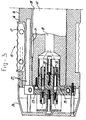
- Figs. 2, 3 and 4 show more particularly the design of the cross seal shafts 12 according to a first variant.
- said shafts have pushed onto them a casing part 14, having on the radial peripheral surface six cross seal tools 15 distributed at equal angular intervals.
- the cross seal tools are integral with the casing part 14.
- each cross seal tool 15 has a central slit 16, for the accommodation of a cutter 17.
- Figs. 3 and 4 show that the shaft 12 is hollow in design.
- Current-conducting wires shown only by dotted lines here, run through the hollow 18. These current-conducting wires run from the housing 13 and are connected to a power source (not shown), for example by means of sliding contacts (not visible) fitted on the shaft 12.
- the hollow 18 is widened at the free end of the shaft 12, for the accommodation of a plug 19.
- Said plug 19 can be connected as a separate part to the shaft 12.
- the current-conducting wires can be connected electrically to the pins 20 of said plug 19.
- Fig. 2 shows that six pins 20 are present.
- the shaft 12 is also provided with a key 21 on the radial outer peripheral surface, the function of which key will emerge more clearly below.
- the casing part 14 has an inner peripheral radius which is slightly smaller or larger than the outer peripheral radius of the shaft 12.
- the casing part 14 has a longitudinal slit 22 running along its entire length, and running over the full wall thickness and permitting a deformation of the casing part in the radial peripheral direction. Since the casing part is made of a steel alloy, and the slit is sufficiently narrow, the deformations of the casing part will be elastic through widening/narrowing of the slit 22.
- a bolt 23 is fitted at both axial ends of the casing part (Fig. 2), in each case acting upon either side of the slit 22.
- the thickened bolt head engages in the casing part 14 at one side of the slit 22, and the threaded part on the shank of the bolt 23 engages in an internally threaded hole in the casing part at the other side of the slit 22.
- the slit 22 can be widened/narrowed by tightening/loosening the bolt 23. Narrowing the slit 22 means that the casing part 14 can be clamped on the shaft 12 on all sides. Widening the slit 22 means that the casing part is easily pushed onto the shaft 12 and removed from it again.
- the adjustment of the inner peripheral radius of the casing part to the outer peripheral radius of the shaft 12 permits clamping of the casing part 14 on the shaft 12 on all sides, through using the slit 22 and the elastic deformability of the casing part 14.
- the use of the casing part 14 requires no special recesses in the radial peripheral surface of the shaft 12, which is advantageous as regards the bending rigidity of the shaft 12, and thus the working accuracy and reliability of the tools 15 on the unilaterally supported shaft 12.
- the casing part 14 is provided with an axial cover 24, for covering the free end face of the shaft 12.
- the cover 24 houses a connector 25 with mating terminals 26, which project into the hollow surrounded by the casing part 14.
- Said mating terminals 26 are intended for plugging into the pins 20 on the plug part 19, which is inserted in the shaft 12 and is connected thereto.
- electrical conductors run from the mating terminals 26. They run to electrical heating elements and measuring elements (not shown in any further detail), which elements are accommodated in hollows 27 in the tools 15 on the casing part 14.
- the connector 25 is simple to change.
- the casing part 14 is also provided on the radial inner peripheral surface with a keyway groove 28 running in the axial direction.
- the key 21 on the shaft 12 engages in the keyway groove 28 in the casing part 14.
- the casing part 14 is consequently secured against rotation relative to the shaft 12.
- the key 21 is positioned as far away as possible from the support of the shaft 12, so that the shaft 12 is weakened as little as possible.
- Fig. 5 shows a variant for the assembly of unilaterally (cantilever) supported shaft 12 and casing part 14 pushed thereon.
- the casing part 14 in this embodiment is closed, i.e. the slit 22 from the variant according to Figs. 2 - 4 is absent here.
- This casing part 14 is consequently not easily radially deformable.
- the radial inner peripheral surface of the casing part is adapted with slight play to the radial outer peripheral surface of the shaft 12, with the exception of an axial end region.
- the shaft 12 there is tapered 29 at the end facing away from the support 13 (Fig. 1), in order to determine an annular gap 31 between the casing part 14 and the shaft 12.
- a sleeve 32 is inserted into said gap 31.
- Said sleeve 32 has at one end a flange for resting against the axial end of the casing part 14.
- the sleeve is hollow, and relatively thin-walled, except in the flange region.
- a fluid such as a hydraulic fluid, is present in said hollow 33.
- a bolt 34 on the flange projects up to the hollow 33. The pressure in the hollow can be adjusted by tightening and loosening said bolt 34.
- the radial peripheral walls of the sleeve 32 will deform in the radial direction through a pressure increase in the hollow 33. If the sleeve 32 is undeformed, i.e.
- the sleeve 32 is dimensioned in such a way that it is easily placed in the gap 31 and easily removed therefrom again.
- an increase in pressure in the hollow 33 will cause the sleeve 32 to expand in the radial direction, so that it is clamped between the radial outer surface of the tapered part 29 of the shaft 12 and the radial inner surface of the casing part 14.
- the casing part 14 is consequently held clamped reliably on all sides on the shaft 12.
- the shaft 12 is not weakened by holes for fixing the tools 15.
- the tapered part 29 is situated on the end of the shaft 12 facing away from the support 13, and thereby hardly reduces the axial dimensional stability of the shaft 12.
- FIG. 5 shows a variant in which the tools 15 are unheated.
- This variant could also be used for heated tools 15 if desired, for example by taking the measures shown in Figs. 2 - 4.
- the principle of a radially expanding sleeve 32 shown in Fig. 5 could also be used if desired for an embodiment of the type shown in Figs. 2 - 4.
- the principle of the longitudinal slit 22 can also be used in connection with unheated tools 15, for example in the embodiment shown in Fig. 5.
- the sleeve 32 can then be omitted.
- a combination of expanding sleeve 32 and longitudinal slit 22 can also be used if desired.
- the casing part can also be devided into several sections, for example it can consist of two shell halves.
- the casing part In connection with the resetting outside the flowpacker, it is, however, preferable for the casing part, that it is assembled beforehand and provided with the tools, to be pushed onto the shaft, and retained thereon.
Landscapes
- Engineering & Computer Science (AREA)
- Mechanical Engineering (AREA)
- Physics & Mathematics (AREA)
- Thermal Sciences (AREA)
- Package Closures (AREA)
- Wrapping Of Specific Fragile Articles (AREA)
- Supplying Of Containers To The Packaging Station (AREA)
- Auxiliary Devices For And Details Of Packaging Control (AREA)
- Containers And Plastic Fillers For Packaging (AREA)
Claims (9)
- Verpackungsvorrichtung (1) zum Verpacken von Gegenständen, die aufeinanderfolgend in einem Strom zugeführt werden, wobei die Vorrichtung folgendes aufweist: ein Förderband (4, 6) zum Fortbewegen der Gegenstände in der Abstromrichtung, eine Vorratsquelle (7) zum Zuführen einer Bahn aus biegsamem folienartigen Packstoff zu dem Förderband, eine Schlauchformeinrichtung (8), um den Packstoff um das Förderband (4, 6) herum zu einem Schlauch zu formen, Schlauchschweißelemente (11), die entlang dem Förderband an der Abstromseite der Schlauchformeinrichtung (8) angeordnet sind, um den Packstoffschlauch in der Längsrichtung zu verschweißen, indem die Längsränder der Bahn, die aufeinandergelegt worden sind, miteinander verbunden werden, und Querschweißelemente (12, 15), die an der Abstromseite der Längsschweißelemente angeordnet sind, um den Schlauch in in Längsrichtung des Schlauchs gesehen beabstandeten Querzonen zusammenzudrücken, wobei der Raum zwischen den zusammengedrückten Zonen einen oder mehrere Gegenstände aus dem Strom enthält, und wobei die Querschweißelemente geeignet sind, um die Wandungen des Schlauchs, die in diesen Querzonen gegeneinander gedrückt worden sind, miteinander zu verbinden, so daß in dem Schlauch eine Querschweißnaht gebildet wird, und die Querschweißelemente fakultativ mit Mitteln (17) versehen sind, um den Schlauch in den Querzonen zu trennen, so daß Einzelpackungen erhalten werden, die mit einem oder mehreren Gegenständen von dem Strom gefüllt sind, wobei die Querschweißelemente (12, 15) mit Schweißelementen (15) versehen sind, die einander gegenüberstehend an beiden Seiten des Förderbands angeordnet sind, wobei die Schweißelemente aufeinander zu und voneinander weg bewegbar sind, um zuzulassen, daß der Schlauch mit den darin befindlichen Gegenständen ungehindert zwischen ihnen durchläuft, und um den Schlauch zwischen sich in den Querzonen zusammenzudrücken, wobei wenigstens eines der Schweißelemente ein Drehelement (12) aufweist, das in bezug auf die Längsrichtung der Förderbands (4, 6) rechtwinklig von einer Drehantriebseinheit vorsteht und das Förderband überlappt, wobei an seinem radialen Umfang wenigstens ein rippenförmiger Vorsprung (15) angeordnet ist und jeder der Vorsprünge die Schweißelemente (15) bildet und die Trennmittel (17) zwischen den Schweißelementen aufnimmt, wobei sowohl die Vorsprünge als auch die Trennmittel im wesentlichen parallel in bezug auf die Längsrichtung des Drehelements verlaufen, um mit dem Schlauch in den Querzonen in Kontakt zu gelangen, wobei die rippenförmigen Vorsprünge (15) mit dem Drehelement (12) unter Zwischenschaltung von Verbindungselementen abnehmbar verbunden sind, und wobei das von der Antriebseinheit weg weisende Ende des Drehelements (12) nicht abgestützt ist, dadurch gekennzeichnet, daß das Drehelement (12) über wenigstens einen Teil der Länge von einem Gehäuseteil (14) umschlossen ist, wobei das Gehäuseteil (14) die rippenförmigen Vorsprünge (15) und die Trennmittel (17) an seinem Außenumfang trägt und das Gehäuseteil (14) an dem Drehelement (12) mittels zusammenwirkender Eingriffsmittel (21, 22, 23, 28, 32, 34) abnehmbar festgelegt ist, um das Gehäuseteil (14) gegen eine Rotation auf dem Drehelement (12) zu sichern.
- Verpackungsvorrichtung (1) nach Anspruch 1, wobei das Gehäuseteil (14) auf dem Drehelement (12) allseitig festgelegt gehalten ist.
- Verpackungsvorrichtung nach Anspruch 1 oder 2, wobei das Gehäuseteil (14) einen Längsspalt (22) und ein oder mehr Elemente (23) hat, die auf beiden Seiten des Spalts wirksam sind, um die Spaltbreite einzustellen.
- Verpackungsvorrichtung nach Anspruch 1 oder 2, wobei zwischen dem Gehäuseteil (14) und dem Drehelement (12) ein Umfangsspalt (31) aufrechterhalten wird und in diesem Spalt (31) ein ringförmiges Festlegeelement (32) aufgenommen ist, wobei das Festlegeelement (32) zwischen dem Gehäuseteil (14) und dem Drehelement (12) unter radialer Kompression gehalten ist.
- Verpackungsvorrichtung (1) nach Anspruch 4, wobei das ringförmige Festlegeelement (32) hohl ist, der hohle Raum (33) mit einem Fluid mit verstellbarem Druck gefüllt ist und die radial innenseitige und/oder außenseitige Wand des ringförmigen Festlegeelements (32) unter der Einwirkung einer Druckänderung in dem Fluid in der Radialrichtung verformbar ist, und wobei das Drehelement (12) in dem Bereich (29) des Elements (12), der von dem ringförmigen Festlegeelement (32) überlappt ist, fakultativ verjüngt ist.
- Verpackungsvorrichtung (1) nach einem der vorhergehenden Ansprüche, wobei die rippenförmigen Vorsprünge (15) und das Gehäuseteil (14) integral sind.
- Verpackungsvorrichtung (1) nach einem der vorhergehenden Ansprüche, wobei das Gehäuseteil (14) ein einteiliges hülsenartiges Element ist, das von dem Ende des Drehelements (12) her, das von der Drehantriebseinheit weg weist, über die Vorrichtung geschoben werden kann.
- Verpackungsvorrichtung (1) nach einem der vorhergehenden Ansprüche, wobei ein oder mehr Stromleiterelemente von der Drehantriebseinheit durch das Drehelement (12) verlaufen und mit einer Stromquelle auf der Seite der Drehantriebseinheit verbunden sind, wobei die Stromleiterelemente mit ersten Verbinderelementen (20), die an der Oberfläche des Drehwellenelements (12) münden, elektrisch gekoppelt sind, wobei jeder der rippenförmigen Vorsprünge (15) ein elektrisches Heizelement hat, mit dem ein Stromleiterelement elektrisch gekoppelt ist, und an dem freien Ende dieses Stromleiterelements ein zweites Verbinderelement (26) angeordnet ist, und wobei die jeweiligen ersten und zweiten Verbinderelemente (20, 26) miteinander lösbar verbunden sind und die ersten Verbinderelemente (20) fakultativ an der Endfläche des Drehelements (12), die von der Drehantriebseinheit weg weist, angeordnet sind.
- Packvorrichtung nach einem der vorhergehenden Ansprüche, wobei das Drehelement (12) und das Gehäuseteil (14) eine zusammenwirkende Einheit aus Keil (21) und Keilnut (28) an der äußeren bzw. der inneren Umfangsoberfläche bilden.
Applications Claiming Priority (2)
| Application Number | Priority Date | Filing Date | Title |
|---|---|---|---|
| NL9400550A NL9400550A (nl) | 1994-04-07 | 1994-04-07 | Flowpacker en beitelsamenstel daarvoor. |
| NL9400550 | 1994-04-07 |
Publications (2)
| Publication Number | Publication Date |
|---|---|
| EP0676331A1 EP0676331A1 (de) | 1995-10-11 |
| EP0676331B1 true EP0676331B1 (de) | 1998-10-21 |
Family
ID=19864038
Family Applications (1)
| Application Number | Title | Priority Date | Filing Date |
|---|---|---|---|
| EP95200696A Expired - Lifetime EP0676331B1 (de) | 1994-04-07 | 1995-03-21 | Vorrichtung zum Verpacken von kontinuierlich zugeführten Gegenständen und Werkzeug dazu |
Country Status (6)
| Country | Link |
|---|---|
| US (1) | US5548946A (de) |
| EP (1) | EP0676331B1 (de) |
| AT (1) | ATE172419T1 (de) |
| BR (1) | BR9501471A (de) |
| DE (1) | DE69505445T2 (de) |
| NL (1) | NL9400550A (de) |
Families Citing this family (26)
| Publication number | Priority date | Publication date | Assignee | Title |
|---|---|---|---|---|
| IT1279674B1 (it) * | 1995-11-07 | 1997-12-16 | Azionaria Costruzioni Acma Spa | Metodo ed apparecchiatura per la saldatura di un film di materiale per incarto. |
| US5979148A (en) * | 1996-12-04 | 1999-11-09 | Privatizer Systems, Inc. | Apparatus and method for sealing an envelope in a document security apparatus having a sealing roller with a sealing ridge attached thereto |
| DE19744416C1 (de) * | 1997-10-08 | 1999-02-04 | Iwk Verpackungstechnik Gmbh | Fördervorrichtung in einer Verpackungsmaschine |
| US6481188B1 (en) | 2000-06-30 | 2002-11-19 | Owens Corning Fiberglas Technology, Inc. | Apparatus and method for sealing an article |
| US20040076778A1 (en) * | 2001-02-05 | 2004-04-22 | Hirotsugu Mori | Biodegradable bags for packing foods available in high speed production |
| US6574944B2 (en) * | 2001-06-19 | 2003-06-10 | Mars Incorporated | Method and system for ultrasonic sealing of food product packaging |
| US6625853B2 (en) * | 2001-09-17 | 2003-09-30 | Sca Hygiene Products Ab | Method of compressing fibrous bodies |
| ITVR20020106A1 (it) * | 2002-10-25 | 2004-04-26 | Bg Pack S P A | Macchina confezionatrice orizzontale per la realizzazione |
| DE10261256B4 (de) * | 2002-12-20 | 2004-11-11 | Windmöller & Hölscher Kg | Bodenlegevorrichtung |
| US8261518B2 (en) * | 2005-07-22 | 2012-09-11 | Pitney Bowes Inc. | In-line deformation binding apparatus |
| KR100991459B1 (ko) * | 2008-06-16 | 2010-11-04 | 탑와이어 주식회사 | 제본용 스프링 포장장치 |
| US8087220B2 (en) | 2009-04-21 | 2012-01-03 | Extreme Packaging Machinery, Inc. | Film sealing and wrapping machine with rotary cut and seal jaw |
| US20110005173A1 (en) * | 2009-07-08 | 2011-01-13 | Kraft Foods Global Brands Llc | Method and Apparatus to Create a Contoured Flow Wrap Package |
| JP5476107B2 (ja) * | 2009-12-07 | 2014-04-23 | 株式会社イシダ | 製袋包装機 |
| DE102012204196A1 (de) | 2012-03-16 | 2013-09-19 | Robert Bosch Gmbh | Horizontalquersiegeleinheit |
| WO2017065791A1 (en) | 2015-10-16 | 2017-04-20 | Avent, Inc. | Method and system for placing pre-cut nose wires in a facemask manufacturing process |
| MX381816B (es) | 2015-10-16 | 2025-03-13 | O&M Halyard Int Unlimited Co | Método y sistema para apilado y carga automatizados de mascarillas envueltas en una caja de cartón en una línea de fabricación. |
| MX2018004353A (es) | 2015-10-16 | 2018-05-22 | Avent Inc | Metodo y sistema para empalmar tiras metalicas adaptables en un proceso de fabricacion de mascarillas. |
| AU2015411837A1 (en) | 2015-10-16 | 2018-04-19 | O&M Halyard International Unlimited Company | Method and system for automated stacking and loading wrapped facemasks into a carton in a manufacturing line |
| US20180208343A1 (en) * | 2015-10-16 | 2018-07-26 | Avent, Inc. | Method and System for Wrapping and Preparing Facemasks for Packaging in a Manufacturing Line |
| MX379643B (es) | 2015-10-16 | 2025-03-11 | O&M Halyard Int Unlimited Co | Metodo y sistema para cortar y colocar tiras metalicas adaptables en un proceso de fabricacion de mascarillas. |
| EP3932811B8 (de) * | 2020-06-29 | 2022-07-20 | Ulma Packaging, S.Coop. | Waagerechte verpackungsmaschine |
| IT202000019420A1 (it) * | 2020-08-06 | 2022-02-06 | Tecno Pack S P A | Macchina confezionatrice orizzontale con gruppo taglia-cuci regolabile |
| IT202000019414A1 (it) * | 2020-08-06 | 2022-02-06 | Tecno Pack S P A | Macchina confezionatrice orizzontale con gruppo taglia-cuci regolabile |
| CN114920012B (zh) * | 2022-05-30 | 2023-11-21 | 重庆桥头食品有限公司 | 一种老火锅自动化生产及运输系统 |
| US20250382081A1 (en) * | 2024-06-14 | 2025-12-18 | The Procter & Gamble Company | Polymer film envelope package for compact feminine hygiene pad product, and process and tooling for manufacture thereof |
Family Cites Families (15)
| Publication number | Priority date | Publication date | Assignee | Title |
|---|---|---|---|---|
| FR828967A (fr) * | 1937-02-10 | 1938-06-07 | Bouchons pour bouteilles et analogues | |
| US3086577A (en) * | 1960-03-09 | 1963-04-23 | David C Gimple | Garment bag making equipment |
| FR1260892A (fr) * | 1960-06-02 | 1961-05-12 | Procter & Gamble | Machine à empaqueter du type rotatif |
| NL274656A (de) * | 1961-02-16 | |||
| GB1114501A (en) * | 1964-08-14 | 1968-05-22 | Ind Developments Packaging Ltd | Improvements in or relaing to heat sealing of plastics film |
| US3439471A (en) * | 1966-05-17 | 1969-04-22 | Nat Dairy Prod Corp | Packaging apparatus |
| US3605194A (en) * | 1968-02-01 | 1971-09-20 | Rowland Products Inc | Resiliently faced rolls |
| CH507786A (de) * | 1969-05-06 | 1971-05-31 | Sig Schweiz Industrieges | Schneidvorrichtung mit rotierendem Zick-Zack-Messer |
| US3616095A (en) * | 1969-11-06 | 1971-10-26 | Hercules Membrino | Apparatus for forming a strip of severable bags from thermoplastic material |
| US3850780A (en) * | 1971-08-23 | 1974-11-26 | Fmc Corp | Extended dwell heat sealer |
| US3943686A (en) * | 1974-09-05 | 1976-03-16 | Fmc Corporation | Wrapping machine with severing blade in crimping head |
| US4574566A (en) * | 1985-01-14 | 1986-03-11 | Doboy Packaging Machinery, Inc. | Wrapping machine and method |
| US4807426A (en) * | 1987-09-08 | 1989-02-28 | Smith Larry E | Crimper bar set for forming hermetically sealed packages |
| US4949846A (en) * | 1989-07-31 | 1990-08-21 | Lakey Lawrence D | Package end sealing and cutting method and apparatus |
| US5094657A (en) * | 1990-11-29 | 1992-03-10 | Cloud Corporation | Method and apparatus for continuously forming and sealing low density polyethylene bags at high speed |
-
1994
- 1994-04-07 NL NL9400550A patent/NL9400550A/nl not_active Application Discontinuation
-
1995
- 1995-03-21 DE DE69505445T patent/DE69505445T2/de not_active Expired - Fee Related
- 1995-03-21 EP EP95200696A patent/EP0676331B1/de not_active Expired - Lifetime
- 1995-03-21 AT AT95200696T patent/ATE172419T1/de not_active IP Right Cessation
- 1995-03-31 US US08/414,295 patent/US5548946A/en not_active Expired - Fee Related
- 1995-04-06 BR BR9501471A patent/BR9501471A/pt unknown
Also Published As
| Publication number | Publication date |
|---|---|
| NL9400550A (nl) | 1995-11-01 |
| ATE172419T1 (de) | 1998-11-15 |
| US5548946A (en) | 1996-08-27 |
| DE69505445T2 (de) | 1999-05-27 |
| EP0676331A1 (de) | 1995-10-11 |
| BR9501471A (pt) | 1995-11-07 |
| DE69505445D1 (de) | 1998-11-26 |
Similar Documents
| Publication | Publication Date | Title |
|---|---|---|
| EP0676331B1 (de) | Vorrichtung zum Verpacken von kontinuierlich zugeführten Gegenständen und Werkzeug dazu | |
| US7941991B2 (en) | Split crimper for heat sealing packaging material | |
| EP1100658B1 (de) | Rotierende schneid- und/oder schweissvorrichtung | |
| EP1919692B1 (de) | Anordnung zum ultraschallversiegeln von röhrenförmigen endlosstreifen | |
| EP0098024B1 (de) | Verfahren zum Verbinden vorgefertigter wärmeisolierter Rohre und schweissbares Passstück dafür | |
| US5851121A (en) | Miniature shielded connector with elbow contact shafts | |
| KR100935043B1 (ko) | 초음파 용접 장치와, 초음파 용접 장치에 회전식 초음파 용접 혼을 장착하기 위한 방법 | |
| US5085535A (en) | Locating mechanism | |
| EP2922668B2 (de) | Dichtungs- und schneideinheit für eine formfüllungs- und dichtmaschine | |
| JPS622908B2 (de) | ||
| GB2096797A (en) | Positioning tooling devices relative to a battery | |
| AU7068300A (en) | Seal jaw modules for reclose bag modification to vertical form, fill, and seal packaging system | |
| DE2353886B2 (de) | Vorrichtung zum kontinuierlichen herstellen von beuteln aus einer laengsgefalteten, thermoplastischen oder heisssiegelfaehigen bahn | |
| KR920002308B1 (ko) | 방전 공작 기계 | |
| US20250183745A1 (en) | Stator, apparatus and method for peparing a pre-shaped insulator | |
| CA1262932A (en) | Gas-cooled rotor winding assembly | |
| KR100597334B1 (ko) | 캡슐 | |
| EP0402336A2 (de) | Strangpressdüse | |
| JPH05112333A (ja) | 包装容器の熱接着部形成用加熱ロール装置 | |
| JPH0215277Y2 (de) | ||
| EP0729666A1 (de) | Verfahren zur herstellung eines stators für eine rotierende elektrische maschine | |
| JPS5933192Y2 (ja) | 圧着電気接続具帯の搬送供給装置 | |
| EP0725762B1 (de) | Methode zur trennung von metallen und alkoholen von einem emulgierten organischen/wässrigen abwasser | |
| JP2003170916A (ja) | ヒートシール装置 | |
| DE2835671A1 (de) | Schweissmaschine fuer thermoplastische folien |
Legal Events
| Date | Code | Title | Description |
|---|---|---|---|
| PUAI | Public reference made under article 153(3) epc to a published international application that has entered the european phase |
Free format text: ORIGINAL CODE: 0009012 |
|
| AK | Designated contracting states |
Kind code of ref document: A1 Designated state(s): AT CH DE FR GB IT LI NL |
|
| 17P | Request for examination filed |
Effective date: 19950927 |
|
| 17Q | First examination report despatched |
Effective date: 19970124 |
|
| GRAG | Despatch of communication of intention to grant |
Free format text: ORIGINAL CODE: EPIDOS AGRA |
|
| GRAG | Despatch of communication of intention to grant |
Free format text: ORIGINAL CODE: EPIDOS AGRA |
|
| GRAH | Despatch of communication of intention to grant a patent |
Free format text: ORIGINAL CODE: EPIDOS IGRA |
|
| GRAH | Despatch of communication of intention to grant a patent |
Free format text: ORIGINAL CODE: EPIDOS IGRA |
|
| GRAA | (expected) grant |
Free format text: ORIGINAL CODE: 0009210 |
|
| AK | Designated contracting states |
Kind code of ref document: B1 Designated state(s): AT CH DE FR GB IT LI NL |
|
| PG25 | Lapsed in a contracting state [announced via postgrant information from national office to epo] |
Ref country code: AT Free format text: LAPSE BECAUSE OF FAILURE TO SUBMIT A TRANSLATION OF THE DESCRIPTION OR TO PAY THE FEE WITHIN THE PRESCRIBED TIME-LIMIT Effective date: 19981021 |
|
| REF | Corresponds to: |
Ref document number: 172419 Country of ref document: AT Date of ref document: 19981115 Kind code of ref document: T |
|
| REG | Reference to a national code |
Ref country code: CH Ref legal event code: EP |
|
| REF | Corresponds to: |
Ref document number: 69505445 Country of ref document: DE Date of ref document: 19981126 |
|
| REG | Reference to a national code |
Ref country code: CH Ref legal event code: NV Representative=s name: R. A. EGLI & CO. PATENTANWAELTE |
|
| ET | Fr: translation filed | ||
| PLBE | No opposition filed within time limit |
Free format text: ORIGINAL CODE: 0009261 |
|
| STAA | Information on the status of an ep patent application or granted ep patent |
Free format text: STATUS: NO OPPOSITION FILED WITHIN TIME LIMIT |
|
| 26N | No opposition filed | ||
| REG | Reference to a national code |
Ref country code: GB Ref legal event code: IF02 |
|
| PGFP | Annual fee paid to national office [announced via postgrant information from national office to epo] |
Ref country code: NL Payment date: 20050131 Year of fee payment: 11 |
|
| PGFP | Annual fee paid to national office [announced via postgrant information from national office to epo] |
Ref country code: GB Payment date: 20050225 Year of fee payment: 11 |
|
| PGFP | Annual fee paid to national office [announced via postgrant information from national office to epo] |
Ref country code: FR Payment date: 20050316 Year of fee payment: 11 |
|
| PGFP | Annual fee paid to national office [announced via postgrant information from national office to epo] |
Ref country code: CH Payment date: 20050321 Year of fee payment: 11 |
|
| PGFP | Annual fee paid to national office [announced via postgrant information from national office to epo] |
Ref country code: DE Payment date: 20050324 Year of fee payment: 11 |
|
| PG25 | Lapsed in a contracting state [announced via postgrant information from national office to epo] |
Ref country code: GB Free format text: LAPSE BECAUSE OF NON-PAYMENT OF DUE FEES Effective date: 20060321 |
|
| PG25 | Lapsed in a contracting state [announced via postgrant information from national office to epo] |
Ref country code: LI Free format text: LAPSE BECAUSE OF NON-PAYMENT OF DUE FEES Effective date: 20060331 Ref country code: CH Free format text: LAPSE BECAUSE OF NON-PAYMENT OF DUE FEES Effective date: 20060331 |
|
| PGFP | Annual fee paid to national office [announced via postgrant information from national office to epo] |
Ref country code: IT Payment date: 20060331 Year of fee payment: 12 |
|
| PG25 | Lapsed in a contracting state [announced via postgrant information from national office to epo] |
Ref country code: NL Free format text: LAPSE BECAUSE OF NON-PAYMENT OF DUE FEES Effective date: 20061001 |
|
| PG25 | Lapsed in a contracting state [announced via postgrant information from national office to epo] |
Ref country code: DE Free format text: LAPSE BECAUSE OF NON-PAYMENT OF DUE FEES Effective date: 20061003 |
|
| REG | Reference to a national code |
Ref country code: CH Ref legal event code: PL |
|
| GBPC | Gb: european patent ceased through non-payment of renewal fee |
Effective date: 20060321 |
|
| NLV4 | Nl: lapsed or anulled due to non-payment of the annual fee |
Effective date: 20061001 |
|
| REG | Reference to a national code |
Ref country code: FR Ref legal event code: ST Effective date: 20061130 |
|
| PG25 | Lapsed in a contracting state [announced via postgrant information from national office to epo] |
Ref country code: FR Free format text: LAPSE BECAUSE OF NON-PAYMENT OF DUE FEES Effective date: 20060331 |
|
| PG25 | Lapsed in a contracting state [announced via postgrant information from national office to epo] |
Ref country code: IT Free format text: LAPSE BECAUSE OF NON-PAYMENT OF DUE FEES Effective date: 20070321 |