EP0675509A2 - Isolateurs composites et un procédé pour les fabriquer - Google Patents
Isolateurs composites et un procédé pour les fabriquer Download PDFInfo
- Publication number
- EP0675509A2 EP0675509A2 EP95302045A EP95302045A EP0675509A2 EP 0675509 A2 EP0675509 A2 EP 0675509A2 EP 95302045 A EP95302045 A EP 95302045A EP 95302045 A EP95302045 A EP 95302045A EP 0675509 A2 EP0675509 A2 EP 0675509A2
- Authority
- EP
- European Patent Office
- Prior art keywords
- rod
- around
- outer periphery
- insulating material
- insulating
- Prior art date
- Legal status (The legal status is an assumption and is not a legal conclusion. Google has not performed a legal analysis and makes no representation as to the accuracy of the status listed.)
- Granted
Links
Images


Classifications
-
- H—ELECTRICITY
- H01—ELECTRIC ELEMENTS
- H01B—CABLES; CONDUCTORS; INSULATORS; SELECTION OF MATERIALS FOR THEIR CONDUCTIVE, INSULATING OR DIELECTRIC PROPERTIES
- H01B17/00—Insulators or insulating bodies characterised by their form
- H01B17/02—Suspension insulators; Strain insulators
- H01B17/12—Special features of strain insulators
-
- H—ELECTRICITY
- H01—ELECTRIC ELEMENTS
- H01B—CABLES; CONDUCTORS; INSULATORS; SELECTION OF MATERIALS FOR THEIR CONDUCTIVE, INSULATING OR DIELECTRIC PROPERTIES
- H01B17/00—Insulators or insulating bodies characterised by their form
- H01B17/38—Fittings, e.g. caps; Fastenings therefor
- H01B17/40—Cementless fittings
Definitions
- the present invention relates to composite insulators each formed by molding an elastic insulating material around an insulating rod having a end fitting connected to each of opposite ends thereof.
- the invention also relates to a process for producing the same.
- the composite insulator includes an insulating rod 51 made of glass fiber-reinforced plastic (FRP) or the like, end fittings 54 crimped to opposite end portions of the insulating rod 51, respectively, and an elastic insulating material 53 molded around the outer periphery of the insulating rod 51.
- FRP glass fiber-reinforced plastic
- a plurality of shed portions 52a are integrally formed with sheath portions 52b from the insulating material 53.
- Each of the end fitting grasps an end portion of the elastic insulating material 53.
- the reason why the electric characteristic of the composite insulator does not satisfy the reference value is that since the effective insulating length between the end fittings 54 is narrowed by themselves, an insulating effective insulating length cannot be sufficiently ensured.
- the effective insulating length between the end fittings 54 may be increased by increasing the the entire length of the insulating rod 51 and the molded elastic insulating material 53.
- the term "effective insulating length" used therein means a longitudinal space between both the end fitting.
- the entire length of the rod 51 that is, the entire length of the composite insulator consequently increases, such an insulator cannot be used in the electric power transmission system in which the entire length of the insulator to be employed is preliminarily determined.
- the present invention has been accomplished to solve the above-mentioned problem, and a first object of the present invention is to provide a composite insulator which has enhanced insulation tolerance and maintains strength by increasing the effective insulating length without increasing the entire length of the insulator.
- a second object of the present invention is to provide a composite insulator in which an insulating material is molded around an insulating rod and end fittings without leaking the insulating material outside.
- a third object of the present invention is to provide a process for producing such composite insulators.
- the composite insulator according to the present invention comprises an insulating rod, end fittings crimped to opposite end portions of said insulating rod, and an elastic insulating material molded around the outer periphery of the insulating rod, wherein each of said end fittings has a flange around the outer periphery of a end fitting body on an axially external side thereof, and said elastic insulating material is molded around the outer periphery of the insulating rod and those of the end fitting bodies such that the elastic material extends up to and between the flanges.
- the effective insulating length of the insulator can be increased without increasing the entire length of the insulator. Further, leakage of the elastic insulating material during the molding thereof can be prevented by the flange of the end fitting. In addition, sealing is effected, with the elastic insulating material, between the rod and a peripheral surface of a hole of the end fitting into which an end of the rod is inserted.
- the process for producing the composite insulator according to the present invention which composite insulator comprises an insulating rod, end fittings around opposite end portions of said insulating rod, and an elastic insulating material around the outer periphery of the insulating rod, each of said end fittings having an axial hole therein and a flange around the outer periphery of a end fitting body on an axially external side thereof, said process comprising the steps of:
- a metallic end fitting 2 plated with zinc is connected to each of opposite end portions of a cylindrical insulating rod 1 made of FRP by crimping a cylindrical barrel portion 3 of the end fitting 2.
- the end fitting 2 includes the barrel portion 3 in which a blind-hole is provided for receiving the end portion of the insulating rod 1, a joint portion 5 at an axially outer side, and a flange portion 6 formed, at an outer end portion, integrally with the joint portion 5 and the barrel portion 3 and radially outwardly extending.
- a hole through which a bolt not shown is passed.
- the end metallic fitting may be made of forged steel, ductile iron, malleable iron, aluminum, or the like.
- an elastic insulating material 8 made of silicon rubber, ethylene-propylene rubber or the like.
- the elastic insulating material 8 includes a plurality of shed portions 8a and sheath portions 8b, 8b' connecting the adjacent shed portions 8a or positioned axially outwardly from the axially outermost shed portions.
- the thickness t1 of the elastic insulating material 8 molded around the outer periphery of the barrel portion of the end fitting is made greater than that t2 of the elastic insulating material 8 around the rod 1 by about 30 % to about 40 %.
- the thickness t3 of the insulating material 8 around the outer periphery of the rod 1 near the barrel portion 3 is greater than that t2 of the insulating material 8 around the outer periphery of a middle portion of the rod 1, and the length t4 of the thickened portion at t3 is greater than the thickness t3.
- the end fitting 2 is surrounded with a thicker portion of the elastic insulating material 8 as compared with the rod 1.
- the outer periphery of the flange 6 is continued to and flush with the outer peripheral surface of the sheath portion 8b' of the elastic insulating material 8 so that the flange 6 may not radially outwardly extend beyond the sheath portion 8b' of the elastic insulating member 8.
- the radially outermost shed portion 8a is located near but axially inwardly from the flange 6.
- an inner peripheral surface of the rod-inserting hole 7 in the metallic end fitting 2 plated with melted zinc is roughed by removing a plated layer at the inner peripheral surface of the hole 7 with using a boring tool or the like. Then, the rod 1 is inserted into the hole 7, and the barrel portion 3 of the end fitting 2 is crimping to the outer periphery of the rod 1.
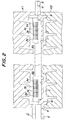
- crimping is effected first at a crimping position 3a at an axially inner tip side of the barrel portion in Fig. 2. Crimping is further effected in the order of crimping positions 3b, 3c and 3d, following 3a.
- the crimping is effected at the crimping positions 3a through 3d under different crimping forces or pressure by which the barrel portion 3 is crimped. That is, the crimping pressure is 128 kgf/cm2 at the crimping position 3a, 150 kgf/cm2 at the crimping position 3b, 164 kgf/cm2 at the crimping position 3c, and 164 kgf/cm2 at the crimping position 3d. That is, the crimping pressure is set greater as the crimping position approaches the axially outer side of the rod.
- crimping is preferably effected in the state that the adjacent crimping locations partially overlap. In other words, it is preferable that the crimping force decreases as the crimping location approaches the open edge portion of the end fitting, so that high pressure is prevented from being applied to the insulating rod at the open edge portion of the end fitting.
- the elastic insulating material 8 is molded.
- the rod 1 and the barrel portions 3 of the end fittings 2 are placed inside a cavity Ka defined between mold units K1 and K2.
- the elastic insulating material such as silicone rubber, ethylene propylene rubber or the like is charged in a melted state into the cavity around the rod and the barrel portions of the end fittings.
- the cavity Ka is heated at a given temperature (150°C ⁇ 180°C) for, e.g., 10 minutes to effect vulcanization.
- the elastic insulating material 8 is cured and molded around the rod 1 and the barrel portions 3 of the end fittings 2.
- the elastic insulating material 8 is molded around all the above-mentioned crimping positions 3a through 3d, while the elastic insulating material extends up to the flanges 6 of the end fittings 2 and is flush with the outer peripheral surface of the flange 6.
- the composite insulator is constituted above in this embodiment, the following effects can be obtained.
- the crimping area of the end fitting is divided into plural zones along the axial direction of the rod 1 and the crimping is effected at such plural zones under application of different crimping pressures. Accordingly, reduction in the end force of the end fitting 2 due to the heat history of the rod on molding the elastic insulating material 8 can be suppressed.
Landscapes
- Insulators (AREA)
Applications Claiming Priority (2)
| Application Number | Priority Date | Filing Date | Title |
|---|---|---|---|
| JP57616/94 | 1994-03-28 | ||
| JP6057616A JP2723468B2 (ja) | 1994-03-28 | 1994-03-28 | ポリマー碍子 |
Publications (3)
| Publication Number | Publication Date |
|---|---|
| EP0675509A2 true EP0675509A2 (fr) | 1995-10-04 |
| EP0675509A3 EP0675509A3 (fr) | 1995-12-20 |
| EP0675509B1 EP0675509B1 (fr) | 1998-07-22 |
Family
ID=13060817
Family Applications (1)
| Application Number | Title | Priority Date | Filing Date |
|---|---|---|---|
| EP95302045A Expired - Lifetime EP0675509B1 (fr) | 1994-03-28 | 1995-03-27 | Isolateurs composites et un procédé pour les fabriquer |
Country Status (5)
| Country | Link |
|---|---|
| US (1) | US6307157B1 (fr) |
| EP (1) | EP0675509B1 (fr) |
| JP (1) | JP2723468B2 (fr) |
| CA (1) | CA2145619C (fr) |
| DE (1) | DE69503545T2 (fr) |
Cited By (2)
| Publication number | Priority date | Publication date | Assignee | Title |
|---|---|---|---|---|
| EP0859376A2 (fr) * | 1997-02-13 | 1998-08-19 | Ngk Insulators, Ltd. | Isolateur polymère |
| FR2761517A1 (fr) * | 1997-03-25 | 1998-10-02 | Ngk Insulators Ltd | Procede de fixation d'un isolateur en polymere et matrice utilisee pour ce procede |
Families Citing this family (14)
| Publication number | Priority date | Publication date | Assignee | Title |
|---|---|---|---|---|
| CA2254099C (fr) * | 1997-03-11 | 2004-04-20 | Ngk Insulators, Ltd. | Procede de fabrication d'un isolant composite et d'un element de garnissage associe |
| JP4601791B2 (ja) * | 2000-09-14 | 2010-12-22 | 株式会社ダイヘン | 樹脂ブッシング |
| JP2002157932A (ja) * | 2000-11-21 | 2002-05-31 | Furukawa Electric Co Ltd:The | 有機複合碍管およびその製造方法 |
| CA2349253C (fr) * | 2000-12-26 | 2009-11-17 | S&C Electric Company | Methode et agencement pour la fourniture d'un joint de boitier etanche aux gaz |
| ATE521070T1 (de) * | 2007-05-23 | 2011-09-15 | Abb Technology Ag | Hochspannungsisolator und kühlelement mit diesem hochspannungsisolator |
| CN101159186B (zh) * | 2007-11-12 | 2010-12-15 | 中国西电电气股份有限公司 | 高压空心复合绝缘子高压端一次封胶方法 |
| JP2012248525A (ja) * | 2011-05-31 | 2012-12-13 | Tokyo Electric Power Co Inc:The | ポリマーがいし |
| US20150380132A1 (en) * | 2013-02-20 | 2015-12-31 | Afl Telecommunications Llc | Manufacturing process and apparatus for crimping and/or swaging strain insulators |
| CN103971861A (zh) * | 2014-05-21 | 2014-08-06 | 北京铁道工程机电技术研究所有限公司 | 一种具有防界面击穿的动车车顶复合绝缘子 |
| CN103971862B (zh) * | 2014-05-21 | 2017-08-01 | 北京铁道工程机电技术研究所有限公司 | 一种动车车顶抗污闪复合绝缘子 |
| CN109003757B (zh) * | 2018-08-07 | 2023-09-12 | 重庆科技学院 | 一种复合绝缘子的压接结构 |
| CN110718343B (zh) * | 2019-10-18 | 2020-11-06 | 江西正强电瓷电器有限公司 | 一种氧化铝瓷芯棒复合绝缘子及其制作方法 |
| US11581111B2 (en) | 2020-08-20 | 2023-02-14 | Te Connectivity Solutions Gmbh | Composite polymer insulators and methods for forming same |
| CN114724789B (zh) * | 2022-03-30 | 2023-08-01 | 南京电气(集团)高新材料有限公司 | 一种用于绝缘子与法兰装配的压接装置 |
Citations (3)
| Publication number | Priority date | Publication date | Assignee | Title |
|---|---|---|---|---|
| CH491474A (de) * | 1968-07-13 | 1970-05-31 | Siemens Ag | Elektrischer Isolierkörper und Verfahren zu dessen Herstellung |
| DE1932949A1 (de) * | 1969-06-28 | 1971-01-07 | Bbc Brown Boveri & Cie | Hochspannungs-Verbundisolator |
| EP0439411A1 (fr) * | 1990-01-26 | 1991-07-31 | Société Nouvelle des Etablissements Dervaux, S.A. | Isolateur composite et son procédé de fabrication |
Family Cites Families (5)
| Publication number | Priority date | Publication date | Assignee | Title |
|---|---|---|---|---|
| US3898372A (en) * | 1974-02-11 | 1975-08-05 | Ohio Brass Co | Insulator with resin-bonded fiber rod and elastomeric weathersheds, and method of making same |
| US4045604A (en) * | 1974-10-08 | 1977-08-30 | Raychem Limited | Recoverable article with outwardly extending hollow heat flanges; kit including such article and a cylindrical substrate; and method of making such article |
| CH589347A5 (fr) * | 1974-12-05 | 1977-06-30 | Cossonay Cableries Trefileries | |
| FR2511180A1 (fr) * | 1981-08-05 | 1983-02-11 | Ceraver | Element isolant electrique comportant un groupe monobloc d'ailettes |
| US5043838A (en) * | 1989-03-31 | 1991-08-27 | Hubbell Incorporated | Modular electrical assemblies with pressure relief |
-
1994
- 1994-03-28 JP JP6057616A patent/JP2723468B2/ja not_active Expired - Lifetime
-
1995
- 1995-03-20 US US08/406,392 patent/US6307157B1/en not_active Expired - Lifetime
- 1995-03-27 EP EP95302045A patent/EP0675509B1/fr not_active Expired - Lifetime
- 1995-03-27 CA CA002145619A patent/CA2145619C/fr not_active Expired - Lifetime
- 1995-03-27 DE DE69503545T patent/DE69503545T2/de not_active Expired - Lifetime
Patent Citations (3)
| Publication number | Priority date | Publication date | Assignee | Title |
|---|---|---|---|---|
| CH491474A (de) * | 1968-07-13 | 1970-05-31 | Siemens Ag | Elektrischer Isolierkörper und Verfahren zu dessen Herstellung |
| DE1932949A1 (de) * | 1969-06-28 | 1971-01-07 | Bbc Brown Boveri & Cie | Hochspannungs-Verbundisolator |
| EP0439411A1 (fr) * | 1990-01-26 | 1991-07-31 | Société Nouvelle des Etablissements Dervaux, S.A. | Isolateur composite et son procédé de fabrication |
Cited By (3)
| Publication number | Priority date | Publication date | Assignee | Title |
|---|---|---|---|---|
| EP0859376A2 (fr) * | 1997-02-13 | 1998-08-19 | Ngk Insulators, Ltd. | Isolateur polymère |
| EP0859376A3 (fr) * | 1997-02-13 | 1999-02-03 | Ngk Insulators, Ltd. | Isolateur polymère |
| FR2761517A1 (fr) * | 1997-03-25 | 1998-10-02 | Ngk Insulators Ltd | Procede de fixation d'un isolateur en polymere et matrice utilisee pour ce procede |
Also Published As
| Publication number | Publication date |
|---|---|
| JP2723468B2 (ja) | 1998-03-09 |
| JPH07272558A (ja) | 1995-10-20 |
| EP0675509A3 (fr) | 1995-12-20 |
| DE69503545D1 (de) | 1998-08-27 |
| CA2145619A1 (fr) | 1995-09-29 |
| US6307157B1 (en) | 2001-10-23 |
| EP0675509B1 (fr) | 1998-07-22 |
| CA2145619C (fr) | 1998-08-25 |
| DE69503545T2 (de) | 1999-01-21 |
Similar Documents
| Publication | Publication Date | Title |
|---|---|---|
| EP0675509B1 (fr) | Isolateurs composites et un procédé pour les fabriquer | |
| EP0617433B1 (fr) | Isolateur électrique composite | |
| EP0093524A2 (fr) | Presse-étoupes pour câble électrique | |
| US6065207A (en) | Composite insulators and a process for producing the same | |
| US5901987A (en) | Method of making an endpiece, an endpiece and a connector made by the method, and a circuit including such a connector | |
| JPH0475604B2 (fr) | ||
| KR910001321B1 (ko) | 주조된 고전압 접속체 및 그 제조방법 | |
| WO2009051721A1 (fr) | Ensembles d'étanchéité et de blindage d'isolateur intégré | |
| JPS6255367B2 (fr) | ||
| EP3304665B1 (fr) | Ensemble joint rigide | |
| EP1489312B1 (fr) | Structure de fixation adaptes a utiliser a basses temperatures | |
| EP1043734B1 (fr) | Isolateur composite électrique, sa méthode d'assemblage et sa méthode de fabrication | |
| US5017161A (en) | Electric terminal connector | |
| US5914462A (en) | Composite insulator having end fittings with gaps | |
| CN210350763U (zh) | 电缆接头对接冷缩管 | |
| US4126498A (en) | Boots for wire rope terminations | |
| US4623213A (en) | Method for joining two aluminum conductors of electric cables and the joint thus obtained | |
| US11581111B2 (en) | Composite polymer insulators and methods for forming same | |
| JP2723468C (fr) | ||
| JP2001084854A (ja) | ポリマー碍子とその製造方法 | |
| JPH06233439A (ja) | ゴムモールド一体形ケーブルヘッド | |
| JP2000295752A (ja) | 絶縁筒およびケーブル接続部の形成方法 | |
| CS269490B1 (cs) | Izolační spoj |
Legal Events
| Date | Code | Title | Description |
|---|---|---|---|
| PUAI | Public reference made under article 153(3) epc to a published international application that has entered the european phase |
Free format text: ORIGINAL CODE: 0009012 |
|
| AK | Designated contracting states |
Kind code of ref document: A2 Designated state(s): DE FR GB |
|
| PUAL | Search report despatched |
Free format text: ORIGINAL CODE: 0009013 |
|
| AK | Designated contracting states |
Kind code of ref document: A3 Designated state(s): DE FR GB |
|
| 17P | Request for examination filed |
Effective date: 19960108 |
|
| 17Q | First examination report despatched |
Effective date: 19960219 |
|
| GRAG | Despatch of communication of intention to grant |
Free format text: ORIGINAL CODE: EPIDOS AGRA |
|
| GRAG | Despatch of communication of intention to grant |
Free format text: ORIGINAL CODE: EPIDOS AGRA |
|
| GRAH | Despatch of communication of intention to grant a patent |
Free format text: ORIGINAL CODE: EPIDOS IGRA |
|
| GRAH | Despatch of communication of intention to grant a patent |
Free format text: ORIGINAL CODE: EPIDOS IGRA |
|
| GRAA | (expected) grant |
Free format text: ORIGINAL CODE: 0009210 |
|
| AK | Designated contracting states |
Kind code of ref document: B1 Designated state(s): DE FR GB |
|
| REF | Corresponds to: |
Ref document number: 69503545 Country of ref document: DE Date of ref document: 19980827 |
|
| ET | Fr: translation filed | ||
| PLBE | No opposition filed within time limit |
Free format text: ORIGINAL CODE: 0009261 |
|
| STAA | Information on the status of an ep patent application or granted ep patent |
Free format text: STATUS: NO OPPOSITION FILED WITHIN TIME LIMIT |
|
| 26N | No opposition filed | ||
| REG | Reference to a national code |
Ref country code: GB Ref legal event code: IF02 |
|
| PGFP | Annual fee paid to national office [announced via postgrant information from national office to epo] |
Ref country code: GB Payment date: 20050317 Year of fee payment: 11 |
|
| PG25 | Lapsed in a contracting state [announced via postgrant information from national office to epo] |
Ref country code: GB Free format text: LAPSE BECAUSE OF NON-PAYMENT OF DUE FEES Effective date: 20060327 |
|
| GBPC | Gb: european patent ceased through non-payment of renewal fee |
Effective date: 20060327 |
|
| PGFP | Annual fee paid to national office [announced via postgrant information from national office to epo] |
Ref country code: FR Payment date: 20140311 Year of fee payment: 20 |
|
| PGFP | Annual fee paid to national office [announced via postgrant information from national office to epo] |
Ref country code: DE Payment date: 20140417 Year of fee payment: 20 |
|
| REG | Reference to a national code |
Ref country code: DE Ref legal event code: R071 Ref document number: 69503545 Country of ref document: DE |