EP0675509A2 - Composite insulators and a process for producing the same - Google Patents
Composite insulators and a process for producing the same Download PDFInfo
- Publication number
- EP0675509A2 EP0675509A2 EP95302045A EP95302045A EP0675509A2 EP 0675509 A2 EP0675509 A2 EP 0675509A2 EP 95302045 A EP95302045 A EP 95302045A EP 95302045 A EP95302045 A EP 95302045A EP 0675509 A2 EP0675509 A2 EP 0675509A2
- Authority
- EP
- European Patent Office
- Prior art keywords
- rod
- around
- outer periphery
- insulating material
- insulating
- Prior art date
- Legal status (The legal status is an assumption and is not a legal conclusion. Google has not performed a legal analysis and makes no representation as to the accuracy of the status listed.)
- Granted
Links
Images


Classifications
-
- H—ELECTRICITY
- H01—ELECTRIC ELEMENTS
- H01B—CABLES; CONDUCTORS; INSULATORS; SELECTION OF MATERIALS FOR THEIR CONDUCTIVE, INSULATING OR DIELECTRIC PROPERTIES
- H01B17/00—Insulators or insulating bodies characterised by their form
- H01B17/02—Suspension insulators; Strain insulators
- H01B17/12—Special features of strain insulators
-
- H—ELECTRICITY
- H01—ELECTRIC ELEMENTS
- H01B—CABLES; CONDUCTORS; INSULATORS; SELECTION OF MATERIALS FOR THEIR CONDUCTIVE, INSULATING OR DIELECTRIC PROPERTIES
- H01B17/00—Insulators or insulating bodies characterised by their form
- H01B17/38—Fittings, e.g. caps; Fastenings therefor
- H01B17/40—Cementless fittings
Definitions
- the present invention relates to composite insulators each formed by molding an elastic insulating material around an insulating rod having a end fitting connected to each of opposite ends thereof.
- the invention also relates to a process for producing the same.
- the composite insulator includes an insulating rod 51 made of glass fiber-reinforced plastic (FRP) or the like, end fittings 54 crimped to opposite end portions of the insulating rod 51, respectively, and an elastic insulating material 53 molded around the outer periphery of the insulating rod 51.
- FRP glass fiber-reinforced plastic
- a plurality of shed portions 52a are integrally formed with sheath portions 52b from the insulating material 53.
- Each of the end fitting grasps an end portion of the elastic insulating material 53.
- the reason why the electric characteristic of the composite insulator does not satisfy the reference value is that since the effective insulating length between the end fittings 54 is narrowed by themselves, an insulating effective insulating length cannot be sufficiently ensured.
- the effective insulating length between the end fittings 54 may be increased by increasing the the entire length of the insulating rod 51 and the molded elastic insulating material 53.
- the term "effective insulating length" used therein means a longitudinal space between both the end fitting.
- the entire length of the rod 51 that is, the entire length of the composite insulator consequently increases, such an insulator cannot be used in the electric power transmission system in which the entire length of the insulator to be employed is preliminarily determined.
- the present invention has been accomplished to solve the above-mentioned problem, and a first object of the present invention is to provide a composite insulator which has enhanced insulation tolerance and maintains strength by increasing the effective insulating length without increasing the entire length of the insulator.
- a second object of the present invention is to provide a composite insulator in which an insulating material is molded around an insulating rod and end fittings without leaking the insulating material outside.
- a third object of the present invention is to provide a process for producing such composite insulators.
- the composite insulator according to the present invention comprises an insulating rod, end fittings crimped to opposite end portions of said insulating rod, and an elastic insulating material molded around the outer periphery of the insulating rod, wherein each of said end fittings has a flange around the outer periphery of a end fitting body on an axially external side thereof, and said elastic insulating material is molded around the outer periphery of the insulating rod and those of the end fitting bodies such that the elastic material extends up to and between the flanges.
- the effective insulating length of the insulator can be increased without increasing the entire length of the insulator. Further, leakage of the elastic insulating material during the molding thereof can be prevented by the flange of the end fitting. In addition, sealing is effected, with the elastic insulating material, between the rod and a peripheral surface of a hole of the end fitting into which an end of the rod is inserted.
- the process for producing the composite insulator according to the present invention which composite insulator comprises an insulating rod, end fittings around opposite end portions of said insulating rod, and an elastic insulating material around the outer periphery of the insulating rod, each of said end fittings having an axial hole therein and a flange around the outer periphery of a end fitting body on an axially external side thereof, said process comprising the steps of:
- a metallic end fitting 2 plated with zinc is connected to each of opposite end portions of a cylindrical insulating rod 1 made of FRP by crimping a cylindrical barrel portion 3 of the end fitting 2.
- the end fitting 2 includes the barrel portion 3 in which a blind-hole is provided for receiving the end portion of the insulating rod 1, a joint portion 5 at an axially outer side, and a flange portion 6 formed, at an outer end portion, integrally with the joint portion 5 and the barrel portion 3 and radially outwardly extending.
- a hole through which a bolt not shown is passed.
- the end metallic fitting may be made of forged steel, ductile iron, malleable iron, aluminum, or the like.
- an elastic insulating material 8 made of silicon rubber, ethylene-propylene rubber or the like.
- the elastic insulating material 8 includes a plurality of shed portions 8a and sheath portions 8b, 8b' connecting the adjacent shed portions 8a or positioned axially outwardly from the axially outermost shed portions.
- the thickness t1 of the elastic insulating material 8 molded around the outer periphery of the barrel portion of the end fitting is made greater than that t2 of the elastic insulating material 8 around the rod 1 by about 30 % to about 40 %.
- the thickness t3 of the insulating material 8 around the outer periphery of the rod 1 near the barrel portion 3 is greater than that t2 of the insulating material 8 around the outer periphery of a middle portion of the rod 1, and the length t4 of the thickened portion at t3 is greater than the thickness t3.
- the end fitting 2 is surrounded with a thicker portion of the elastic insulating material 8 as compared with the rod 1.
- the outer periphery of the flange 6 is continued to and flush with the outer peripheral surface of the sheath portion 8b' of the elastic insulating material 8 so that the flange 6 may not radially outwardly extend beyond the sheath portion 8b' of the elastic insulating member 8.
- the radially outermost shed portion 8a is located near but axially inwardly from the flange 6.
- an inner peripheral surface of the rod-inserting hole 7 in the metallic end fitting 2 plated with melted zinc is roughed by removing a plated layer at the inner peripheral surface of the hole 7 with using a boring tool or the like. Then, the rod 1 is inserted into the hole 7, and the barrel portion 3 of the end fitting 2 is crimping to the outer periphery of the rod 1.
- crimping is effected first at a crimping position 3a at an axially inner tip side of the barrel portion in Fig. 2. Crimping is further effected in the order of crimping positions 3b, 3c and 3d, following 3a.
- the crimping is effected at the crimping positions 3a through 3d under different crimping forces or pressure by which the barrel portion 3 is crimped. That is, the crimping pressure is 128 kgf/cm2 at the crimping position 3a, 150 kgf/cm2 at the crimping position 3b, 164 kgf/cm2 at the crimping position 3c, and 164 kgf/cm2 at the crimping position 3d. That is, the crimping pressure is set greater as the crimping position approaches the axially outer side of the rod.
- crimping is preferably effected in the state that the adjacent crimping locations partially overlap. In other words, it is preferable that the crimping force decreases as the crimping location approaches the open edge portion of the end fitting, so that high pressure is prevented from being applied to the insulating rod at the open edge portion of the end fitting.
- the elastic insulating material 8 is molded.
- the rod 1 and the barrel portions 3 of the end fittings 2 are placed inside a cavity Ka defined between mold units K1 and K2.
- the elastic insulating material such as silicone rubber, ethylene propylene rubber or the like is charged in a melted state into the cavity around the rod and the barrel portions of the end fittings.
- the cavity Ka is heated at a given temperature (150°C ⁇ 180°C) for, e.g., 10 minutes to effect vulcanization.
- the elastic insulating material 8 is cured and molded around the rod 1 and the barrel portions 3 of the end fittings 2.
- the elastic insulating material 8 is molded around all the above-mentioned crimping positions 3a through 3d, while the elastic insulating material extends up to the flanges 6 of the end fittings 2 and is flush with the outer peripheral surface of the flange 6.
- the composite insulator is constituted above in this embodiment, the following effects can be obtained.
- the crimping area of the end fitting is divided into plural zones along the axial direction of the rod 1 and the crimping is effected at such plural zones under application of different crimping pressures. Accordingly, reduction in the end force of the end fitting 2 due to the heat history of the rod on molding the elastic insulating material 8 can be suppressed.
Landscapes
- Insulators (AREA)
Abstract
Description
- The present invention relates to composite insulators each formed by molding an elastic insulating material around an insulating rod having a end fitting connected to each of opposite ends thereof. The invention also relates to a process for producing the same.
- Recently, many composite insulators having light weights and high strength have been being used. As shown in Fig. 3, the composite insulator includes an insulating
rod 51 made of glass fiber-reinforced plastic (FRP) or the like, endfittings 54 crimped to opposite end portions of the insulatingrod 51, respectively, and an elastic insulatingmaterial 53 molded around the outer periphery of the insulatingrod 51. A plurality ofshed portions 52a are integrally formed withsheath portions 52b from the insulatingmaterial 53. Each of the end fitting grasps an end portion of the elastic insulatingmaterial 53. - However, there is a problem when such a composite insulator is used in an existing power transmission system in which the entire length of the insulator is preliminarily determined, for example, a feeding system for railroads. That is, the entire length of the insulator to be used in the existing electric power transmission wire system is preliminarily determined, and if the above composite insulator is designed to have the thus preliminarily determined entire length, the composite insulator cannot satisfy an electric characteristic required as a reference value (Lightning impulse withstand voltage, e.g., 320 kV).
- The reason why the electric characteristic of the composite insulator does not satisfy the reference value is that since the effective insulating length between the
end fittings 54 is narrowed by themselves, an insulating effective insulating length cannot be sufficiently ensured. The effective insulating length between theend fittings 54 may be increased by increasing the the entire length of the insulatingrod 51 and the molded elastic insulatingmaterial 53. The term "effective insulating length" used therein means a longitudinal space between both the end fitting. However, in this case, since the entire length of therod 51, that is, the entire length of the composite insulator consequently increases, such an insulator cannot be used in the electric power transmission system in which the entire length of the insulator to be employed is preliminarily determined. - Further, in order to prevent invasion of water between the elastic insulating
material 53 and theend fittings 54 in the composite insulator, it is necessary to provided asealant 55 between the rod and the end fitting after the end fitting 54 is crimped around therod 51. This is a very troublesome working. - The present invention has been accomplished to solve the above-mentioned problem, and a first object of the present invention is to provide a composite insulator which has enhanced insulation tolerance and maintains strength by increasing the effective insulating length without increasing the entire length of the insulator.
- A second object of the present invention is to provide a composite insulator in which an insulating material is molded around an insulating rod and end fittings without leaking the insulating material outside.
- A third object of the present invention is to provide a process for producing such composite insulators.
- The composite insulator according to the present invention comprises an insulating rod, end fittings crimped to opposite end portions of said insulating rod, and an elastic insulating material molded around the outer periphery of the insulating rod, wherein each of said end fittings has a flange around the outer periphery of a end fitting body on an axially external side thereof, and said elastic insulating material is molded around the outer periphery of the insulating rod and those of the end fitting bodies such that the elastic material extends up to and between the flanges.
- According to this composite insulator, since the insulating material is molded around a part of each of the end fittings as well as around the rod, the effective insulating length of the insulator can be increased without increasing the entire length of the insulator. Further, leakage of the elastic insulating material during the molding thereof can be prevented by the flange of the end fitting. In addition, sealing is effected, with the elastic insulating material, between the rod and a peripheral surface of a hole of the end fitting into which an end of the rod is inserted.
- The following are preferred embodiments of the composite insulator according to the present invention.
- (1) The outer peripheral surface of each of the flanges is substantially flush with that of the elastic insulating material. Since the outer periphery of the flange is substantially flush with the outer periphery of the insulating material, concentration of the electric field can be prevented to suppress corona discharging.
- (2) A portion of the molded insulating material surrounding the end fittings is thicker than the remainder of the insulating material. Since that portion of the insulating material surrounding the end fittings is thicker than the remainder of the insulating material, insulation can be assuredly realized between both the end fittings.
- (3) An area at which the end fitting is to be crimped around the outer periphery of the insulating rod is divided into a plurality of zones in an axial direction of the rod, and crimping pressures at said zones under which the end fitting is crimped around the outer periphery of the rod are reduced as the crimping location approaches the open edge portion of the end fitting. If a high pressure is applied around the rod at the open edge portion of the end fitting, a crack may be develop toward the center of the rod made of FRP.
- The process for producing the composite insulator according to the present invention, which composite insulator comprises an insulating rod, end fittings around opposite end portions of said insulating rod, and an elastic insulating material around the outer periphery of the insulating rod, each of said end fittings having an axial hole therein and a flange around the outer periphery of a end fitting body on an axially external side thereof, said process comprising the steps of:
- (1) inserting the insulating rod into said holes of the end fittings at opposite ends thereof;
- (2) crimping the end fittings around the outer periphery of the insulating rod;
- (3) placing the insulating rod having the end fittings inside a mold; and
- (4) molding around the outer periphery of the insulating rod and that of those of the end fitting bodies such that the elastic material extends up to and between the flanges.
- These and other objects, features and advantages of the invention will be appreciated upon reading of the following description in conjunction with the attached drawings, with the understanding that some modifications, variations and changes can be easily made by the skilled person in the art to which the invention pertains.
- For a better understanding of the invention, reference is made to the attached drawings, wherein:
- Fig. 1 is a front sectional view of a composite insulator as one embodiment of the present invention;
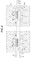
- Fig. 2 is a front sectional view for illustrating a state that an insulating rod is placed in a mold together with end fittings before an insulating material is molded around them; and
- Fig. 3 is a front sectional view of the composite insulator as prior art.
- The present invention will be explained in more detail based on an embodiment of the present invention with reference to the attached drawings.
- As shown in Figs. 1 and 2, a metallic end fitting 2 plated with zinc is connected to each of opposite end portions of a cylindrical insulating rod 1 made of FRP by crimping a
cylindrical barrel portion 3 of theend fitting 2. Theend fitting 2 includes thebarrel portion 3 in which a blind-hole is provided for receiving the end portion of the insulating rod 1, ajoint portion 5 at an axially outer side, and aflange portion 6 formed, at an outer end portion, integrally with thejoint portion 5 and thebarrel portion 3 and radially outwardly extending. In thejoint portion 5 is formed a hole through which a bolt not shown is passed. The end metallic fitting may be made of forged steel, ductile iron, malleable iron, aluminum, or the like. - Around the outer periphery of an exposed portion of the rod 1 and those of the barrel portion 1 of the
end fittings 2 is molded an elastic insulatingmaterial 8 made of silicon rubber, ethylene-propylene rubber or the like. The elasticinsulating material 8 includes a plurality ofshed portions 8a andsheath portions adjacent shed portions 8a or positioned axially outwardly from the axially outermost shed portions. In the illustrated embodiment, the thickness t1 of the elastic insulatingmaterial 8 molded around the outer periphery of the barrel portion of the end fitting is made greater than that t2 of the elastic insulatingmaterial 8 around the rod 1 by about 30 % to about 40 %. Further, the thickness t3 of theinsulating material 8 around the outer periphery of the rod 1 near thebarrel portion 3 is greater than that t2 of theinsulating material 8 around the outer periphery of a middle portion of the rod 1, and the length t4 of the thickened portion at t3 is greater than the thickness t3. - As is seen from the above, the
end fitting 2 is surrounded with a thicker portion of the elasticinsulating material 8 as compared with the rod 1. In this embodiment, the outer periphery of theflange 6 is continued to and flush with the outer peripheral surface of thesheath portion 8b' of the elastic insulatingmaterial 8 so that theflange 6 may not radially outwardly extend beyond thesheath portion 8b' of theelastic insulating member 8. The radiallyoutermost shed portion 8a is located near but axially inwardly from theflange 6. - Next, a process for producing the above composite insulator will be explained.
- First, an inner peripheral surface of the rod-inserting hole 7 in the metallic end fitting 2 plated with melted zinc is roughed by removing a plated layer at the inner peripheral surface of the hole 7 with using a boring tool or the like. Then, the rod 1 is inserted into the hole 7, and the
barrel portion 3 of theend fitting 2 is crimping to the outer periphery of the rod 1. When theend fitting 2 is to be crimping around the rod 1, crimping is effected first at a crimpingposition 3a at an axially inner tip side of the barrel portion in Fig. 2. Crimping is further effected in the order of crimpingpositions crimping positions 3a through 3d under different crimping forces or pressure by which thebarrel portion 3 is crimped. That is, the crimping pressure is 128 kgf/cm² at thecrimping position 3a, 150 kgf/cm² at thecrimping position 3b, 164 kgf/cm² at thecrimping position 3c, and 164 kgf/cm² at the crimpingposition 3d. That is, the crimping pressure is set greater as the crimping position approaches the axially outer side of the rod. In this embodiment, crimping is preferably effected in the state that the adjacent crimping locations partially overlap. In other words, it is preferable that the crimping force decreases as the crimping location approaches the open edge portion of the end fitting, so that high pressure is prevented from being applied to the insulating rod at the open edge portion of the end fitting. - After the end fittings are crimped around the rod 1, the elastic insulating
material 8 is molded. In order to mold the elastic insulatingmaterial 8, the rod 1 and thebarrel portions 3 of theend fittings 2 are placed inside a cavity Ka defined between mold units K1 and K2. When the temperature in the cavity reaches about 135°C, the elastic insulating material such as silicone rubber, ethylene propylene rubber or the like is charged in a melted state into the cavity around the rod and the barrel portions of the end fittings. The cavity Ka is heated at a given temperature (150°C∼180°C) for, e.g., 10 minutes to effect vulcanization. By so doing, the elastic insulatingmaterial 8 is cured and molded around the rod 1 and thebarrel portions 3 of theend fittings 2. At that time, the elastic insulatingmaterial 8 is molded around all the above-mentioned crimpingpositions 3a through 3d, while the elastic insulating material extends up to theflanges 6 of theend fittings 2 and is flush with the outer peripheral surface of theflange 6. - During the above producing process, although the melted elastic insulating
material 8 charged into the cavity Ka tends to flow toward the outer end of the end fitting 2 under influence of the molding pressure, this flow is interrupted by theflange 6 of theend fitting 2. Consequently, outside leakage of the elastic insulatingmaterial 8 is prevented to assuredly mold the elastic insulatingmaterial 8 around the predetermined locations of the end fittings. - Since the composite insulator is constituted above in this embodiment, the following effects can be obtained.
- (1) Since the elastic insulating
material 8 is molded around the rod 1 and thebarrel portions 3 of theend fittings 2, the entire axial length of the elastic insulatingmaterial 8 can be increased by lengths over which thebarrel portions 3 are molded with the insulatingmaterial 8. Accordingly, the insulating effective effective insulating length of the insulator can be increased without increasing the entire length of the insulator. Therefore, the effective insulating length of the composite insulator can be largely enhanced, and increase in the entire length of the composite insulator can be avoided. - (2) Since the vicinity of the rod-inserting hole 7 of the metallic end fitting 2 is covered with the elastic insulating
material 8, no separate sealing needs to be effected between the rod 1 and the rod-inserting hole 7. As a result, the producing process can be simplified, and the cost can be reduced. - (3) Since the large contact area between the
flange 6 and the elastic insulatingmaterial 8 can be ensured, water is difficult to invade between thebarrel portion 3 and the elastic insulatingmaterial 8. Therefore, no sealing is necessary between the barrel portion and the insulatingmaterial 8. As a result, the insulation can be ensured, the producing process can be simplified, and the cost can be reduced. - (4) Since the metallic end fitting 2 is provided with the
flange 6, the flowing of the elastic insulatingmaterial 8 can be assuredly interrupted by theflange 6 on molding the elastic insulatingmaterial 8 to prevent leakage of the insulating material outside the flange. - (5) The crimping pressure for the
barrel portion 3 becomes smaller as the crimping position approaches the open edge portion of the end fitting. In other words, the crimping pressure is made greater as the crimping position approaches the axially outer side. Accordingly, even if the rod 1 is thermally deformed (thermally expanded) on molding the elastic insulatingmaterial 8, an expanded portion of the rod can be escaped to the crimpingpositions material 8, the elastic insulating material can be prevented from entering between the insulating rod 1 and theend fittings 2, and reduction in the end forces of the end fitting 2 can be prevented. - (6) The thickness t1 of a portion of the elastic insulating
material 8 around the outer periphery of thebarrel portion 3 and the thickness t3 of a portion of the insulatingmaterial 8 around the outer periphery of the rod near the barrel portion are made greater than the thickness t2 of the elastic insulatingmaterial 8, and the length t4 of the thicken portion at t3 is made greater than the thickness t3. Therefore, thebarrel portion 3 of the end fitting 2 is surrounded with the thickened portion of the elastic insulatingmaterial 8 so that insulation between thebarrel portion 3 and the exterior and that between the end fittings can be assuredly ensured. Particularly, since the length t4 of the elastic insulatingmaterial 8 at the locations opposed to thebarrel portions 3 of both theend fittings 2 is set greater, theopposite barrel portions 3 can be assuredly insulated from each other. - (7) When the inner peripheral surface of the rod-inserting hole of the metallic end fitting is roughed by removing the plated layer on the inner peripheral surface, very small projections are formed on the wall surface of the rod-inserting hole 7. Thereby, when the rod 1 is inserted into the hole 7, and the
barrel portion 3 is crimped around the outer peripheral surface of the rod 1, the very small projections on the wall surface of the hole 7 bite the rod 1 so that the frictional resistance between the wall surface of the rod-inserting hole 7 and the rod 1 increases. As a result, the joining force between the rod 1 and the end fitting 2 is strengthened. - Since the crimping area of the end fitting is divided into plural zones along the axial direction of the rod 1 and the crimping is effected at such plural zones under application of different crimping pressures. Accordingly, reduction in the end force of the end fitting 2 due to the heat history of the rod on molding the elastic insulating
material 8 can be suppressed. - The present invention is not limited to the above-mentioned embodiment, but the invention may be employed in various manners given below by way of example without departing from the scope of the invention.
- (1) When the
barrel portion 3 of the end fitting 1 is to be crimped around the outer periphery of the insulating rod, the crimping positions (e.g., 3a to 3d) are not overlapped with one another. - (2) The
end fitting 2 is joined to the rod 1 in the state that thebarrel portion 3 is crimped around the outer periphery of the rod at each of the crimpingpositions 3a through 3d under application of the same crimping pressure. - (3) Two crimped positions are overlap with each other at their adjacent areas as at 3a and 3b, and the elastic insulating
material 8 is molded to cover the crimpingpositions - (4) The above explanation has been made by way of example mainly with respect to the case where the composite insulator according to the present invention will be employed in the electric power transmission system as one of the existing power transmission systems. The composite insulator according to the present invention may be used in other existing power transmission systems.
Claims (7)
- A composite insulator comprising an insulating rod, end fittings crimped to opposite end portions of said insulating rod, and an elastic insulating material molded around the outer periphery of the insulating rod, wherein each of said end fittings has a flange around the outer periphery of an end fitting portion on an axially external side thereof, and said elastic insulating material is molded around the outer periphery of the insulating rod and those of the end fitting portions such that the elastic material extends up to and between the flanges.
- The composite insulator according to Claim 1, wherein the outer peripheral surface of each of the flanges is substantially flush with that of the elastic insulating material.
- The composite insulator according to Claim 1 or 2, wherein a portion of the molded insulating material surrounding the end fittings is thicker than the remainder of the insulating material.
- The composite insulator according to Claim 1 or 2, wherein a area at which the end fitting is to be crimped around the outer periphery of the insulating rod is divided into a plurality of zones in an axial direction of the rod, and crimping pressures at said zones under which the end fitting is crimped around the outer periphery of the rod are made greater as the crimping zones approach an open edge portion of the end fitting.
- The composite insulator according to any one of Claims 1 through 4, wherein each of said end fittings has an axially cylindrical hole in each of said end fittings portions, said flange has a axially cylindrical outer shape, and said insulating rod is inserted into said axially cylindrical hole.
- The composite insulator according to any one of Claims 1 through 5, wherein the insulating material includes a plurality of shed portions and a sheath portion or sheath portions between the adjacent shed portions.
- A process for producing a composite insulator comprising an insulating rod, end fittings fitted around opposite end portions of said insulating rod, and an elastic insulating material around the outer periphery of the insulating rod, each of said end fittings having an axial hole therein and a flange around the outer periphery of an end fitting portion on an axially external side, said process comprising the steps of:(1) inserting the insulating rod into said holes of the end fittings at opposite ends thereof;(2) Crimping the end fittings around the outer periphery of the insulating rod;(3) placing the insulating rod having the end fittings inside a mold; and(4) molding around the outer periphery of the insulating rod and those of the end fitting portions such that the elastic material may extend up to and between the flanges.
Applications Claiming Priority (2)
| Application Number | Priority Date | Filing Date | Title |
|---|---|---|---|
| JP6057616A JP2723468B2 (en) | 1994-03-28 | 1994-03-28 | Polymer insulator |
| JP57616/94 | 1994-03-28 |
Publications (3)
| Publication Number | Publication Date |
|---|---|
| EP0675509A2 true EP0675509A2 (en) | 1995-10-04 |
| EP0675509A3 EP0675509A3 (en) | 1995-12-20 |
| EP0675509B1 EP0675509B1 (en) | 1998-07-22 |
Family
ID=13060817
Family Applications (1)
| Application Number | Title | Priority Date | Filing Date |
|---|---|---|---|
| EP95302045A Expired - Lifetime EP0675509B1 (en) | 1994-03-28 | 1995-03-27 | Composite insulators and a process for producing the same |
Country Status (5)
| Country | Link |
|---|---|
| US (1) | US6307157B1 (en) |
| EP (1) | EP0675509B1 (en) |
| JP (1) | JP2723468B2 (en) |
| CA (1) | CA2145619C (en) |
| DE (1) | DE69503545T2 (en) |
Cited By (2)
| Publication number | Priority date | Publication date | Assignee | Title |
|---|---|---|---|---|
| EP0859376A2 (en) * | 1997-02-13 | 1998-08-19 | Ngk Insulators, Ltd. | Polymer insulator |
| FR2761517A1 (en) * | 1997-03-25 | 1998-10-02 | Ngk Insulators Ltd | METHOD FOR FASTENING A POLYMER INSULATOR AND MATRIX USED THEREFOR |
Families Citing this family (14)
| Publication number | Priority date | Publication date | Assignee | Title |
|---|---|---|---|---|
| US6440344B2 (en) | 1997-03-11 | 2002-08-27 | Ngk Insulators, Ltd. | Method of manufacturing composite insulator and packing member for use in same |
| JP4601791B2 (en) * | 2000-09-14 | 2010-12-22 | 株式会社ダイヘン | Resin bushing |
| JP2002157932A (en) * | 2000-11-21 | 2002-05-31 | Furukawa Electric Co Ltd:The | Organic composite porcelain tube and its manufacturing method |
| CA2349253C (en) * | 2000-12-26 | 2009-11-17 | S&C Electric Company | Method and arrangement for providing a gas-tight housing joint |
| ATE521070T1 (en) * | 2007-05-23 | 2011-09-15 | Abb Technology Ag | HIGH VOLTAGE INSULATOR AND COOLING ELEMENT WITH THIS HIGH VOLTAGE INSULATOR |
| CN101159186B (en) * | 2007-11-12 | 2010-12-15 | 中国西电电气股份有限公司 | High-pressure hollow combined insulator high-pressure side once glue sealing method |
| JP2012248525A (en) * | 2011-05-31 | 2012-12-13 | Tokyo Electric Power Co Inc:The | Polymer insulator |
| WO2014130651A1 (en) * | 2013-02-20 | 2014-08-28 | Afl Telecommunications Llc | Manufacturing process and apparatus for crimping and/or swaging strain insulators |
| CN103971862B (en) * | 2014-05-21 | 2017-08-01 | 北京铁道工程机电技术研究所有限公司 | A kind of motor-car roof anti-soil dodges composite insulator |
| CN103971861A (en) * | 2014-05-21 | 2014-08-06 | 北京铁道工程机电技术研究所有限公司 | Motor train roof composite insulator with interface breakdown prevention function |
| CN109003757B (en) * | 2018-08-07 | 2023-09-12 | 重庆科技学院 | Crimping structure of composite insulator |
| CN110718343B (en) * | 2019-10-18 | 2020-11-06 | 江西正强电瓷电器有限公司 | Alumina porcelain core rod composite insulator and manufacturing method thereof |
| US11581111B2 (en) | 2020-08-20 | 2023-02-14 | Te Connectivity Solutions Gmbh | Composite polymer insulators and methods for forming same |
| CN114724789B (en) * | 2022-03-30 | 2023-08-01 | 南京电气(集团)高新材料有限公司 | Crimping device for assembling insulator and flange |
Citations (3)
| Publication number | Priority date | Publication date | Assignee | Title |
|---|---|---|---|---|
| CH491474A (en) * | 1968-07-13 | 1970-05-31 | Siemens Ag | Electrical insulating body and process for its manufacture |
| DE1932949A1 (en) * | 1969-06-28 | 1971-01-07 | Bbc Brown Boveri & Cie | High-voltage composite insulator |
| EP0439411A1 (en) * | 1990-01-26 | 1991-07-31 | Société Nouvelle des Etablissements Dervaux, S.A. | Composite insulator and its manufacturing process |
Family Cites Families (5)
| Publication number | Priority date | Publication date | Assignee | Title |
|---|---|---|---|---|
| US3898372A (en) * | 1974-02-11 | 1975-08-05 | Ohio Brass Co | Insulator with resin-bonded fiber rod and elastomeric weathersheds, and method of making same |
| US4045604A (en) * | 1974-10-08 | 1977-08-30 | Raychem Limited | Recoverable article with outwardly extending hollow heat flanges; kit including such article and a cylindrical substrate; and method of making such article |
| CH589347A5 (en) * | 1974-12-05 | 1977-06-30 | Cossonay Cableries Trefileries | |
| FR2511180A1 (en) * | 1981-08-05 | 1983-02-11 | Ceraver | ELECTRICALLY INSULATING ELEMENT COMPRISING A MONOBLOC FAN GROUP |
| US5043838A (en) * | 1989-03-31 | 1991-08-27 | Hubbell Incorporated | Modular electrical assemblies with pressure relief |
-
1994
- 1994-03-28 JP JP6057616A patent/JP2723468B2/en not_active Expired - Lifetime
-
1995
- 1995-03-20 US US08/406,392 patent/US6307157B1/en not_active Expired - Lifetime
- 1995-03-27 EP EP95302045A patent/EP0675509B1/en not_active Expired - Lifetime
- 1995-03-27 CA CA002145619A patent/CA2145619C/en not_active Expired - Lifetime
- 1995-03-27 DE DE69503545T patent/DE69503545T2/en not_active Expired - Lifetime
Patent Citations (3)
| Publication number | Priority date | Publication date | Assignee | Title |
|---|---|---|---|---|
| CH491474A (en) * | 1968-07-13 | 1970-05-31 | Siemens Ag | Electrical insulating body and process for its manufacture |
| DE1932949A1 (en) * | 1969-06-28 | 1971-01-07 | Bbc Brown Boveri & Cie | High-voltage composite insulator |
| EP0439411A1 (en) * | 1990-01-26 | 1991-07-31 | Société Nouvelle des Etablissements Dervaux, S.A. | Composite insulator and its manufacturing process |
Cited By (3)
| Publication number | Priority date | Publication date | Assignee | Title |
|---|---|---|---|---|
| EP0859376A2 (en) * | 1997-02-13 | 1998-08-19 | Ngk Insulators, Ltd. | Polymer insulator |
| EP0859376A3 (en) * | 1997-02-13 | 1999-02-03 | Ngk Insulators, Ltd. | Polymer insulator |
| FR2761517A1 (en) * | 1997-03-25 | 1998-10-02 | Ngk Insulators Ltd | METHOD FOR FASTENING A POLYMER INSULATOR AND MATRIX USED THEREFOR |
Also Published As
| Publication number | Publication date |
|---|---|
| JP2723468B2 (en) | 1998-03-09 |
| JPH07272558A (en) | 1995-10-20 |
| DE69503545T2 (en) | 1999-01-21 |
| EP0675509B1 (en) | 1998-07-22 |
| DE69503545D1 (en) | 1998-08-27 |
| CA2145619A1 (en) | 1995-09-29 |
| US6307157B1 (en) | 2001-10-23 |
| EP0675509A3 (en) | 1995-12-20 |
| CA2145619C (en) | 1998-08-25 |
Similar Documents
| Publication | Publication Date | Title |
|---|---|---|
| EP0675509B1 (en) | Composite insulators and a process for producing the same | |
| EP0617433B1 (en) | Composite electrical insulator | |
| US6065207A (en) | Composite insulators and a process for producing the same | |
| US5901987A (en) | Method of making an endpiece, an endpiece and a connector made by the method, and a circuit including such a connector | |
| DE102017121459A1 (en) | Cable seal and arrangement with a housing | |
| JPH0475604B2 (en) | ||
| EP3304665B1 (en) | A rigid joint assembly | |
| EP0084264A2 (en) | Molded high voltage splice body | |
| WO2009051721A1 (en) | Integrated insulator seal and shield assemblies | |
| JPS6255367B2 (en) | ||
| EP1043734B1 (en) | Composite electrical insulator, method of assembling the same and method of manufacturing the same | |
| US5017161A (en) | Electric terminal connector | |
| US5914462A (en) | Composite insulator having end fittings with gaps | |
| GB2104171A (en) | Method of joining an insulating rod to a metal end piece | |
| CN210350763U (en) | Cable joint butt joint cold shrink pipe | |
| US4126498A (en) | Boots for wire rope terminations | |
| KR200409094Y1 (en) | Polymer suspension insulator for electric distribution | |
| US4623213A (en) | Method for joining two aluminum conductors of electric cables and the joint thus obtained | |
| US11581111B2 (en) | Composite polymer insulators and methods for forming same | |
| JP2723468C (en) | ||
| JP2001084854A (en) | Polymer insulator and its manufacture | |
| JPH06233439A (en) | Rubber-molded cable head | |
| JP2000295752A (en) | Method of forming insulating tube and cable connection | |
| CS269490B1 (en) | Insulation joint |
Legal Events
| Date | Code | Title | Description |
|---|---|---|---|
| PUAI | Public reference made under article 153(3) epc to a published international application that has entered the european phase |
Free format text: ORIGINAL CODE: 0009012 |
|
| AK | Designated contracting states |
Kind code of ref document: A2 Designated state(s): DE FR GB |
|
| PUAL | Search report despatched |
Free format text: ORIGINAL CODE: 0009013 |
|
| AK | Designated contracting states |
Kind code of ref document: A3 Designated state(s): DE FR GB |
|
| 17P | Request for examination filed |
Effective date: 19960108 |
|
| 17Q | First examination report despatched |
Effective date: 19960219 |
|
| GRAG | Despatch of communication of intention to grant |
Free format text: ORIGINAL CODE: EPIDOS AGRA |
|
| GRAG | Despatch of communication of intention to grant |
Free format text: ORIGINAL CODE: EPIDOS AGRA |
|
| GRAH | Despatch of communication of intention to grant a patent |
Free format text: ORIGINAL CODE: EPIDOS IGRA |
|
| GRAH | Despatch of communication of intention to grant a patent |
Free format text: ORIGINAL CODE: EPIDOS IGRA |
|
| GRAA | (expected) grant |
Free format text: ORIGINAL CODE: 0009210 |
|
| AK | Designated contracting states |
Kind code of ref document: B1 Designated state(s): DE FR GB |
|
| REF | Corresponds to: |
Ref document number: 69503545 Country of ref document: DE Date of ref document: 19980827 |
|
| ET | Fr: translation filed | ||
| PLBE | No opposition filed within time limit |
Free format text: ORIGINAL CODE: 0009261 |
|
| STAA | Information on the status of an ep patent application or granted ep patent |
Free format text: STATUS: NO OPPOSITION FILED WITHIN TIME LIMIT |
|
| 26N | No opposition filed | ||
| REG | Reference to a national code |
Ref country code: GB Ref legal event code: IF02 |
|
| PGFP | Annual fee paid to national office [announced via postgrant information from national office to epo] |
Ref country code: GB Payment date: 20050317 Year of fee payment: 11 |
|
| PG25 | Lapsed in a contracting state [announced via postgrant information from national office to epo] |
Ref country code: GB Free format text: LAPSE BECAUSE OF NON-PAYMENT OF DUE FEES Effective date: 20060327 |
|
| GBPC | Gb: european patent ceased through non-payment of renewal fee |
Effective date: 20060327 |
|
| PGFP | Annual fee paid to national office [announced via postgrant information from national office to epo] |
Ref country code: FR Payment date: 20140311 Year of fee payment: 20 |
|
| PGFP | Annual fee paid to national office [announced via postgrant information from national office to epo] |
Ref country code: DE Payment date: 20140417 Year of fee payment: 20 |
|
| REG | Reference to a national code |
Ref country code: DE Ref legal event code: R071 Ref document number: 69503545 Country of ref document: DE |