EP0675261B1 - Roller door with flexible door leaf - Google Patents
Roller door with flexible door leaf Download PDFInfo
- Publication number
- EP0675261B1 EP0675261B1 EP19950102452 EP95102452A EP0675261B1 EP 0675261 B1 EP0675261 B1 EP 0675261B1 EP 19950102452 EP19950102452 EP 19950102452 EP 95102452 A EP95102452 A EP 95102452A EP 0675261 B1 EP0675261 B1 EP 0675261B1
- Authority
- EP
- European Patent Office
- Prior art keywords
- roller
- door
- door leaf
- door according
- slide
- Prior art date
- Legal status (The legal status is an assumption and is not a legal conclusion. Google has not performed a legal analysis and makes no representation as to the accuracy of the status listed.)
- Expired - Lifetime
Links
Images


Classifications
-
- E—FIXED CONSTRUCTIONS
- E06—DOORS, WINDOWS, SHUTTERS, OR ROLLER BLINDS IN GENERAL; LADDERS
- E06B—FIXED OR MOVABLE CLOSURES FOR OPENINGS IN BUILDINGS, VEHICLES, FENCES OR LIKE ENCLOSURES IN GENERAL, e.g. DOORS, WINDOWS, BLINDS, GATES
- E06B9/00—Screening or protective devices for wall or similar openings, with or without operating or securing mechanisms; Closures of similar construction
- E06B9/56—Operating, guiding or securing devices or arrangements for roll-type closures; Spring drums; Tape drums; Counterweighting arrangements therefor
- E06B9/58—Guiding devices
- E06B9/581—Means to prevent or induce disengagement of shutter from side rails
-
- E—FIXED CONSTRUCTIONS
- E06—DOORS, WINDOWS, SHUTTERS, OR ROLLER BLINDS IN GENERAL; LADDERS
- E06B—FIXED OR MOVABLE CLOSURES FOR OPENINGS IN BUILDINGS, VEHICLES, FENCES OR LIKE ENCLOSURES IN GENERAL, e.g. DOORS, WINDOWS, BLINDS, GATES
- E06B9/00—Screening or protective devices for wall or similar openings, with or without operating or securing mechanisms; Closures of similar construction
- E06B9/02—Shutters, movable grilles, or other safety closing devices, e.g. against burglary
- E06B9/08—Roll-type closures
- E06B9/11—Roller shutters
- E06B9/13—Roller shutters with closing members of one piece, e.g. of corrugated sheet metal
- E06B2009/135—Horizontal shutter reinforcements
-
- E—FIXED CONSTRUCTIONS
- E06—DOORS, WINDOWS, SHUTTERS, OR ROLLER BLINDS IN GENERAL; LADDERS
- E06B—FIXED OR MOVABLE CLOSURES FOR OPENINGS IN BUILDINGS, VEHICLES, FENCES OR LIKE ENCLOSURES IN GENERAL, e.g. DOORS, WINDOWS, BLINDS, GATES
- E06B9/00—Screening or protective devices for wall or similar openings, with or without operating or securing mechanisms; Closures of similar construction
- E06B9/56—Operating, guiding or securing devices or arrangements for roll-type closures; Spring drums; Tape drums; Counterweighting arrangements therefor
- E06B9/58—Guiding devices
- E06B2009/585—Emergency release to prevent damage of shutter or guiding device
Definitions
- the invention relates to a roller door with a flexible door leaf that is on a top the gate opening rotatably mounted, drivable winding shaft can be wound on the a balancing torque to balance the weight of the hanging door leaf acts, with a quiet attached to the lower end of the door leaf, the two ends are provided with holding pieces on which are mounted on rollers mounted in the floor area running and the door leaf exciting ropes are attached, and with the door opening laterally delimiting, consisting of profiles, the vertical slots into which the side edges of the door leaf protrude.
- a roller door known from DE-A-34 11 664, for example, the one specified at the beginning Kind is that which runs off the winding shaft and is wound onto it Door leaf through at the ends of the bar closing the door leaf downwards, ropes that protrude laterally into the boundary profiles of the roller shutter curtains taut, the one attached to the winding shaft or rotatably mounted on it Winding drums are wound up and unwound, the tension of the Tensioning ropes with torsion springs or pulley-like reeving of the tensioning rope is generated with a bottom block acted upon by spring force and additionally Resilient compensation devices are provided to compensate for the path differences to compensate for the different winding diameters of the wound Roller door and the tensioning cables or - wound on the winding drum straps results.
- a roller door known from DE-C-40 07 280 avoids predetermined breaking points and damage to the door leaf in the event of a start in that the slots in the side profiles gripping ends or guide pieces of the closing the door leaf Last made of a highly elastic material, so that the end areas of the end strip from the damage-free Slits in the side profiles can emerge when the Bar, for example in the event of a start-up, with a corresponding high lateral force is applied.
- the lower one End strip from the side guide slots of the side profiles pushed out, the side edges also kick of the door leaf out of the slots and lose their leadership, so that at least the lower end of the door leaf in uncontrollable Can swing out and flutter.
- the object of the invention is therefore a roller door of the type specified To create the way in which the door leaf closes In the event of impermissibly high transverse forces can swing out without damage and where the gate after one Swing out the end strip quickly and easily again in its normal operating position can be brought without tightening the door leaf can be dispensed with by tension cables acting on the end strip got to.
- this object is achieved with a roller door of the generic type Art solved in that the necessary for leaf tension Tension cables no longer in the rope gate supports Appropriate shots of the end strip are attached instead on holding pieces of the end profile, which are not on the side protrude more into the side profiles.
- each of the profiles in a slide slidably guided vertically for each of the profiles is on its holding part that protrudes the profiles towards the center of the door between top and bottom with one end each Ledge connected holding pieces is bordered such that the Holding part can only emerge laterally between these, and that each tensioning cable is connected to an upper end region of the bar and through a channel or gap in the sled the bottom pulley runs.
- the sled provided in this embodiment is improved the management and stabilization of the final profile and ensures that the pull cables in the side slots of the profiles be performed more wear-free.
- the roller door is the one that closes the door leaf Strip with their two side end areas on the two in the lateral profiles that delimit the door opening Carriage held, the connection inadmissible when it occurs high lateral forces, for example in the event of a start by a vehicle, is lifted without the Release the tension cables from the end bar.
- the roller shutter occur between the ends of the end bar and the slide essentially only vertical forces on by the top and bottom brackets of the bottom bar be transferred to the holding parts of the sled.
- the holding part of the slide is between the fork-shaped holding pieces of the end strip by the Tension rope fixed, which absorbs lateral forces by the fact that it on the side walls of the channel or gap of the sled creates.
- the end bar can be between step out the side profiles that delimit the door opening or swing out, still using the two tension cables remains connected so that an uncontrolled swinging out of the lower area of the door leaf and unwanted flutter is prevented in the event of a crash.
- the door leaf exciting and with the bottom end strip connected ropes are in the channels or columns of the Carriage guided in such a way that even in the case of a lateral Do not push the end strip away from the sled come into contact with the edges of the guide slots and thereby can be damaged.
- each carriage has an upper and one lower stop surface, which are bordered by the holding pieces.
- the carriage can be made from one on opposite sides blocks provided with mutually parallel grooves, the Grooves overlap the profile webs delimiting the slot.
- a such a configuration leads to a particularly simple structure of the carriage, the block preferably made of a plastic with good sliding properties.
- the block can have a gap in the plane of the door leaf be by two disc-shaped connectors or two roles supporting axles is bridged. According to this configuration the block is formed in two parts, the between these parts formed by the two guide slot Parts connecting connectors are bridged, either formed by round sliding surfaces for the tension cables or rollers are.
- the connecting pieces or the axles carrying the rollers are expediently at approximately diagonally opposite one another Corner areas of approximately square or rectangular, the gap delimiting walls of the essentially cuboid block arranged so that good guidance of the tensioning cables is ensured is.
- the holding pieces of the end strip are expediently of mutually parallel, forked connected to the bar, flat profile pieces. In this way, the end bar in the event of inadmissibly high transverse forces from the Slide or slide blocks are pushed off.
- the lower, flat profile piece is made of elastic material.
- This configuration allows for a lateral Pushing the end strip away from the guide block or slide automatically engaging in the operating state again to cause the gate to be fully closed Position is driven, then the sled or block with such a force against the lower profile piece made of elastic Material creates that this is bent upwards and the holding part of the carriage or block in its holding position snaps.
- each Tensioning rope counter to the door leaf on one with the winding shaft connected drum can be wound up and unwound and that between the bottom pulley and the drum the tension cable between two frame-fixed pulleys and the role of one between them arranged bottom block, which is opposite the floor area is tensioned by a tension spring, pulley-like reeving is.
- the roller door according to the invention can be, for example due to a crash of the end profile from the guide sled quickly and easily and even automatically return to its operating state.
- the roller door according to the invention with a device for leaf tension and weight compensation Mistake.
- the Roller door according to the invention for its installation no additional width the gate opening required so that the existing clear width of the gate can be fully used.
- An unwanted and uncontrolled Swinging out and fluttering of the lower part of the Door leaf is avoided after a crash.
- the roller door according to the invention is also characterized in that the lower end strip in the event of a crash regardless of this can safely release, no matter where it hits has been.
- the roller door according to the invention consists of a in the usual way winding shaft with its diameter mounted above the gate opening magnifying winding cylinder 1 on which the flexible door leaf 2 can be wound up.
- On the winding shaft is in the area of the gate opening laterally delimiting profiles, of which in the Figures 2 and 4 to 5 the right profile 5 is shown, a Fixed winding drum 3, on the opposite to the door leaf 2 A tension cable 4 can be wound.
- Each of the two tension cables 4 runs from the winding drum 3 over two deflection rollers mounted on the frame or in the side profiles 5 6, 7 and a roller 8 arranged between them Bottom block via a deflection roller mounted on the base plate 9 10 to its fixed point 11 on the upper holding piece 12, the on the end bar arranged at the lower edge of the door leaf 2 13 is attached.
- the Deflection roller 8 carrying bottom block is the top of one Tension spring 14 attached, the lower end attached to a tab 15 is connected to the axis 16 of the deflection roller 10 is.
- the winding shaft or the winding cylinder 1 for the door leaf 2 is by a counterweight whose strap or tether on one the winding shaft attached drum is wound or by a tension spring in the winding direction with a compensating torque charged, but taking into account that of the Tension rope on the winding shaft is exerted so large that the door leaf is wholly or partially wound on the winding cylinder if, in the event of a power failure, the brake of the Drive motor is vented.
- Each of the side profiles 5 of the goal frame has in its a surface pointing towards the center of the door Slot 18, which is limited by the webs 19, 20 of the profile 5 becomes.
- this slot is a roughly cuboid Block 21 made of plastic with a low coefficient of friction performed, provided on opposite sides with grooves 22, 23 in which the webs 19, 20 of the side profile 5 engage.
- the block 21 is in its vertical center plane with a Gap 24 provided by two disc-like connectors 25, 26 is bridged, the two also approximately cuboid Connect the holding parts 27, 28 of the block 21 together.
- the disc-like connectors 25, 26 are in the 2 apparent manner approximately diagonally to the rectangular or square walls of the block delimiting the gap 24 21 arranged.
- the holding pieces 12, 32 which consist of flat profile pieces and the ends of the bar or the end profile 13 in the manner shown in FIG. 2 protrude fork-like, fastened by screws.
- the out Fig. 5 apparent operating position summarize the final profile 13 protruding holding pieces 12, 32 the guide slot 18 protruding part of the block 21 fork-shaped between them a.
- the holding pieces 12, 32 avoided by the block 21 in that the tensioning cable 4 is held and centered on the gap 24 delimiting, inner side walls of the block 21 creates.
- the end profile 13 thereby clicks off the guide block 21 from that the holding pieces 12, 32 of this in the 6 apparent manner with the entrainment of the tensioning cable 4th be pushed away.
- the rope 4 slips over the upper, rounded one Edge of the gap 24 in the one shown in FIGS. 2 and 6 Way, without limiting the guide gap 18 Profile bars to connect.
- the lower holding piece 32 can consist of elastic material, so that after disengaging the end profile 13 an automatic It can be latched in that the gate is in the direction is moved to its closed position.
- the upper one lays down Edge of the block 21 against the lower outside of the flexible Stop piece 32 in such a way that it is bent upwards until the holding block 21 snaps into its operating position slips over this.
- the lower holding piece can be used accordingly be shorter, with a corresponding Game of the holding block between the holding pieces 12, 32 is provided becomes.
Description
Die Erfindung betriffl ein Rolltor mit einem flexiblen Torblatt, das auf eine oberhalb der Toröffnung drehbar gelagerte, antreibbare Wickelwelle aufwickelbar ist, auf die zum Ausgleich des Gewichts des herabhängenden Torblatts ein Ausgleichsmoment wirkt, mit einer am unteren Ende des Torblatts befestigten Leise, deren beiden Enden mit Haltestücken versehen sind, an denen über im Bodenbereich gelagerte Rollen laufende und das Torblatt spannende Seile befestigt sind, und mit die Toröffnung seitlich begrenzenden, aus Profilen bestehenden Seitenteilen, die vertikale Schlitze aufweisen, in die die seitlichen Ränder des Torblatts ragen.The invention relates to a roller door with a flexible door leaf that is on a top the gate opening rotatably mounted, drivable winding shaft can be wound on the a balancing torque to balance the weight of the hanging door leaf acts, with a quiet attached to the lower end of the door leaf, the two ends are provided with holding pieces on which are mounted on rollers mounted in the floor area running and the door leaf exciting ropes are attached, and with the door opening laterally delimiting, consisting of profiles, the vertical slots into which the side edges of the door leaf protrude.
Bei einem beispielsweise aus DE-A-34 11 664 bekannten Rolltor der eingangs angegebenen Art wird das von der Wickelwelle ablaufende und auf diese aufgewickelte Torblatt durch an den Enden der das Torblatt nach unten hin abschließenden Leiste, die seitlich in die Begrenzungsprofile der Rolltorbehänge hineinragt, befestigte Seile straff gespannt, die auf an der Wickelwelle befestigte oder auf dieser drehbar gelagerten Wickeltrommeln auf- und abgewickelt werden, wobei die Spannung der Spannseile durch Torsionsfedern oder Flaschenzugartige Einscherung des Spannseils mit einer durch Federkraft beaufschlagten Unterflasche erzeugt wird und zusätzlich federnde Ausgleichsvorrichtungen vorgesehen sind, um die Wegdifferenzen auszugleichen, die sich aus den unterschiedlichen Wickeldurchmessern des aufgewickelten Rolltors und der auf die Wickeltrommel aufgewickelten Spannseile oder - gurte ergibt. In a roller door known from DE-A-34 11 664, for example, the one specified at the beginning Kind is that which runs off the winding shaft and is wound onto it Door leaf through at the ends of the bar closing the door leaf downwards, ropes that protrude laterally into the boundary profiles of the roller shutter curtains taut, the one attached to the winding shaft or rotatably mounted on it Winding drums are wound up and unwound, the tension of the Tensioning ropes with torsion springs or pulley-like reeving of the tensioning rope is generated with a bottom block acted upon by spring force and additionally Resilient compensation devices are provided to compensate for the path differences to compensate for the different winding diameters of the wound Roller door and the tensioning cables or - wound on the winding drum straps results.
Bei üblicherweise schnell laufenden Rolltoren der eingangs angegebenen Art kann es vorkommen, daß das Tor von dieses passierenden Fahrzeugen insbesondere im Bereich der unteren Abschlußleiste angefahren wird, so daß dieses beschädigt wird und ausfällt und aufwendige Reparaturen erforderlich sind. Um derartige Schäden bei einem Anfahren des Rolltors gering zu halten, ist es bekannt, die untere Abschlußleiste des Torblatts, deren Enden in den Schlitzen der die Toröffnung seitlich begrenzenden Profile geführt sind, mit Sollbruchstellen zu versehen. Tritt eine Beschädigung des Tors infolge eines Anfahrens auf, läßt sich dieses sodann verhältnismäßig einfach und schnell reparieren.In the case of usually high-speed roller doors of the type specified at the beginning Art can happen that the gate of this passing Vehicles especially in the area of the lower end strip is approached so that it is damaged and fails and expensive repairs are required. To such damage to keep it low when starting up the roller door, it is known the bottom end strip of the door leaf, the ends of which in the slots of the profiles laterally delimiting the gate opening are to be provided with predetermined breaking points. Occurs damage of the gate as a result of a start, this can be done then relatively easy and quick repair.
Ein aus DE-C- 40 07 280 bekanntes Rolltor vermeidet Sollbruchstellen und Beschädigungen des Torblatts im Falle eines Anfahrens dadurch, daß die in die Schlitze der seitlichen Profile greifenden Enden oder Führungsstücke der das Torblatt abschließenden Leiste aus einem hochelastischen Werkstoff bestehen, so daß die Endbereiche der Abschlußleiste beschädigungsfrei aus den Schlitzen der seitlichen Profile heraustreten können, wenn die Leiste, beispielsweise im Falle eines Anfahrens, mit einer entsprechend hohen Querkraft beaufschlagt wird. Wird jedoch die untere Abschlußleiste aus den seitlichen Führungsschlitzen der seitlichen Profile herausgedrückt, treten auch die Seitenkanten des Torblattes aus den Schlitzen heraus und verlieren ihre Führung, so daß zumindest das untere Ende des Torblatts in unkontrollierbarer Weise ausschwenken und flattern kann. Um das Tor nach einem Crash wieder in seinen gebrauchsfähigen Zustand zu bringen, ist es daher erforderlich, die Enden des Abschlußprofils und die Seitenkanten des Torblatts wieder in die Führungsschlitze der seitlichen Profile einzuführen, was verhältnismäßig aufwendig sein kann. Zur Erleichterung dieses Einführens der Abschlußleiste und der seitlichen Ränder des Torblattes in die Führungsschlitze nach einem Crash ist es aus DE-C- 40 07 280 und DE-U- 93 14 952 bekannt, die oberen Enden der schlitzartigen Führungen mit trichterförmigen Erweiterungen zu versehen.A roller door known from DE-C-40 07 280 avoids predetermined breaking points and damage to the door leaf in the event of a start in that the slots in the side profiles gripping ends or guide pieces of the closing the door leaf Last made of a highly elastic material, so that the end areas of the end strip from the damage-free Slits in the side profiles can emerge when the Bar, for example in the event of a start-up, with a corresponding high lateral force is applied. However, the lower one End strip from the side guide slots of the side profiles pushed out, the side edges also kick of the door leaf out of the slots and lose their leadership, so that at least the lower end of the door leaf in uncontrollable Can swing out and flutter. To the gate after a crash back to its usable condition bring, it is therefore necessary to end the end profile and the side edges of the door leaf back into the guide slots to introduce lateral profiles, which is proportionate can be expensive. To facilitate this insertion of the end strip and the side edges of the door leaf in the Guide slots after a crash, it is from DE-C- 40 07 280 and DE-U-93 14 952 known, the upper ends of the slot-like guides to be provided with funnel-shaped extensions.
Abgesehen von der Schwierigkeit, bei den bekannten Rolltoren in sogenannter "Crash-Ausführung" die Abschlußleiste und die Seitenränder des Torblatts wieder in die Führungsschlitze einzuführen, weisen diese den Nachteil auf, daß die Abschlußleiste zur Straffung des Torblattes im Falle des Auftretens unzulässig hoher Querkräfte auf das Abschlußprofil nicht auslenken kann, weil die Blattspannung auf in die Seitenstütze hineinragende Verlängerungen des Abschlußprofils wirkt. Um bei bekannten Rolltoren in sogenannter "Crash-Ausführung" dennoch das Troblatt straff halten zu können, muß die Abschlußleiste entsprechend schwer ausgebildet werden, damit diese ein zur Straffung des Torblattes ausreichendes Gewicht aufweist.Apart from the difficulty with the well-known roller shutters in the so-called "crash version" the end strip and the side edges reinsert the door leaf into the guide slots, these have the disadvantage that the end strip for tightening of the door leaf in the event of an impermissibly high level Can not deflect lateral forces on the end profile, because the Leaf tension on extensions protruding into the side support of the final profile acts. In order with known roller doors in so-called "Crash version" nevertheless keep the trough taut to be able to, the end strip must be made correspondingly heavy so that it is sufficient to tighten the door leaf Has weight.
Aufgabe der Erfindung ist es daher, ein Rolltor der eingangs angegebenen Art zu schaffen, bei dem die das Torblatt abschließende Leiste im Falle des Auftretens unzulässig hoher Querkräfte beschädigungsfrei ausschwingen kann und bei dem das Tor nach einem Ausschwingen der Abschlußleiste schnell und einfach wieder in seinen eine normale Funktion gewährleistende Betriebsstellung gebracht werden kann, ohne daß auf eine Straffung des Torblattes durch auf die Abschlußleiste wirkende Spannseile verzichtet werden muß.The object of the invention is therefore a roller door of the type specified To create the way in which the door leaf closes In the event of impermissibly high transverse forces can swing out without damage and where the gate after one Swing out the end strip quickly and easily again in its normal operating position can be brought without tightening the door leaf can be dispensed with by tension cables acting on the end strip got to.
Erfindungsgemäß wird diese Aufgabe bei einem Rolltor der gattungsgemäßen Art dadurch gelöst, daß die zur Blattspannung notwendigen Spannseile nicht mehr in den seilichen Torstützen an entsprechenden Aufnahmen der Abschlußleiste befestigt werden sondern an Haltestücken des Abschlußprofils, welche seitlich nicht mehr in die Seitenprofile hineinragen.According to the invention, this object is achieved with a roller door of the generic type Art solved in that the necessary for leaf tension Tension cables no longer in the rope gate supports Appropriate shots of the end strip are attached instead on holding pieces of the end profile, which are not on the side protrude more into the side profiles.
Nach einer vorteilhaften Ausgestaltung ist vorgesehen, daß in jedem der Profile ein Schlitten vertikal verschieblich geführt ist, der an seinem die Profile zur Tormitte hin überragenden Halteteil zwischen oberen und unteren mit jeweils einem Ende der Leiste verbundenen Haltestücken derart eingefaßt ist, daß das Halteteil nur seitlich zwischen diesen heraustreten kann, und daß jedes Spannseil mit einem oberen Endbereich der Leiste verbunden ist und durch einen Kanal oder Spalt des Schlittens zu der bodenseitigen Umlenkrolle verläuft.According to an advantageous embodiment it is provided that in a slide slidably guided vertically for each of the profiles is on its holding part that protrudes the profiles towards the center of the door between top and bottom with one end each Ledge connected holding pieces is bordered such that the Holding part can only emerge laterally between these, and that each tensioning cable is connected to an upper end region of the bar and through a channel or gap in the sled the bottom pulley runs.
Der nach dieser Ausführungsform vorgesehene Schlitten verbessert die Führung und stabilisierung des Abschlußprofils und gewährleistet, daß die Zugseile in den seitlichen Schlitzen der Profile verschleißfreier geführt werden. Bei dieser bevorzugten Ausführungsform des Rolltors ist die das Torblatt abschließende Leiste mit ihren beiden seitlichen Endbereichen an den beiden in den seitlichen, die Toröffnung begrenzenden Profilen geführten Schlitten gehalten, wobei die Verbindung beim Auftreten unzulässig hoher Querkräfte, beispielsweise im Falle des Anfahrens durch ein Fahrzeug, aufgehoben wird, ohne daß sich jedoch die Spannseile von der Abschlußleiste lösen. Während des normalen Betriebes des Rolltores treten zwischen den Enden der Abschlußleiste und des Schlittens im wesentlichen nur vertikale Kräfte auf, die von den oberen und unteren Haltestücken der Abschlußleiste auf die Halteteile der Schlitten übertragen werden. In seitlicher Richtung ist das Halteteil des Schlittens zwischen den gabelförmigen Haltestücken der Abschlußleiste durch das Spannseil fixiert, das seitliche Kräfte dadurch aufnimmt, daß es sich an die Seitenwandungen des Kanals oder Spalts des Schlittens anlegt. Sind jedoch die auf das Torblatt bzw. die untere Abschlußleiste wirkenden Querkräfte so groß, daß die Haltestücke der Abschlußleiste in seitlicher Richtung von dem Halteteil des Schlittens abgeschoben werden, kann die Abschlußleiste zwischen den seitlichen, die Toröffnung begrenzenden Profilen heraustreten oder ausschwingen, wobei sie noch immer mit den beiden Spannseilen verbunden bleibt, so daß ein unkontrolliertes Ausschwingen des unteren Bereiches des Torblattes und unerwünschtes Flattern im Falle eines Crash verhindert wird. Um nach einem Crash das Tor wieder in seinen betriebsbereiten Zustand zu verbringen, ist es nur erforderlich, die Haltestücke seitlich wieder über das Halteteil des Schlittens zu schieben und die Randbereiche des Torblattes wieder in die Führungsschlitze zu drücken.The sled provided in this embodiment is improved the management and stabilization of the final profile and ensures that the pull cables in the side slots of the profiles be performed more wear-free. In this preferred embodiment of the roller door is the one that closes the door leaf Strip with their two side end areas on the two in the lateral profiles that delimit the door opening Carriage held, the connection inadmissible when it occurs high lateral forces, for example in the event of a start by a vehicle, is lifted without the Release the tension cables from the end bar. During normal Operation of the roller shutter occur between the ends of the end bar and the slide essentially only vertical forces on by the top and bottom brackets of the bottom bar be transferred to the holding parts of the sled. In laterally the holding part of the slide is between the fork-shaped holding pieces of the end strip by the Tension rope fixed, which absorbs lateral forces by the fact that it on the side walls of the channel or gap of the sled creates. However, are those on the door leaf or the lower one End strip acting transverse forces so large that the holding pieces the end strip in the lateral direction from the holding part of the Slid off, the end bar can be between step out the side profiles that delimit the door opening or swing out, still using the two tension cables remains connected so that an uncontrolled swinging out of the lower area of the door leaf and unwanted flutter is prevented in the event of a crash. To after a crash to return the gate to its operational state, it is only necessary to slide the holding pieces over again laterally to slide the holding part of the slide and the edge areas of the door leaf into the guide slots again.
Da grundsätzlich nur die untere Abschlußleiste und der mit dieser verbundene untere Teil des Torblattes im Falle unzulässig hoher Querkräfte beschädigungsfrei aus den Führungen der seitlichen Profile austreten müssen, können die seitlichen Ränder des darüberliegenden Teils des Torblattes in üblicher Weise in den Führungsschlitzen durch Halteelemente geführt sein, wie sie beispielsweise aus EP-A-0 157 198 bekannt sind. Since basically only the bottom end bar and the one with this connected lower part of the door leaf is inadmissible in the case high lateral forces without damage from the guides of the side Profiles must emerge, the lateral edges of the overlying part of the door leaf in the usual way in the Guide slots can be guided by holding elements, such as, for example are known from EP-A-0 157 198.
Die das Torblatt spannenden und mit der unteren Abschlußleiste verbundenen Spannseile sind in den Kanälen oder Spalten des Schlittens derart geführt, daß sie auch im Falle eines seitlichen Wegdrückens der Abschlußleiste von den Schlitten nicht mit den Kanten der Führungsschlitze in Berührung kommen und dadurch beschädigt werden können.The door leaf exciting and with the bottom end strip connected ropes are in the channels or columns of the Carriage guided in such a way that even in the case of a lateral Do not push the end strip away from the sled come into contact with the edges of the guide slots and thereby can be damaged.
Zweckmäßigerweise besitzt jeder Schlitten eine obere und eine untere Anschlagfläche, die von den Haltestücken eingefaßt sind.Conveniently, each carriage has an upper and one lower stop surface, which are bordered by the holding pieces.
Der Schlitten kann aus einem an gegenüberliegenden Seiten mit zueinander parallelen Nuten versehenem Klotz bestehen, wobei die Nuten die den Schlitz begrenzenden Profilstege übergreifen. Eine derartige Ausgestaltung führt zu einem besonders einfachen Aufbau des Schlittens, wobei der Klotz vorzugsweise aus einem Kunststoff mit guten Gleiteigenschaften besteht.The carriage can be made from one on opposite sides blocks provided with mutually parallel grooves, the Grooves overlap the profile webs delimiting the slot. A such a configuration leads to a particularly simple structure of the carriage, the block preferably made of a plastic with good sliding properties.
Der Klotz kann in der Ebene des Torblattes mit einem Spalt versehen sein, der durch zwei scheibenförmige Verbindungsstücke oder zwei Rollen tragende Achsen überbrückt ist. Nach dieser Ausgestaltung ist der Klotz zweiteilig ausgebildet, wobei der zwischen diesen Teilen gebildete Führungsschlitz durch die beiden Teile verbindende Verbindungsstücke überbrückt ist, die entweder durch runde Gleitflächen für die Spannseile oder Rollen gebildet sind.The block can have a gap in the plane of the door leaf be by two disc-shaped connectors or two roles supporting axles is bridged. According to this configuration the block is formed in two parts, the between these parts formed by the two guide slot Parts connecting connectors are bridged, either formed by round sliding surfaces for the tension cables or rollers are.
Die Verbindungsstücke oder die Rollen tragenden Achsen sind zweckmäßigerweise an etwa diagonal einander gegenüberliegenden Eckbereichen der etwa quadratischen oder rechteckigen, den Spalt begrenzenden Wänden des im wesentlichen quaderförmigen Klotzes angeordnet, so daß eine gute Führung der Spannseile gewährleistet ist. The connecting pieces or the axles carrying the rollers are expediently at approximately diagonally opposite one another Corner areas of approximately square or rectangular, the gap delimiting walls of the essentially cuboid block arranged so that good guidance of the tensioning cables is ensured is.
Die Haltestücke der Abschlußleiste bestehen zweckmäßigerweise aus zueinander parallelen, mit der Leiste gabelförmig verbundenen, flachen Profilstücken. Auf diese Weise kann die Abschlußleiste bei Auftreten unzulässig hoher Querkräfte günstig von den Schlitten bzw. Gleitklötzen abgedrückt werden.The holding pieces of the end strip are expediently of mutually parallel, forked connected to the bar, flat profile pieces. In this way, the end bar in the event of inadmissibly high transverse forces from the Slide or slide blocks are pushed off.
Nach einer weiteren vorteilhaften Ausgestaltung ist vorgesehen, daß das untere, flache Profilstück aus elastischem Material besteht. Diese Ausgestaltung ermöglicht es, nach einem seitlichen Wegdrücken der Abschlußleiste von dem Führungsklotz oder -schlitten automatisch das Einrücken in den Betriebszustand dadurch wieder zu bewirken, daß das Tor in seine vollständig geschlossene Stellung gefahren wird, wobei sich dann der Schlitten oder Klotz mit einer derartigen Kraft gegen das untere Profilstück aus elastischem Material anlegt, daß dieses nach oben gebogen wird und das Halteteil des Schlittens oder Klotzens in seine Haltestellung schnappt.According to a further advantageous embodiment, that the lower, flat profile piece is made of elastic material. This configuration allows for a lateral Pushing the end strip away from the guide block or slide automatically engaging in the operating state again to cause the gate to be fully closed Position is driven, then the sled or block with such a force against the lower profile piece made of elastic Material creates that this is bent upwards and the holding part of the carriage or block in its holding position snaps.
Nach einer vorteilhaften Ausgestaltung ist vorgesehen, daß jedes Spannseil gegenläufig zum Torblatt auf eine mit der Wickelwelle verbundene Trommel auf- und abwickelbar ist und daß zwischen der bodenseitigen Umlenkrolle und der Trommel das Spannseil zwischen zwei rahmenfesten Umlenkrollen und der Rolle einer zwischen diesen angeordneten Unterflasche, die gegenüber dem Bodenbereich durch eine Zugfeder abgespannt ist, flaschenzugartig eingeschert ist.According to an advantageous embodiment, it is provided that each Tensioning rope counter to the door leaf on one with the winding shaft connected drum can be wound up and unwound and that between the bottom pulley and the drum the tension cable between two frame-fixed pulleys and the role of one between them arranged bottom block, which is opposite the floor area is tensioned by a tension spring, pulley-like reeving is.
Das erfindungsgemäße Rolltor läßt sich nach einem, beispielsweise durch einen Crash bedingten Wegdrücken des Abschlußprofils von den Führungsschlitten schnell und einfach und sogar automatisch wieder in seinen Betriebszustand verbringen. Trotz dieses günstigen Anti-Crash-Systems ist das erfindungsgemäße Rolltor mit einer Einrichtung zur Blattspannung und zum Gewichtsausgleich versehen. Von besonderem Vorteil ist weiterhin, daß das erfindungsgemäße Rolltor zu seinem Einbau keine zusätzliche Breite der Toröffnung benötigt, so daß die vorhandene lichte Breite des Tores voll ausgenutzt werden kann. Ein unerwünschtes und unkontrolliertes Ausschwingen und Flattern des unteren Teils des Torblattes ist nach einem Crash vermieden. Trotz der Sicherung des Tores gegen einen Crash besitzt dieses durch die Blattspannung und die Halteelemente an den Seitenrändern des Torbehanges eine gute Windstabilität über seine volle Höhe. Schließlich zeichnet sich das erfindungsgemäße Rolltor auch dadurch aus, daß die untere Abschlußleiste im Falle eines Crash unabhängig davon sicher ausklinken kann, gleich an welcher Stelle es getroffen worden ist.The roller door according to the invention can be, for example due to a crash of the end profile from the guide sled quickly and easily and even automatically return to its operating state. Despite this Favorable anti-crash system is the roller door according to the invention with a device for leaf tension and weight compensation Mistake. It is also of particular advantage that the Roller door according to the invention for its installation no additional width the gate opening required so that the existing clear width of the gate can be fully used. An unwanted and uncontrolled Swinging out and fluttering of the lower part of the Door leaf is avoided after a crash. Despite the backup of the goal against a crash due to the leaf tension and the holding elements on the side edges of the door curtain good wind stability over its full height. Finally the roller door according to the invention is also characterized in that the lower end strip in the event of a crash regardless of this can safely release, no matter where it hits has been.
Ein Ausführungsbeispiel der Erfindung wird nachstehend anhand der Zeichnung näher erläutert. In dieser zeigt:
- Fig. 1
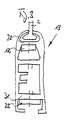
- eine Seitenansicht des erfindungsgemäßen Tores unter Weglassung der seitlichen, die Toröffnung begrenzenden Profile in schematischer Darstellung,
- Fig. 2
- einen Querschnitt des in dem Schlitz eines seitlichen Torprofils geführten Schlittens mit einem Endbereich der an diesem gehalterten Abschlußleiste des Torblattes,
- Fig. 3
- eine Draufsicht auf den Endbereich des die Abschlußleiste bildenden Profils mit den an diesem befestigten Haltestücken,
- Fig. 4
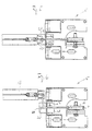
- einen Schnitt durch ein seitliches, die Toröffnung begrenzendes Profil mit in dessen vertikalem Schlitz geführtem Schlitten und an diesem gehalterten Abschlußprofil in Betriebsstellung,
- Fig. 5
- die Darstellung nach Fig. 4 in vergrößerter Darstellung und
- Fig. 6
- eine der Fig. 5 entsprechende Darstellung mit ausgeklinkter Abschlußleiste.
- Fig. 1
- 2 shows a side view of the door according to the invention, with the omission of the lateral profiles delimiting the door opening, in a schematic illustration,
- Fig. 2
- 3 shows a cross section of the slide guided in the slot of a lateral door profile with an end region of the end strip of the door leaf held thereon,
- Fig. 3
- a plan view of the end region of the profile forming the end strip with the holding pieces attached to it,
- Fig. 4
- FIG. 2 shows a section through a side profile that delimits the gate opening with a slide guided in its vertical slot and an end profile held in this in the operating position,
- Fig. 5
- 4 in an enlarged view and
- Fig. 6
- a representation corresponding to FIG. 5 with a notched end strip.
Das erfindungsgemäße Rolltor besteht aus einer in üblicher Weise
oberhalb der Toröffnung gelagerten Wickelwelle mit deren Durchmesser
vergrößerndem Wickelzylinder 1, auf den das flexible Torblatt
2 aufwickelbar ist. Auf der Wickelwelle ist im Bereich der
die Toröffnung seitlich begrenzenden Profile, von denen in den
Figuren 2 und 4 bis 5 das rechte Profil 5 dargestellt ist, eine
Wickeltrommel 3 befestigt, auf die mit zu dem Torblatt 2 entgegengesetztem
Wickelsinn ein Spannseil 4 aufwickelbar ist. Jedes
der beiden Spannseile 4 läuft von der Wickeltrommel 3 über zwei
rahmenfest gelagerte bzw. in den Seitenprofilen 5 gelagerte Umlenkrollen
6, 7 und eine zwischen diesen angeordnete Rolle 8 einer
Unterflasche über eine an dem Bodenblech 9 gelagerte Umlenkrolle
10 zu seinem Festpunkt 11 an dem oberen Haltestück 12, das
an der an dem unteren Rand des Torblatts 2 angeordneten Abschlußleiste
13 befestigt ist. An einer Öse oder einem Haken der die
Umlenkrolle 8 tragenden Unterflasche ist das obere Ende einer
Zugfeder 14 befestigt, deren unteres Ende an einer Lasche 15 befestigt
ist, die mit der Achse 16 der Umlenkrolle 10 verbunden
ist.The roller door according to the invention consists of a in the usual way
winding shaft with its diameter mounted above the gate opening
magnifying winding cylinder 1 on which the
Die Wickelwelle bzw. der Wickelzylinder 1 für das Torblatt 2 ist
durch ein Gegengewicht, dessen Gurt oder Halteseil auf eine auf
der Wickelwelle befestigte Trommel aufgewickelt ist oder durch
eine Zugfeder im Aufwickelsinn mit einem Ausgleichsmoment
beaufschlagt, das jedoch unter Berücksichtigung des von dem
Spannseil auf die Wickelwelle ausgeübten Moments so groß ist,
daß das Torblatt ganz oder teilweise auf den Wickelzylinder aufgewickelt
wird, wenn im Falle eines Stromausfalls die Bremse des
Antriebsmotors gelüftet wird.The winding shaft or the winding cylinder 1 for the
Jedes der seitlichen Profile 5 des Torrahmens weist in seiner
zur Tormitte hin weisenden Fläche einen vertikal verlaufenden
Schlitz 18 auf, der von den Stegen 19, 20 des Profils 5 begrenzt
wird. In diesem Schlitz ist schlittenartig ein etwa quaderförmiger
Klotz 21 aus Kunststoff mit niedrigem Reibungskoeffizienten
geführt, der auf gegenüberliegenden Seiten mit Nuten 22, 23 versehen
ist, in die die Stege 19, 20 des Seitenprofils 5 greifen.
Der Klotz 21 ist in seiner vertikalen Mittelebene mit einem
Spalt 24 versehen, der durch zwei scheibenartige Verbindungsstücke
25, 26 überbrückt wird, die die beiden ebenfalls etwa quaderförmigen
Halteteile 27, 28 des Klotzes 21 miteinander verbinden.
Die scheibenartigen Verbindungsstücke 25, 26 sind in der
aus Fig. 2 ersichtlichen Weise etwa diagonal zu den rechteckigen
oder quadratischen, den Spalt 24 begrenzenden Wänden des Klotzes
21 angeordnet.Each of the side profiles 5 of the goal frame has in its
a surface pointing towards the center of the
An den Querstegen 30, 31 des mit dem unteren Rand des Torblattes
2 verbundenen Abschlußprofils 13 sind die Haltestücke 12, 32,
die aus flachen Profilstücken bestehen und die Enden der Leiste
oder des Abschlußprofils 13 in der aus Fig. 2 ersichtlichen Weise
gabelförmig überragen, durch Schrauben befestigt. In der aus
Fig. 5 ersichtlichen Betriebsstellung fassen die das Abschlußprofil
13 überragenden Haltestücke 12, 32 den den Führungsschlitz
18 überragenden Teil des Klotzes 21 gabelförmig zwischen sich
ein. Dabei ist in der Betriebsstellung ein seitliches Abrutschen
der Haltestücke 12, 32 von dem Klotz 21 dadurch vermieden, daß
sich das Spannseil 4 haltend und zentrierend an den den Spalt 24
begrenzenden, inneren Seitenwandungen des Klotzes 21 anlegt.
Wirkt jedoch auf das Torblatt oder unmittelbar auf das Abschlußprofil
13 beispielsweise im Falle eines Crash eine unzulässig
hohe Querkraft, klinkt das Abschlußprofil 13 dadurch von dem Führungsblock
21 aus, daß die Haltestücke 12, 32 von diesem in der
aus Fig. 6 ersichtlichen Weise unter Mitnahme des Spannseils 4
weggedrückt werden. Dabei rutscht das Seil 4 über die obere, abgerundete
Kante des Spalts 24 in der aus den Figuren 2 und 6 ersichtlichen
Weise, ohne dabei mit den den Führungsspalt 18 begrenzenden
Profilstegen in Verbindung zu kommen. Da das Abschieben
und Wegdrücken des Abschlußprofils 13 von dem Führungsblock
21 unter der Spannung des Spannseils 4, das mit dem oberen Haltestück
12 verbunden bleibt, erfolgt, ist das Abschlußprofil durch
die Spannseile gefesselt und wird nach Beendigung der Querkraft
wieder an den Klotz herangezogen, so daß die Haltestücke mühelos
durch Aufschieben auf den Klotz 21 wieder eingeklinkt werden können.On the
Das untere Haltestück 32 kann aus elastischem Material bestehen,
so daß nach einem Ausklinken des Abschlußprofils 13 ein selbsttätiges
Einklinken dadurch erfolgen kann, daß das Tor in Richtung
auf seine Schließstellung gefahren wird. Dabei legt sich die obere
Kante des Klotzes 21 gegen die untere Außenseite des flexiblen
Haltestücks 32 in der Weise an, daß dieses nach oben gebogen
wird, bis der Halteklotz 21 in seine Betriebsstellung schnappend
über dieses hinwegrutscht. Hierzu kann das untere Haltestück entsprechend
kürzer ausgebildet sein, wobei ein entsprechendes
Spiel des Halteklotzes zwischen den Haltestücken 12, 32 vorgesehen
wird.The
Claims (10)
- Roller door having a flexible door leaf (2) which can be wound onto a drivable winding shaft (1) which is rotatably mounted above the door opening and on which a compensation torque acts to compensate the weight of the door leaf hanging down, having a batten (13) which is attached to the lower end of the door leaf (2) and whose two ends are provided with holding pieces (12, 32) to which cables (4) are attached, which cables run over rollers (10) mounted in the bottom region and tension the door leaf (2), and having side parts (5) which laterally bound the door opening, consist of profiles, and have vertical slots (18) into which the side edges of the door leaf (2) project, characterized in that the holding pieces (12, 32) do not project into the side parts (5).
- Roller door according to Claim 1, characterized in that a slide (32) is guided so as to be vertically displaceable in each of the side parts (5), which slide is fastened at its holding parts (27, 28), which project over the side parts (5) towards the middle of the door, between upper and lower holding pieces (12, 32), connected in each case to one end of the batten (13), in such a way that the holding pieces (12, 32) can only slip out or become disconnected from the holding part in the lateral direction, and in that each tensioning cable (4) is connected to an upper end region of the batten (13) and runs through a duct or gap (24) in the slide (21) to the bottom-side deflection roller (10).
- Roller door according to Claim 1 or 2, characterized in that each slide (21) has an upper and a lower stop face, which stop faces are fastened by the holding pieces (12, 32).
- Roller door according to one of Claims 1 to 3, characterized in that the slide consists of a block (21) provided with mutually parallel grooves (22, 23) on opposite sides, and in that the grooves (22, 23) engage over the profiled webs (19, 20) which bound the slot (18).
- Roller door according to one of Claims 1 to 4, characterized in that, in the plane of the door leaf (2), the block (21) is provided with a gap (24) which is bridged by two disc-like connecting pieces (25, 26) or two spindles bearing rollers.
- Roller door according to one of Claims 1 to 5, characterized in that the connecting pieces (25, 26) or spindles are arranged on corner regions, located approximately diagonally opposite one another, of approximately square or rectangular walls, bounding the gap (24), of the essentially cuboid block (21).
- Roller door according to one of Claims 1 to 6, characterized in that the holding pieces (12, 32) consist of mutually parallel, flat profiled pieces which are connected in a fork-like manner to the batten (13).
- Roller door according to one of Claims 1 to 7, characterized in that the tensioning cable (4) is connected in each case to the upper, flat profiled piece (12).
- Roller door according to one of Claims 1 to 8, characterized in that the lower, flat profiled piece (32) consists of elastic material.
- Roller door according to one of Claims 1 to 9, characterized in that each tensioning cable (4) can be wound onto and unwound from a drum (3) connected to the winding shaft (1), in a direction counter to the door leaf (2); and in that, between the bottom-side deflection roller (10) and the drum (3), the tensioning cable (4) is reeved in the manner of a pulley block between two deflection rollers (6, 7) mounted fixed to the frame and the roller (8) of a bottom pulley which is arranged between them and is tensioned by a tension spring (14) in relation to the bottom region.
Applications Claiming Priority (4)
| Application Number | Priority Date | Filing Date | Title |
|---|---|---|---|
| DE4410770 | 1994-03-28 | ||
| DE4410770 | 1994-03-28 | ||
| DE4414524 | 1994-04-26 | ||
| DE4414524A DE4414524C2 (en) | 1994-03-28 | 1994-04-26 | Roller door with a flexible door leaf |
Publications (2)
| Publication Number | Publication Date |
|---|---|
| EP0675261A1 EP0675261A1 (en) | 1995-10-04 |
| EP0675261B1 true EP0675261B1 (en) | 1998-05-06 |
Family
ID=25935163
Family Applications (1)
| Application Number | Title | Priority Date | Filing Date |
|---|---|---|---|
| EP19950102452 Expired - Lifetime EP0675261B1 (en) | 1994-03-28 | 1995-02-21 | Roller door with flexible door leaf |
Country Status (3)
| Country | Link |
|---|---|
| EP (1) | EP0675261B1 (en) |
| DE (1) | DE4447598C1 (en) |
| ES (1) | ES2115279T3 (en) |
Families Citing this family (5)
| Publication number | Priority date | Publication date | Assignee | Title |
|---|---|---|---|---|
| DE29714616U1 (en) * | 1997-08-14 | 1997-11-20 | Schieffer Tor Und Schutzsystem | Roller door with a flexible door leaf |
| DE29716966U1 (en) | 1997-09-22 | 1997-11-13 | Schieffer Tor Und Schutzsystem | Roller door with a flexible door leaf |
| JP4509664B2 (en) * | 2003-07-30 | 2010-07-21 | 株式会社東芝 | Steam turbine power generation equipment |
| DE102012111611A1 (en) * | 2012-11-29 | 2014-06-05 | Efaflex Inzeniring D.O.O. | Roller shutter with a door leaf in the form of a flexible curtain |
| CN110306916A (en) * | 2019-07-25 | 2019-10-08 | 东莞柏翠科门窗家具有限公司 | A kind of shutter door |
Family Cites Families (5)
| Publication number | Priority date | Publication date | Assignee | Title |
|---|---|---|---|---|
| DE3429781A1 (en) * | 1984-04-02 | 1985-10-10 | Schieffer GmbH & Co KG, 4780 Lippstadt | ROLLING DOOR WITH A FLEXIBLE DOOR LEAF |
| US5141044A (en) * | 1991-01-25 | 1992-08-25 | Asi Technologies, Inc. | Breakaway roll-up door |
| US5139074A (en) * | 1991-04-03 | 1992-08-18 | Kelley Company Inc. | Industrial door having flexible and releasable beam |
| DE4242430C2 (en) * | 1991-12-23 | 1995-01-05 | Norbert Lamsfuss | rolling gate |
| US5222541A (en) * | 1992-07-22 | 1993-06-29 | Kelley Company, Inc. | Industrial door having releasable beam and tension bracket retention mechanism |
-
1994
- 1994-04-26 DE DE4447598A patent/DE4447598C1/en not_active Expired - Fee Related
-
1995
- 1995-02-21 ES ES95102452T patent/ES2115279T3/en not_active Expired - Lifetime
- 1995-02-21 EP EP19950102452 patent/EP0675261B1/en not_active Expired - Lifetime
Also Published As
| Publication number | Publication date |
|---|---|
| EP0675261A1 (en) | 1995-10-04 |
| ES2115279T3 (en) | 1998-06-16 |
| DE4447598C1 (en) | 1997-03-06 |
Similar Documents
| Publication | Publication Date | Title |
|---|---|---|
| DE2341328C3 (en) | rolling gate | |
| DE3241924C2 (en) | Device for guiding flexible supply lines | |
| EP0701649B1 (en) | Cable pull window winder | |
| DE3905224A1 (en) | ROLLING GATE | |
| EP0172351B1 (en) | Safety catch | |
| WO1999015754A1 (en) | Rolling door with a flexible door leaf | |
| EP2925947A1 (en) | Roller shutter having a door leaf in the form of a flexible curtain | |
| DE3843917C2 (en) | ||
| DE4007280A1 (en) | Overload protection for flexible door - consists of bar with lugs which bend or break under excessive load | |
| DE4006212C2 (en) | louvre | |
| EP0675261B1 (en) | Roller door with flexible door leaf | |
| DE4024666A1 (en) | VErtically sliding sectional door - has cable attached to each side of door with free ends of cables joining together | |
| EP0899413A1 (en) | Roller shutter, in particular for a slope | |
| DE19949329C2 (en) | speed door | |
| CH635164A5 (en) | RAFFSTORE. | |
| DE4414524C2 (en) | Roller door with a flexible door leaf | |
| EP1031698A2 (en) | Gate | |
| DE3526745C2 (en) | ||
| EP1366259B1 (en) | Sectional door | |
| DE3741744C2 (en) | Door with a door leaf that can be moved in the side guides | |
| DE19600949C2 (en) | Roller shutters for windows or doors | |
| DE2853460C2 (en) | Winding device for moving a carrier tape for an advertising or display item | |
| DE10236869A1 (en) | Gathered blind has winding rollers for draw cords and turning rollers for adjusting incline and with inclined flanks above coupling band guide which diverts ends of coupling bands into desired plane | |
| CH653095A5 (en) | Gatherable lamellar blind with an arrangement for approximately horizontal alignment of the lowest lamella | |
| DE2917023B2 (en) | Cable hoist with gate hanger and built-in slack rope safety device for a ceiling link or roller door |
Legal Events
| Date | Code | Title | Description |
|---|---|---|---|
| PUAI | Public reference made under article 153(3) epc to a published international application that has entered the european phase |
Free format text: ORIGINAL CODE: 0009012 |
|
| AK | Designated contracting states |
Kind code of ref document: A1 Designated state(s): BE DE ES FR GB IT NL |
|
| 17P | Request for examination filed |
Effective date: 19951116 |
|
| 17Q | First examination report despatched |
Effective date: 19970430 |
|
| RAP1 | Party data changed (applicant data changed or rights of an application transferred) |
Owner name: SCHIEFFER TOR- UND SCHUTZSYSTEME GMBH |
|
| GRAG | Despatch of communication of intention to grant |
Free format text: ORIGINAL CODE: EPIDOS AGRA |
|
| GRAG | Despatch of communication of intention to grant |
Free format text: ORIGINAL CODE: EPIDOS AGRA |
|
| GRAH | Despatch of communication of intention to grant a patent |
Free format text: ORIGINAL CODE: EPIDOS IGRA |
|
| GRAH | Despatch of communication of intention to grant a patent |
Free format text: ORIGINAL CODE: EPIDOS IGRA |
|
| GRAA | (expected) grant |
Free format text: ORIGINAL CODE: 0009210 |
|
| AK | Designated contracting states |
Kind code of ref document: B1 Designated state(s): BE DE ES FR GB IT NL |
|
| REF | Corresponds to: |
Ref document number: 59502082 Country of ref document: DE Date of ref document: 19980610 |
|
| REG | Reference to a national code |
Ref country code: ES Ref legal event code: FG2A Ref document number: 2115279 Country of ref document: ES Kind code of ref document: T3 |
|
| GBT | Gb: translation of ep patent filed (gb section 77(6)(a)/1977) |
Effective date: 19980616 |
|
| ITF | It: translation for a ep patent filed |
Owner name: BUGNION S.P.A. |
|
| ET | Fr: translation filed | ||
| PLBE | No opposition filed within time limit |
Free format text: ORIGINAL CODE: 0009261 |
|
| STAA | Information on the status of an ep patent application or granted ep patent |
Free format text: STATUS: NO OPPOSITION FILED WITHIN TIME LIMIT |
|
| 26N | No opposition filed | ||
| REG | Reference to a national code |
Ref country code: GB Ref legal event code: IF02 |
|
| PGFP | Annual fee paid to national office [announced via postgrant information from national office to epo] |
Ref country code: NL Payment date: 20140208 Year of fee payment: 20 |
|
| PGFP | Annual fee paid to national office [announced via postgrant information from national office to epo] |
Ref country code: FR Payment date: 20140211 Year of fee payment: 20 Ref country code: ES Payment date: 20140113 Year of fee payment: 20 Ref country code: IT Payment date: 20140109 Year of fee payment: 20 Ref country code: BE Payment date: 20140214 Year of fee payment: 20 |
|
| PGFP | Annual fee paid to national office [announced via postgrant information from national office to epo] |
Ref country code: GB Payment date: 20140219 Year of fee payment: 20 |
|
| PGFP | Annual fee paid to national office [announced via postgrant information from national office to epo] |
Ref country code: DE Payment date: 20140417 Year of fee payment: 20 |
|
| REG | Reference to a national code |
Ref country code: DE Ref legal event code: R071 Ref document number: 59502082 Country of ref document: DE |
|
| REG | Reference to a national code |
Ref country code: DE Ref legal event code: R071 Ref document number: 59502082 Country of ref document: DE |
|
| REG | Reference to a national code |
Ref country code: NL Ref legal event code: V4 Effective date: 20150221 |
|
| REG | Reference to a national code |
Ref country code: GB Ref legal event code: PE20 Expiry date: 20150220 |
|
| REG | Reference to a national code |
Ref country code: ES Ref legal event code: FD2A Effective date: 20150428 |
|
| PG25 | Lapsed in a contracting state [announced via postgrant information from national office to epo] |
Ref country code: GB Free format text: LAPSE BECAUSE OF EXPIRATION OF PROTECTION Effective date: 20150220 |
|
| PG25 | Lapsed in a contracting state [announced via postgrant information from national office to epo] |
Ref country code: ES Free format text: LAPSE BECAUSE OF EXPIRATION OF PROTECTION Effective date: 20150222 |