EP0899413A1 - Roller shutter, in particular for a slope - Google Patents
Roller shutter, in particular for a slope Download PDFInfo
- Publication number
- EP0899413A1 EP0899413A1 EP98113859A EP98113859A EP0899413A1 EP 0899413 A1 EP0899413 A1 EP 0899413A1 EP 98113859 A EP98113859 A EP 98113859A EP 98113859 A EP98113859 A EP 98113859A EP 0899413 A1 EP0899413 A1 EP 0899413A1
- Authority
- EP
- European Patent Office
- Prior art keywords
- roller shutter
- arrangement according
- pull rope
- shutter curtain
- roller
- Prior art date
- Legal status (The legal status is an assumption and is not a legal conclusion. Google has not performed a legal analysis and makes no representation as to the accuracy of the status listed.)
- Withdrawn
Links
- 238000004804 winding Methods 0.000 claims description 16
- 241000446313 Lamella Species 0.000 claims description 9
- 238000000034 method Methods 0.000 claims description 5
- 230000003319 supportive effect Effects 0.000 claims description 2
- 230000005484 gravity Effects 0.000 description 4
- 230000000694 effects Effects 0.000 description 3
- 230000008878 coupling Effects 0.000 description 1
- 238000010168 coupling process Methods 0.000 description 1
- 238000005859 coupling reaction Methods 0.000 description 1
- 238000011161 development Methods 0.000 description 1
- 230000018109 developmental process Effects 0.000 description 1
- 230000003287 optical effect Effects 0.000 description 1
- 238000012800 visualization Methods 0.000 description 1
Images
Classifications
-
- E—FIXED CONSTRUCTIONS
- E06—DOORS, WINDOWS, SHUTTERS, OR ROLLER BLINDS IN GENERAL; LADDERS
- E06B—FIXED OR MOVABLE CLOSURES FOR OPENINGS IN BUILDINGS, VEHICLES, FENCES OR LIKE ENCLOSURES IN GENERAL, e.g. DOORS, WINDOWS, BLINDS, GATES
- E06B9/00—Screening or protective devices for wall or similar openings, with or without operating or securing mechanisms; Closures of similar construction
- E06B9/56—Operating, guiding or securing devices or arrangements for roll-type closures; Spring drums; Tape drums; Counterweighting arrangements therefor
- E06B9/92—Means allowing the closures to be shifted out of the plane of the opening
-
- E—FIXED CONSTRUCTIONS
- E06—DOORS, WINDOWS, SHUTTERS, OR ROLLER BLINDS IN GENERAL; LADDERS
- E06B—FIXED OR MOVABLE CLOSURES FOR OPENINGS IN BUILDINGS, VEHICLES, FENCES OR LIKE ENCLOSURES IN GENERAL, e.g. DOORS, WINDOWS, BLINDS, GATES
- E06B9/00—Screening or protective devices for wall or similar openings, with or without operating or securing mechanisms; Closures of similar construction
- E06B9/56—Operating, guiding or securing devices or arrangements for roll-type closures; Spring drums; Tape drums; Counterweighting arrangements therefor
- E06B9/68—Operating devices or mechanisms, e.g. with electric drive
Definitions
- the invention relates to a roller shutter arrangement, in particular for diagonally arranged roller shutter surfaces, with one Roller shutter armor guided in lateral guide rails, that on a winding shaft at an end region of the roller shutter surface can be wound up and unwound.
- roller shutter arrangements are available in a variety of designs known.
- the weight of the Roller shutter curtain generally does the unwinding process to be carried out automatically, i.e. the roller shutter curtain is done by manual or motorized turning the winding shaft is wound, and winds when released it automatically turns off due to gravity.
- roller shutter surface The more inclined the roller shutter surface is, the less becomes the action of gravity, and the more increases the friction effect, so that, for example automatic unwinding at a certain inclination is more possible.
- Arrangements are already known where the unwinding process using pulling ropes is carried out, which is also driven by the drive motor , however, require such drive arrangements relatively complex and expensive freewheel and clutch devices.
- An object of the present invention is to create a roller shutter arrangement in the simple and inexpensive way of unwinding the roller shutter curtain is guaranteed even without the action of gravity.
- the roller shutter curtain required force by the elastic force of the provided at least one pulling rope that is tensions when winding, that is, the winding process takes place against the force of this elastic pull rope.
- There just one elastic pull rope or two elastic ones Towing ropes are required can be a very inexpensive Solution can be realized that neither coupling devices still needs freewheel devices and that Unwinding the roller shutter regardless of the angular position of the Roller shutter area guaranteed.
- the end of the at least not attacking the roller shutter curtain a pull rope only needs to be on the roller shutter arrangement or a building provided with it be fixed.
- this is at least a pulley deflected by 180 °. By if necessary several deflections can be the desired length of the Rope can be reached.
- the at least one pulley is arranged on or in the guide rails so that they does not appear visually.
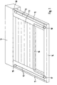
- FIGS. 1 and 2 is a roller shutter curtain consisting of individual slats 10 guided on two lateral guide rails 11, 12, each with one end on a roller shutter box 13 open into the, in a not shown, but known Way a winding shaft for winding the roller shutter curtain 10 is rotatably mounted.
- This winding shaft can also be used an electric drive motor for winding up the roller shutter curtain 10 be provided.
- the opposite End regions of the guide rails 11, 12 are over a connecting bar 14 connected to each other, the End stop for the roller shutter curtain 10 in the unwound state represents.
- An elastic pull rope 15 runs through the end slat 16 at the free end area of the roller shutter curtain 10. Of the lateral end portions of this end lamella 16 extends the elastic pull rope 15 in the unwinding direction and is at the end areas removed from the roller shutter box 13 the connecting bar 14 by pulleys 17, 18 through 180 ° redirected.
- the elastic pull rope runs from these 15 each in the guide rails 11, 12 to the roller shutter box 13, is replaced by two shortly before this Deflection rollers 19, 20 are deflected by 180 ° and run from there again through the guide rails 11, 12 back to their end areas removed from the roller shutter box 13. There are the two ends of the pull rope 15 by means of fastening devices 21 on the guide rails 11, 12 fixed.
- the deflection rollers are 17 - 20 and the pull rope 15 within the guide rails 11, 12 arranged or guided so that an optical Coverage is achieved.
- the deflection rollers 17 - 20 outside the guide rails 11, 12 to arrange and also the pull rope 15 outside of Guide rails 11, 12 to guide.
- the elastic traction rope 15 can also on this end slat 16 via two further deflection rollers, not shown be led.
- the elastic pull rope 15 in the version shown also achieved the desired balance of power become.
- two pull cables can also be used be provided at the two end regions of the end lamella 16 are attached.
- a length adjustment device for at least one of the traction ropes prove to be useful to balance the forces to adjust.
- only one only pull rope can be provided, for example can be fixed in the middle of the end lamella 16, provided the central guidance of such a pull rope is not there proves to be annoying.
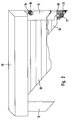
- the one shown in Fig. 2 oblique roller shutter curtain, the end lamella 16 is very short, and here is a single side pull rope 15 as sufficient.
- the principle is essential in all embodiments Effect of the shutter arrangement according to the invention, namely when winding up the roller shutter curtain 10 in the roller shutter box 13 a pull rope is tightened more and more, so that when unwinding the elastic force of this pull rope or this pulling rope acts in the unwinding direction and unwinding guaranteed regardless of gravity is.
Landscapes
- Engineering & Computer Science (AREA)
- Structural Engineering (AREA)
- Architecture (AREA)
- Civil Engineering (AREA)
- Operating, Guiding And Securing Of Roll- Type Closing Members (AREA)
Abstract
Description
Die Erfindung betrifft eine Rolladenanordnung, insbesondere für schräg angeordnete Rolladenflächen, mit einem in seitlichen Führungsschienen geführten Rolladenpanzer, der auf einer Wickelwelle an einem Endbereich der Rollladenfläche auf- und abwickelbar ist.The invention relates to a roller shutter arrangement, in particular for diagonally arranged roller shutter surfaces, with one Roller shutter armor guided in lateral guide rails, that on a winding shaft at an end region of the roller shutter surface can be wound up and unwound.
Derartige Rolladenanordnungen sind in vielfältigen Ausführungen bekannt. Beispielsweise bei vertikalen Rolladenanordnungen, bei denen die Wickelwelle oberhalb der Rollladenfläche angeordnet ist, reicht die Gewichtskraft des Rolladenpanzers im allgemeinen dazu aus, den Abwickelvorgang selbsttätig durchzuführen, das heißt, der Rollladenpanzer wird durch manuelles oder motorisches Drehen der Wickelwelle aufgewickelt, und beim Loslassen wickelt er sich automatisch schwerkraftbedingt wieder ab.Such roller shutter arrangements are available in a variety of designs known. For example with vertical roller shutter arrangements, where the winding shaft above the roller shutter surface is arranged, the weight of the Roller shutter curtain generally does the unwinding process to be carried out automatically, i.e. the roller shutter curtain is done by manual or motorized turning the winding shaft is wound, and winds when released it automatically turns off due to gravity.
Je schräger die Rolladenfläche angeordnet ist, desto geringer wird die Einwirkung der Schwerkraft, und desto mehr erhöht sich die Reibungswirkung, so daß beispielsweise ab einer bestimmten Neigung ein selbsttätiges Abwickeln nicht mehr möglich ist. Es sind zwar bereits Anordnungen bekannt, bei denen der Abwickelvorgang mittels Zugseilen durchgeführt wird, die ebenfalls vom Antriebsmotor angetrieben werden, jedoch erfordern solche Antriebsanordnungen relativ aufwendige und teure Freilauf- und Kupplungseinrichtungen.The more inclined the roller shutter surface is, the less becomes the action of gravity, and the more increases the friction effect, so that, for example automatic unwinding at a certain inclination is more possible. Arrangements are already known where the unwinding process using pulling ropes is carried out, which is also driven by the drive motor , however, require such drive arrangements relatively complex and expensive freewheel and clutch devices.
Eine Aufgabe der vorliegenden Erfindung besteht darin, eine Rolladenanordnung zu schaffen, bei der auf einfache und kostengünstige Weise der Abwickelvorgang des Rolladenpanzers auch ohne Schwerkrafteinwirkung gewährleistet ist.An object of the present invention is to create a roller shutter arrangement in the simple and inexpensive way of unwinding the roller shutter curtain is guaranteed even without the action of gravity.
Diese Aufgabe wird erfindungsgemäß dadurch gelöst, daß wenigstens ein am freien Endbereich des Rolladenpanzers angreifendes elastisches Zugseil vorgesehen ist, das beim Aufwickeln des Rolladenpanzers auf die Wickelwelle gespannt wird und beim Abwickeln eine den Abwickelvorgang unterstützende elastische Kraft zur Verfügung stellt.This object is achieved in that at least one at the free end area of the roller shutter curtain Attacking elastic pull rope is provided, which at Winding the roller shutter curtain tensioned on the winding shaft will and when unwinding the unwinding process provides supportive elastic force.
Erfindungsgemäß wird daher die zum Abwickeln des Rolladenpanzers erforderliche Kraft durch die elastische Kraft des wenigstens einen Zugseils zur Verfügung gestellt, das sich beim Aufwickeln spannt, das heißt, der Aufwickelvorgang erfolgt gegen die Kraft dieses elastischen Zugseils. Da hierfür lediglich ein elastisches Zugseil oder zwei elastische Zugseile erforderlich sind, kann eine sehr kostengünstige Lösung realisiert werden, die weder Kupplungseinrichtungen noch Freilaufeinrichtungen benötigt und die das Abwickeln des Rolladens unabhängig von der Winkellage der Rolladenfläche gewährleistet.According to the invention, therefore, is used for unwinding the roller shutter curtain required force by the elastic force of the provided at least one pulling rope that is tensions when winding, that is, the winding process takes place against the force of this elastic pull rope. There just one elastic pull rope or two elastic ones Towing ropes are required can be a very inexpensive Solution can be realized that neither coupling devices still needs freewheel devices and that Unwinding the roller shutter regardless of the angular position of the Roller shutter area guaranteed.
Durch die in den Unteransprüchen aufgeführten Maßnahmen sind vorteilhafte Weiterbildungen und Verbesserungen der im Anspruch 1 angegebenen Rolladenanordnung möglich.By the measures listed in the subclaims are advantageous developments and improvements of roller shutter arrangement specified in claim 1 possible.
Um zum einen zu verhindern, daß das elastische Zugseil optisch störend oder bei der Handhabung hinderlich in Erscheinung tritt, und um andererseits eine gleichmäßige Abwickelkraft zur Verfügung zu stellen, greifen in vorteilhafter Weise zwei Zugseile an den seitlichen Endbereichen des Rolladenpanzers an. Diese sind zweckmäßigerweise in oder an den Führungsschienen geführt, so daß sie optisch nicht in Erscheinung treten bzw. verdeckt sind.On the one hand to prevent the elastic pull rope optically distracting or obstructing handling Appearance occurs, and on the other hand an even Providing unwinding force is more advantageous Way two pull ropes on the side end areas of the roller shutter curtain. These are useful guided in or on the guide rails so that they do not appear visually or are hidden.
Das nicht am Rolladenpanzer angreifende Endes des wenigstens einen Zugseils braucht lediglich an der Rolladenanordnung oder einem damit versehenen Gebäude ortsfest fixiert werden.The end of the at least not attacking the roller shutter curtain a pull rope only needs to be on the roller shutter arrangement or a building provided with it be fixed.
Zur Erzielung der erforderlichen expansionsfähigen Länge des wenigstens einen Zugseils ist dieses über wenigstens eine Umlenkrolle um 180° umgelenkt. Durch erforderlichenfalls mehrere Umlenkungen kann so die gewünschte Länge des Zugseils erreicht werden. Die wenigstens eine Umlenkrolle ist an oder in den Führungsschienen angeordnet, damit sie optisch nicht in Erscheinung tritt.To achieve the required expandable length of the at least one pull rope, this is at least a pulley deflected by 180 °. By if necessary several deflections can be the desired length of the Rope can be reached. The at least one pulley is arranged on or in the guide rails so that they does not appear visually.
Um die Wirkung von zwei Zugseilen durch ein Zugseil zu erreichen, ist dieses parallel zur freien Endkante des Rolladenpanzers in oder an der Endlamelle geführt und erstreckt sich von den beiden Endbereichen dieser Lamelle aus in die Abwickelrichtung. Durch Verschieben dieses Zugseils kann die Kraftwirkung an den beiden Enden des Rollladenpanzers exakt eingestellt werden, wobei auch durch Umlenkrollen an der Endlamelle ein automatischer Kraftausgleich möglich ist.To the effect of two pull ropes through a pull rope reach, this is parallel to the free end edge of the Roller shutter curtain guided and extended in or on the end lamella different from the two end areas of this slat out in the unwinding direction. By moving this pull rope can apply the force at both ends of the roller shutter curtain can be set exactly, also by Deflection rollers on the end lamella provide automatic force compensation is possible.
Ein Ausführungsbeispiel der Erfindung ist in der Zeichnung dargestellt und in der nachfolgenden Beschreibung näher erläutert. Es zeigen:
- Fig. 1
- eine perspektivische Darstellung einer Rolladenanordnung mit schräg angeordneter Rolladenfläche, wobei die Führung des elastischen Zugseils schematisch dargestellt ist, und
- Fig. 2
- eine ähnliche Rolladenanordnung mit einer
schrägen Endkante des Rolladenpanzers in einer
Teildarstellung von der entgegengesetzten Seite
her,
wobei die Führungsschienen zur Sichtbarmachung des elastischen Zugseils und der Umlenkrollen zum Teil aufgeschnitten dargestellt sind.
- Fig. 1
- a perspective view of a roller shutter arrangement with an obliquely arranged roller shutter surface, wherein the guide of the elastic cable is shown schematically, and
- Fig. 2
- a similar roller shutter arrangement with an oblique end edge of the roller shutter curtain in a partial representation from the opposite side,
the guide rails for the visualization of the elastic traction cable and the deflection rollers are shown partially cut away.
Bei den in den Fig. 1 und 2 dargestellten Ausführungsbeispielen
ist ein aus einzelnen Lamellen bestehender Rolladenpanzer
10 an zwei seitlichen Führungsschienen 11, 12 geführt,
die jeweils mit einem Ende an einem Rolladenkasten
13 münden, in dem in nicht dargestellter, jedoch bekannter
Weise eine Wickelwelle zum Aufwickeln des Rolladenpanzers
10 drehbar gelagert ist. Diese Wickelwelle kann auch mit
einem elektrischen Antriebsmotor zum Aufwickeln des Rollladenpanzers
10 versehen sein. Alternativ hierzu kann auch
ein mit der Wickelwelle verbundenes Rolladenband zum manuellen
Auf- und Abwickeln vorgesehen sein. Die entgegengesetzten
Endbereiche der Führungsschienen 11, 12 sind über
eine Verbindungsleiste 14 miteinander verbunden, die den
Endanschlag für den Rolladenpanzer 10 im abgewickelten Zustand
darstellt.In the embodiments shown in FIGS. 1 and 2
is a roller shutter curtain consisting of
Ein elastisches Zugseil 15 verläuft durch die Endlamelle
16 am freien Endbereich des Rolladenpanzers 10. Von den
seitlichen Endbereichen dieser Endlamelle 16 aus erstreckt
sich das elastische Zugseil 15 in die Abwickelrichtung und
wird an den vom Rolladenkasten 13 entfernten Endbereichen
der Verbindungsleiste 14 durch Umlenkrollen 17, 18 um 180°
umgelenkt. Von diesen aus verläuft das elastische Zugseil
15 jeweils in den Führungsschienen 11, 12 zum Rolladenkasten
13 hin, wird kurz vor diesem wiederum durch zwei
Umlenkrollen 19, 20 um jeweils 180° umgelenkt und verläuft
von dort aus wieder durch die Führungsschienen 11, 12
zurück bis zu deren vom Rolladenkasten 13 entfernten Endbereichen.
Dort sind die beiden Enden des Zugseils 15
mittels Befestigungseinrichtungen 21 an den Führungsschienen
11, 12 fixiert.An
Durch diese Umlenkungen wird die benötigte expansionsfähige
Länge des Zugseils 15 erreicht, wobei die Zahl der
Umlenkungen jeweils den Erfordernissen angepaßt werden
kann.These redirections make the required expandable
Length of the
In den dargestellten Ausführungsbeispielen sind die Umlenkrollen
17 - 20 sowie das Zugseil 15 innerhalb der Führungsschienen
11, 12 angeordnet bzw. geführt, so daß eine optische
Abdeckung erreicht wird. Hierzu besitzen die
Führungsschienen 11, 12 beispielsweise getrennte Kammern
und/oder Führungskanäle für das Zugseil 15 und die Umlenkrollen
17 - 20. Es ist selbstverständlich auch möglich,
die Umlenkrollen 17 - 20 außerhalb der Führungsschienen
11, 12 anzuordnen und auch das Zugseil 15 außerhalb der
Führungsschienen 11, 12 zu führen. In the illustrated exemplary embodiments, the deflection rollers are
17 - 20 and the
Zum Kraftausgleich bzw. zur automatischen Einstellung von
gleichen Kräften an den beiden Endbereichen der Endlamelle
16 kann das elastische Zugseil 15 auch an dieser Endlamelle
16 über zwei weitere nicht dargestellte Umlenkrollen
geführt sein. Andererseits kann durch Verschieben
des elastischen Zugseils 15 in der dargestellten Version
ebenfalls das angestrebte Kräftegleichgewicht erreicht
werden.For balancing forces or for automatic adjustment of
same forces on the two end areas of the
In einer weiteren Ausgestaltung können auch zwei Zugseile
vorgesehen sein, die an den beiden Endbereichen der Endlamelle
16 befestigt sind. Bei einer solchen Ausführung
kann sich eine Längenjustiereinrichtung für wenigstens
eines der Zugseile als zweckmäßig erweisen, um das Kräftegleichgewicht
einzujustieren.In a further embodiment, two pull cables can also be used
be provided at the two end regions of the
In einer sehr einfachen Ausführungsform kann auch nur ein
einziges Zugseil vorgesehen sein, das beispielsweise auch
in der Mitte der Endlamelle 16 fixiert sein kann, sofern
die mittige Führung eines solchen Zugseils sich dort nicht
als störend erweist. Bei dem in Fig. 2 dargestellten
schrägen Rolladenpanzer ist die Endlamelle 16 sehr kurz,
und hier erweist sich ein einziges seitliches Zugseil 15
als ausreichend.In a very simple embodiment, only one
only pull rope can be provided, for example
can be fixed in the middle of the
Wesentlich bei allen Ausführungsformen ist die prinzipielle
Wirkung der erfindungsgemäßen Rolladenanordnung, daß nämlich
beim Aufwickeln des Rolladenpanzers 10 im Rolladenkasten
13 ein Zugseil immer stärker gespannt wird, so daß
beim Abwickeln die elastische Kraft dieses Zugseils oder
dieser Zugseile in die Abwickelrichtung wirkt und ein Abwickeln
unabhängig von Schwerkrafteinflüssen gewährleistet
ist.The principle is essential in all embodiments
Effect of the shutter arrangement according to the invention, namely
when winding up the
Claims (8)
Applications Claiming Priority (2)
| Application Number | Priority Date | Filing Date | Title |
|---|---|---|---|
| DE19737263A DE19737263A1 (en) | 1997-08-27 | 1997-08-27 | Roller shutter arrangement, especially for sloping roller shutter surfaces |
| DE19737263 | 1997-08-27 |
Publications (1)
| Publication Number | Publication Date |
|---|---|
| EP0899413A1 true EP0899413A1 (en) | 1999-03-03 |
Family
ID=7840287
Family Applications (1)
| Application Number | Title | Priority Date | Filing Date |
|---|---|---|---|
| EP98113859A Withdrawn EP0899413A1 (en) | 1997-08-27 | 1998-07-24 | Roller shutter, in particular for a slope |
Country Status (3)
| Country | Link |
|---|---|
| US (1) | US6079472A (en) |
| EP (1) | EP0899413A1 (en) |
| DE (1) | DE19737263A1 (en) |
Cited By (1)
| Publication number | Priority date | Publication date | Assignee | Title |
|---|---|---|---|---|
| FR2937429A1 (en) * | 2008-10-22 | 2010-04-23 | Screen Res | Side mask device for projection screen, has side mask equipped with elastic return unit along closing direction of sheet, and stiffener arranged along free internal side edge of sheet, where return unit is fixed to stiffener |
Families Citing this family (11)
| Publication number | Priority date | Publication date | Assignee | Title |
|---|---|---|---|---|
| US6378592B1 (en) | 1999-03-16 | 2002-04-30 | Stephen G. Kimmet | Security system for a cubicle |
| DE29907720U1 (en) | 1999-04-30 | 1999-08-12 | H. H. Heim und Haus Holding GmbH, 47169 Duisburg | Roller shutter arrangement for horizontally split windows |
| DE29914094U1 (en) | 1999-08-12 | 1999-10-07 | Firma Hermann Huss Rolladenbau, 72622 Nürtingen | Roller shutters with slats guided in horizontal rails |
| US6688374B2 (en) * | 2001-11-09 | 2004-02-10 | Rite-Hite Holding Corporation | Barrier with movable curtain |
| US7173514B2 (en) * | 2002-03-15 | 2007-02-06 | Wayne-Dalton Corp. | Operator for a movable barrier and method of use |
| US6796357B2 (en) * | 2002-09-30 | 2004-09-28 | Lutron Electronics Co., Inc. | Extension panel for a folding shade |
| US6796356B2 (en) * | 2002-09-30 | 2004-09-28 | Lutron Electronics Co., Inc. | Folding shades having minimal sag when folded |
| WO2006133556A1 (en) * | 2005-06-16 | 2006-12-21 | Screenline Innovations Inc. | Retractable screen door housing handle balancing system |
| DE202006017199U1 (en) * | 2006-11-10 | 2008-03-20 | SCHÜCO International KG | shutters |
| US8439098B1 (en) * | 2011-09-09 | 2013-05-14 | Brian E. Jones | Closing-biased retractable screen door system |
| DE202012101321U1 (en) * | 2012-04-12 | 2013-07-15 | Inalfa Roof Systems Group B.V. | Roller blind arrangement and provided with this open roof construction for a vehicle |
Citations (4)
| Publication number | Priority date | Publication date | Assignee | Title |
|---|---|---|---|---|
| DE2906871A1 (en) * | 1979-02-22 | 1980-09-04 | Velux Gmbh Bauzubehoer | External window blind assembly - has spirally wound leaf springs acting in closing direction on free end corners of blind |
| EP0276045A2 (en) * | 1987-01-17 | 1988-07-27 | Clark Door Limited | Improvements in and relating to roller doors |
| DE4005963A1 (en) * | 1989-03-03 | 1990-09-06 | Itw Ind Und Werkzeugmaschinen | Suspension system for roller blind-type door - has winding roller with cable and pulley systems incorporating resilient tensioning devices |
| FR2692930A1 (en) * | 1992-06-25 | 1993-12-31 | Journault Michel | Roller shutter for exterior glazed surface - has tube on which shutter is roller equipped with reel at each for cable connected to tensioner spring inside supporting bar |
Family Cites Families (10)
| Publication number | Priority date | Publication date | Assignee | Title |
|---|---|---|---|---|
| US490448A (en) * | 1893-01-24 | Flexible door | ||
| US520065A (en) * | 1894-05-22 | Flexible door | ||
| US3460602A (en) * | 1967-06-08 | 1969-08-12 | Closures Inc | Flexible closure tensioning device |
| FR2543610B1 (en) * | 1983-03-31 | 1986-04-11 | Ducos Antoine | SHUTTER FOR LOW SLOPE BAY |
| GB8700987D0 (en) * | 1987-01-17 | 1987-02-18 | Clark Door Ltd | Roller doors |
| US5141044A (en) * | 1991-01-25 | 1992-08-25 | Asi Technologies, Inc. | Breakaway roll-up door |
| JPH0797886A (en) * | 1993-08-05 | 1995-04-11 | Hayashiguchi Kogyo Kk | Screen device |
| US5477904A (en) * | 1994-05-31 | 1995-12-26 | Yang; Ming-Shun | Window curtain assembly having a tension spring retraction mechanism |
| JP3312848B2 (en) * | 1995-07-14 | 2002-08-12 | 株式会社メタコ | Screen device |
| US5566736A (en) * | 1995-11-13 | 1996-10-22 | Crider; Grant W. | Sealable curtain |
-
1997
- 1997-08-27 DE DE19737263A patent/DE19737263A1/en not_active Withdrawn
-
1998
- 1998-07-24 EP EP98113859A patent/EP0899413A1/en not_active Withdrawn
- 1998-07-31 US US09/126,774 patent/US6079472A/en not_active Expired - Fee Related
Patent Citations (4)
| Publication number | Priority date | Publication date | Assignee | Title |
|---|---|---|---|---|
| DE2906871A1 (en) * | 1979-02-22 | 1980-09-04 | Velux Gmbh Bauzubehoer | External window blind assembly - has spirally wound leaf springs acting in closing direction on free end corners of blind |
| EP0276045A2 (en) * | 1987-01-17 | 1988-07-27 | Clark Door Limited | Improvements in and relating to roller doors |
| DE4005963A1 (en) * | 1989-03-03 | 1990-09-06 | Itw Ind Und Werkzeugmaschinen | Suspension system for roller blind-type door - has winding roller with cable and pulley systems incorporating resilient tensioning devices |
| FR2692930A1 (en) * | 1992-06-25 | 1993-12-31 | Journault Michel | Roller shutter for exterior glazed surface - has tube on which shutter is roller equipped with reel at each for cable connected to tensioner spring inside supporting bar |
Cited By (1)
| Publication number | Priority date | Publication date | Assignee | Title |
|---|---|---|---|---|
| FR2937429A1 (en) * | 2008-10-22 | 2010-04-23 | Screen Res | Side mask device for projection screen, has side mask equipped with elastic return unit along closing direction of sheet, and stiffener arranged along free internal side edge of sheet, where return unit is fixed to stiffener |
Also Published As
| Publication number | Publication date |
|---|---|
| US6079472A (en) | 2000-06-27 |
| DE19737263A1 (en) | 1999-03-04 |
Similar Documents
| Publication | Publication Date | Title |
|---|---|---|
| DE2341328C3 (en) | rolling gate | |
| EP0082302B1 (en) | Solar and/or weather protection device | |
| EP1258378A2 (en) | Roller blind for transparent roof element | |
| WO1997037098A1 (en) | Door with traction cable system | |
| EP0899413A1 (en) | Roller shutter, in particular for a slope | |
| DE3520857A1 (en) | Sun canopy, which can be rolled up, for winter gardens or the like | |
| DE19610268C2 (en) | Roller blind device for an insulating glass element | |
| DE10333407A1 (en) | Flexible retractable awning or roof for covering open space has shaft used as winding spindle stretched between two posts and corners of triangular flexible sheets are held by spring-loaded cables | |
| DE3245009A1 (en) | Roller door | |
| DE3736153C2 (en) | Roller shutters for roof windows | |
| DE3843917A1 (en) | Drive device for a rolling surface | |
| DE3415551C2 (en) | Roller shutters for roof windows | |
| EP0764233A1 (en) | Window blind | |
| EP0393489B1 (en) | Cable-breakage safety device | |
| DE8703605U1 (en) | Roller blind for automotive windows, especially for car rear windows | |
| DE8813821U1 (en) | Roller shutter with winding roller arranged at the side of the door opening | |
| DE4105865A1 (en) | Dual motorised winder for roller-blind or awning - is stopped in fully retracted position by switches opened when motor mountings pivot with cables slackened | |
| EP0164047B1 (en) | Roller blind | |
| DE19707408C2 (en) | Covering device, in particular awning | |
| EP0675261B1 (en) | Roller door with flexible door leaf | |
| DE4327230C1 (en) | Roller blind for roof windows | |
| DE19852686B4 (en) | Curtain for a non-rectangular area, especially a window or opening | |
| DE9102196U1 (en) | Device for winding and unwinding curtains, in particular awning fabrics, roller shutters, grilles or the like. | |
| DE10236869A1 (en) | Gathered blind has winding rollers for draw cords and turning rollers for adjusting incline and with inclined flanks above coupling band guide which diverts ends of coupling bands into desired plane | |
| DE4100608A1 (en) | Automatic safety switch mechanism - is for electrically driven roller blinks and cuts off power when cord is over-tensioned |
Legal Events
| Date | Code | Title | Description |
|---|---|---|---|
| PUAI | Public reference made under article 153(3) epc to a published international application that has entered the european phase |
Free format text: ORIGINAL CODE: 0009012 |
|
| 17P | Request for examination filed |
Effective date: 19981207 |
|
| AK | Designated contracting states |
Kind code of ref document: A1 Designated state(s): AT CH DE LI |
|
| AX | Request for extension of the european patent |
Free format text: AL;LT;LV;MK;RO;SI |
|
| AKX | Designation fees paid |
Free format text: AT CH DE LI |
|
| STAA | Information on the status of an ep patent application or granted ep patent |
Free format text: STATUS: THE APPLICATION IS DEEMED TO BE WITHDRAWN |
|
| 18D | Application deemed to be withdrawn |
Effective date: 20020201 |