EP0172351B1 - Safety catch - Google Patents
Safety catch Download PDFInfo
- Publication number
- EP0172351B1 EP0172351B1 EP85107467A EP85107467A EP0172351B1 EP 0172351 B1 EP0172351 B1 EP 0172351B1 EP 85107467 A EP85107467 A EP 85107467A EP 85107467 A EP85107467 A EP 85107467A EP 0172351 B1 EP0172351 B1 EP 0172351B1
- Authority
- EP
- European Patent Office
- Prior art keywords
- catching
- catching member
- housing
- member housing
- door
- Prior art date
- Legal status (The legal status is an assumption and is not a legal conclusion. Google has not performed a legal analysis and makes no representation as to the accuracy of the status listed.)
- Expired
Links
Images
Classifications
-
- E—FIXED CONSTRUCTIONS
- E05—LOCKS; KEYS; WINDOW OR DOOR FITTINGS; SAFES
- E05D—HINGES OR SUSPENSION DEVICES FOR DOORS, WINDOWS OR WINGS
- E05D13/00—Accessories for sliding or lifting wings, e.g. pulleys, safety catches
- E05D13/003—Anti-dropping devices
- E05D13/006—Anti-dropping devices fixed to the wing, i.e. safety catches
-
- E—FIXED CONSTRUCTIONS
- E05—LOCKS; KEYS; WINDOW OR DOOR FITTINGS; SAFES
- E05F—DEVICES FOR MOVING WINGS INTO OPEN OR CLOSED POSITION; CHECKS FOR WINGS; WING FITTINGS NOT OTHERWISE PROVIDED FOR, CONCERNED WITH THE FUNCTIONING OF THE WING
- E05F15/00—Power-operated mechanisms for wings
-
- E—FIXED CONSTRUCTIONS
- E05—LOCKS; KEYS; WINDOW OR DOOR FITTINGS; SAFES
- E05F—DEVICES FOR MOVING WINGS INTO OPEN OR CLOSED POSITION; CHECKS FOR WINGS; WING FITTINGS NOT OTHERWISE PROVIDED FOR, CONCERNED WITH THE FUNCTIONING OF THE WING
- E05F15/00—Power-operated mechanisms for wings
- E05F15/40—Safety devices, e.g. detection of obstructions or end positions
- E05F15/41—Detection by monitoring transmitted force or torque; Safety couplings with activation dependent upon torque or force, e.g. slip couplings
-
- E—FIXED CONSTRUCTIONS
- E05—LOCKS; KEYS; WINDOW OR DOOR FITTINGS; SAFES
- E05Y—INDEXING SCHEME RELATING TO HINGES OR OTHER SUSPENSION DEVICES FOR DOORS, WINDOWS OR WINGS AND DEVICES FOR MOVING WINGS INTO OPEN OR CLOSED POSITION, CHECKS FOR WINGS AND WING FITTINGS NOT OTHERWISE PROVIDED FOR, CONCERNED WITH THE FUNCTIONING OF THE WING
- E05Y2400/00—Electronic control; Power supply; Power or signal transmission; User interfaces
- E05Y2400/80—User interfaces
- E05Y2400/85—User input means
- E05Y2400/852—Sensors
- E05Y2400/856—Actuation thereof
- E05Y2400/858—Actuation thereof by body parts
- E05Y2400/86—Actuation thereof by body parts by hand
-
- E—FIXED CONSTRUCTIONS
- E05—LOCKS; KEYS; WINDOW OR DOOR FITTINGS; SAFES
- E05Y—INDEXING SCHEME RELATING TO HINGES OR OTHER SUSPENSION DEVICES FOR DOORS, WINDOWS OR WINGS AND DEVICES FOR MOVING WINGS INTO OPEN OR CLOSED POSITION, CHECKS FOR WINGS AND WING FITTINGS NOT OTHERWISE PROVIDED FOR, CONCERNED WITH THE FUNCTIONING OF THE WING
- E05Y2900/00—Application of doors, windows, wings or fittings thereof
- E05Y2900/10—Application of doors, windows, wings or fittings thereof for buildings or parts thereof
- E05Y2900/106—Application of doors, windows, wings or fittings thereof for buildings or parts thereof for garages
Definitions
- the invention relates to a fishing gear with the features of the preamble of claim 1.
- Such gear devices which often work with catch pawls, are known in a wide variety of designs, for example from DE-A 2 735123.
- the invention has for its object to provide a fishing gear of the type mentioned that works quickly and safely, is protected against dirt and damage and in particular can also be easily maintained and checked for functionality.
- the catching device By arranging practically all parts to be moved in the course of a catching process inside a housing, the catching device is initially protected against dirt and damage, the arrangement being such that when the associated traction cable strand slackens or tears, the catching member gets into the catching position before due to its inertia, the closing leaf or door leaf moves significantly downwards.
- the spring used in this context is also located inside the housing, so it is primarily protected against the fact that its effective spring length is restricted by foreign bodies that are unwantedly stored in the spring travel.
- the catching element can be transferred from the release position to the catching position along a translational path by the spring-loaded bolt in the case of slackening of the rope.
- the catch element is designed as a catch pawl which is pivotably mounted within the housing and engages with an inclined surface seen in the longitudinal direction of the bolt on the bolt end lying inside the housing, so that the bolt pivots the pawl into the catch position outside the housing due to its spring load, as soon as the spring can work due to a broken rope or the like.
- the spring arranged between the closing leaf and the traction element strand has the advantage that accelerations of the closing leaf applied in manual operation, in particular, are transmitted in a dampened manner to the weight compensation device, so that the traction element strands, which are designed in particular as ropes, cannot jump off the cable drums. So far, a separate spring arm has been provided for this. Because the safety device designed according to the invention also fulfills this function, one can do without the spring lever which is otherwise to be provided in the same place.
- the catching device is particularly preferably designed such that the direction of movement of the catching element runs approximately perpendicular to the plane of the closing leaf, so that the catching element engages in the catching position on a catching rail which can advantageously be arranged close to the surf of the gate opening to be closed.
- a catching rail which can advantageously be arranged close to the surf of the gate opening to be closed.
- the catching member housing which moves in relation to the closing leaf when caught, is supported at least on its side facing away from the catching rail.
- the catching device basically works over the entire path that the closing sheet travels between its open position and its inclined position.
- the door leaf makes lateral movements within a certain scope. With appropriately wide catch openings, you can ensure that no jamming occurs in all these cases. You often have the need to open or close a trapped door leaf. This is done simply by reaching under and lifting the door leaf with a forklift or the like.
- the catch member can be locked in the release position for lowering, for example fixed in this position by a screw. In this way, the door leaf can be opened and closed. In the normal case, the catch member can pass through this locking opening with the help of a pin or the like can be operated particularly easily to check the functionality.
- the gear can be easily attached to building locks of the type in question.
- existing, cable-borne door leaves one simply loosens the cable attachment to the laterally protruding fastening bolts and hangs the bolts of the safety gear housing on them, while the cable end is laid in the safety gear housing and fastened there, which is preferably done on the pivot axis of the safety catch.
- the displacement of the catching element into the catching position can be used to actuate a feed current switch.
- a second movement under the force of a second spring is provided for this purpose, which works following the spring that triggers the catching element.
- rollers 3 which are embedded in a guide rail 4 are fastened to the door leaf via roller holders.
- a large number of these roller holders and rollers are available, in particular in a so-called sectional door, as is known.
- the guide rails 4 are fixed by means of brackets 5 in the area of the side edge of the building opening in a manner not shown.
- catch rails 7 are also attached, which are thus also in the area of the side building opening 6 and can support them there accordingly.
- the catch rails 7 are provided with a series of catch openings 8 which are arranged in the longitudinal direction and are relatively wide, in the present case wider than the side of a catch member housing 10 facing them, which is arranged in the narrow side area of the door leaf, such as this especially Fig. 2 reveals.
- a guide fitting 11 engages on the housing side opposite the catch rail 7, so that the catch member housing 10 with catch member in the catch position - FIG. 4 - which moves in the catch position - FIG. 4 - does not detach from the catch rail, as described later - in the event of a catch relative to the door leaf 1 along its narrow side 7 can avoid evasive.
- FIGS. 3 and 4 show - like FIGS. 3 and 4 - a bolt 12 which engages at 13 on a fastening bolt 27, 13 being an eyelet within a tab.
- This bolt 12 engages through the lower end face 17 of the housing 10 in its interior.
- a clamping sleeve 15 is passed through the upper end face 16 opposite this end face, with which the wire rope 14 serving as a traction means strand is combined to form a loop.
- FIGS. 3 and 4 clearly show the design of the catching member housing 10 and the components assigned to it.
- the housing Within its longitudinal side wall 18 facing the catch rail 7, the housing has a lateral opening 19 which lies opposite the housing side 20, on which the guide fitting 11 engages in a supporting manner.
- the swivel pawl including the pawl nose, is located within the catch member housing 10 when the catch pawl 23 is in the release position due to a sufficient tension condition in the associated rope 14, which is the normal operating situation with the rope intact, properly functioning weight balancing device and The like.
- the bolt 12 In its end region located inside the housing, the bolt 12 is provided with a head 29 which is widened in such a way that the side surfaces of the bolt head are guided on the inner walls of the housing.
- a helical compression spring 32 is provided between the inner wall of the lower end face 17 of the housing 10 and the lower surface of the head 29 opposite this, through which the bolt shaft is passed.
- a sleeve-shaped stop 33 is arranged around the helical spring, which in turn is supported at one end on the inner surface of the end face 17 and at the other end on the lower surface of the head 29 facing it. As shown in Fig. 3, the bolt 12 is in tension with the rope 14 with its head 29 in contact with the stop 33, so that the helical compression spring 32 has its greatest possible compression.
- a bevel 30 is formed which, with respect to the bevel, corresponds to the course of an inclined surface 31 against which the bevel 30 rests and which, starting from the pawl nose 24, is formed on the catch pawl in the region of the catch pawl opposite the pivot axis 22.
- This system is shown in FIG. 3 for the release position 25 of the catch.
- the head 29 presses, via its bevel 30, along the inclined surface 31 of the catch pawl 23, sliding the catch pawl in rotary motion around the pivot axis 22 with the pawl nose 24 first through the lateral opening 19, so that the pawl nose 24 into the catch opening 8 which follows next to the bottom Catch rail 7 engages, as shown in Fig. 4.
- the catch pawl 23 is thus in the catch position 26.
- the clamping sleeve 15 of the cable 14 passes through a passage opening 34 in the upper end face 16 of the housing 10, and also in a longitudinally displaceable manner.
- the rope loop located in the interior of the housing 10 engages in a thimble 35, which in turn encompasses the pivot axis 22, with a certain amount of play such that when the rope becomes slack, a compression spring 32 arranged between the inner wall of the end face 16 and the thimble 35 which engages around the cable 14 and its end returned through the sleeve 15, displaces the thimble 35 by a small distance relative to the pivot axis 22 into the interior of the housing.
- an actuator 38 of an electrical switch 39 engages with which a drive motor provided here is switched off. Since the helical compression spring 32, which comprises the bolt 12, is designed to be harder or stiffer than the compression spring 36, which encompasses the cable 14, the housing 10 first moves relative to the bolt 12, so that the catch pawl 23 moves into its catch position 26, whereupon the displacement of the thimble 35 for actuating the switch 39 takes place.
- the catch pawl 23 has on its side facing away from the catch rail 7 a threaded blind hole 41 which, in the release position 25 of the pawl 23, is aligned with a bore 42 in the housing side 20 with respect to its input opening.
- the catch pawl 23 can be held in the release position or returned to it and locked there if the door leaf is not only to be opened after a fall, the catch pawl would be like a ratchet - but should also be lockable, for example with the help of a forklift, until the defective rope or the fault causing the rope to become slack has been eliminated.
- the catch openings 8 are very wide transversely to the direction of movement of the door leaf 1, namely by a multiple of the width of the latch nose 24, so that the door can be caught safely in any possible lateral displacement movement.
- a one-sided error such as a rope break, does not cause the door to jam in such a way that it cannot be lifted.
Abstract
Description
Die Erfindung bezieht sich auf ein Fanggerät mit den Merkmalen des Oberbegriffs des Anspruches 1.The invention relates to a fishing gear with the features of the preamble of
Solche Fanggeräte, die vielfach mit Fangklinken arbeiten, sind in verschiedensten Ausführungen bekannt, so beispielsweise aus der DE-A 2 735123.Such gear devices, which often work with catch pawls, are known in a wide variety of designs, for example from DE-A 2 735123.
Von diesen Fanggeräten wird eine schnelle und zuverlässige Reaktion erwartet, wenn der jeweils zugeordnete Zugmittelstrang schlaff wird, beispielsweise weil die Gewichtsausgleichseinrichtung oder die Antriebseinrichtung ausfällt bzw. der Zugmittelstrang selbst reisst. Die bekannten Fanggeräte arbeiten jedoch vielfach zu langsam, sind zu aufwendig gebaut oder nicht sicher gegen Beschädigungen und müssen häufig gewartet werden, was zum Teil sehr schwierig ist.A fast and reliable reaction is expected from these fishing devices if the respectively assigned traction cable strand becomes slack, for example because the weight compensation device or the drive device fails or the traction cable strand itself breaks. However, the known fishing gear often works too slowly, is too expensive to build or is not safe from damage and has to be serviced frequently, which is sometimes very difficult.
Der Erfindung liegt die Aufgabe zugrunde, ein Fanggerät der eingangs genannten Art zu schaffen, das schnell und sicher arbeitet, gegen Verschmutzung und Beschädigung geschützt ist und sich insbesondere auch leicht warten und auf Funktionsfähigkeit überprüfen lässt.The invention has for its object to provide a fishing gear of the type mentioned that works quickly and safely, is protected against dirt and damage and in particular can also be easily maintained and checked for functionality.
Ausgehend von einem Fanggerät mit den Merkmalen des Oberbegriffes des Anspruches 1 wird diese Aufgabe erfindungsgemäss durch dessen kennzeichnende Merkmale gelöst.Starting from a gear with the features of the preamble of
Durch die Anordnung praktisch sämtlicher im Zuge eines Fangvorganges zu bewegende Teile im Inneren eines Gehäuses wird die Fangeinrichtung zunächst gegen Schmutz und Beschädigung bewahrt, die Anordnung ist dabei so getroffen, dass bei Erschlaffen des zugeordneten Zugmittelstranges oder dessen Reissen das Fangglied in die Fangstellung gerät, bevor sich das Verschlussblatt oder Torblatt aufgrund seiner Massenträgheit nennenswert abwärts bewegt. Die in diesem Zusammenhang eingesetzte Feder befindet sich ebenfalls innerhalb des Gehäuses, sie ist damit vor allem auch dagegen geschützt, dass ihre wirksame Federlänge durch ungewollt in den Federweg eingelagerte Fremdkörper eingeschränkt wird.By arranging practically all parts to be moved in the course of a catching process inside a housing, the catching device is initially protected against dirt and damage, the arrangement being such that when the associated traction cable strand slackens or tears, the catching member gets into the catching position before due to its inertia, the closing leaf or door leaf moves significantly downwards. The spring used in this context is also located inside the housing, so it is primarily protected against the fact that its effective spring length is restricted by foreign bodies that are unwantedly stored in the spring travel.
Das Fangglied kann grundsätzlich entlang einer translatorischen Strecke durch den federbelasteten Bolzen im Falle der Seilerschlaffung von der Freigabestellung in die Fangstellung überführt werden. In besonders bevorzugter Weise ist das Fangglied als verschwenkbar innerhalb des Gehäuses gelagerte Fangklinke ausgebildet, die mit einer in Bolzenlängsrichtung gesehenen Schrägfläche an dem innerhalb des Gehäuses liegenden Bolzenende eingreift, so dass der Bolzen aufgrund seiner Federbelastung die Klinke nach ausserhalb des Gehäuses in die Fangstellung verschwenkt, sobald die Feder aufgrund eines Seilbruches oder dgl. arbeiten kann.In principle, the catching element can be transferred from the release position to the catching position along a translational path by the spring-loaded bolt in the case of slackening of the rope. In a particularly preferred manner, the catch element is designed as a catch pawl which is pivotably mounted within the housing and engages with an inclined surface seen in the longitudinal direction of the bolt on the bolt end lying inside the housing, so that the bolt pivots the pawl into the catch position outside the housing due to its spring load, as soon as the spring can work due to a broken rope or the like.
Die zwischen dem Verschlussblatt und dem Zugmittelstrang angeordnete Feder hat noch den Vorteil, dass insbesondere bei Handbetätigung aufgebrachte Beschleunigungen des Verschlussblattes gedämpft auf die Gewichtsausgleichseinrichtung übertragen werden, so dass die Zugmittelstränge, die insbesondere als Seile ausgebildet sind, nicht von den Seiltrommeln springen können. Hierzu hat man bislang einen gesonderten Federarm vorgesehen. Dadurch dass die erfindungsgemäss ausgebildete Fangeinrichtung diese Wirkungsfunktion miterfüllt, kann man auf den sonst an gleichem Platz vorzusehenden Federhebel verzichten.The spring arranged between the closing leaf and the traction element strand has the advantage that accelerations of the closing leaf applied in manual operation, in particular, are transmitted in a dampened manner to the weight compensation device, so that the traction element strands, which are designed in particular as ropes, cannot jump off the cable drums. So far, a separate spring arm has been provided for this. Because the safety device designed according to the invention also fulfills this function, one can do without the spring lever which is otherwise to be provided in the same place.
Das Fanggerät ist besonders bevorzugt derart ausgebildet, dass die Bewegungsrichtung des Fanggliedes etwa senkrecht zur Verschlussblattebene verläuft, so dass das Fangglied in der Fangstellung an einer Fangschiene angreift, die vorteilhaft nahe an der Brandung der zur verschliessenden Toröffnung angeordnet werden kann. Dadurch lassen sich die beim Fangen auftretenden, unter Umständen erheblichen Kräfte gut in das Mauerwerk ableiten, die übrige Konstruktion kann entsprechend leichter ausgeführt werden. Zu diesem Zwecke ist das Fanggliedgehäuse, das sich im Fangfall gegenüber dem Verschlussblatt verschiebt, zumindest an seiner der Fangschiene abgewandten Seite führend abgestützt. Die Fangeinrichtung arbeitet grundsätzlich über den gesamten Weg hinweg, die das Verschlussblatt zwischen seiner Öffnungsstellung und seiner Schiefstellung zurücklegt. Bei Überkopftoren, insbesondere Deckengliedertoren, verschwinden jedoch die Kräfte, die der Antrieb und/oder die Gewichtsausgleichseinrichtung auf das Torblatt ausübt, wenn sich dieses in der Öffnungsstellung befindet, d.h. die untere Kante im Bereich der bogenförmigen Übergänge der Führungsschienen gelegen ist. Dieses praktische Verschwinden der Seilspannung kann dazu ausgenutzt werden, die Fangklinke aus der Freigabestellung in die Fangstellung zu überführen, ohne dass sie in einen Fangeingriff mit der Fangschiene gerät, da in diesem Bereich ein Fangen nicht erforderlich ist. Dies hat den besonderen Vorteil, dass die Fangklinke gängig gehalten wird. Ähnliches erreicht man bei einem handbetätigten Tor, wenn das Torblatt gegen einen Anschlag in die Öffnungsstellung läuft.The catching device is particularly preferably designed such that the direction of movement of the catching element runs approximately perpendicular to the plane of the closing leaf, so that the catching element engages in the catching position on a catching rail which can advantageously be arranged close to the surf of the gate opening to be closed. This allows the forces that occur when catching, which may be considerable, to be dissipated well into the masonry; the rest of the construction can be carried out correspondingly more easily. For this purpose, the catching member housing, which moves in relation to the closing leaf when caught, is supported at least on its side facing away from the catching rail. The catching device basically works over the entire path that the closing sheet travels between its open position and its inclined position. In overhead doors, in particular overhead sectional doors, the forces exerted by the drive and / or the weight compensation device on the door leaf disappear when it is in the open position, i.e. the lower edge is located in the area of the arcuate transitions of the guide rails. This practical disappearance of the rope tension can be used to transfer the catch from the release position into the catch position without it engaging with the catch rail, since catch is not necessary in this area. This has the particular advantage that the catch pawl is kept in motion. A similar situation can be achieved with a manually operated door if the door leaf runs into the open position against a stop.
Normalerweise reisst nur ein Seil bzw. bricht nur eine Gewichtsausgleichsfeder, so dass bei getrennter Welle das Tor einseitig gefangen wird und sich verkanten kann. Ausserdem führt das Torblatt in einem gewissen Spielraum seitliche Bewegungen aus. Durch entsprechend breit bemessene Fangöffnungen kann man dafür sorgen, dass in all diesen Fällen kein Verklemmen eintritt. Man hat nämlich vielfach das Bedürfnis, ein gefangenes Torblatt zu öffnen oder auch zu schliessen. Dies geschieht einfach dadurch, dass man mit einem Gabelstapler oder dgl. das Torblatt untergreift und anhebt. Für das Absenken lässt sich in besonders bevorzugter Ausführung der Erfindung das Fangglied in der Freigabestellung arretieren, beispielsweise durch eine Schraube in dieser Stellung festlegen. Auf diese Weise ist ein Öffnen und Schliessen des Torblattes möglich. Im Normalfall kann das Fangglied durch eben diese Arretierungsöffnung mit Hilfe eines Stiftes oder dgl. zur Überprüfung der Funktionsfähigkeit besonders einfach betätigt werden.Usually only one rope breaks or only one weight compensation spring breaks, so that the door is caught on one side and can tilt when the shaft is separated. In addition, the door leaf makes lateral movements within a certain scope. With appropriately wide catch openings, you can ensure that no jamming occurs in all these cases. You often have the need to open or close a trapped door leaf. This is done simply by reaching under and lifting the door leaf with a forklift or the like. In a particularly preferred embodiment of the invention, the catch member can be locked in the release position for lowering, for example fixed in this position by a screw. In this way, the door leaf can be opened and closed. In the normal case, the catch member can pass through this locking opening with the help of a pin or the like can be operated particularly easily to check the functionality.
Das Fanggerät lässt sich sehr einfach an Gebäudeverschlüssen der in Frage stehenden Art anbringen. So löst man bei bestehenden, seilgetragenen Torblättern lediglich die Seilbefestigung an den seitlich abragenden Befestigungsbolzen und hängt an diese den Bolzen des Fanggliedgehäuses an, während man das Seilende in das Fanggliedgehäuse verlegt und dort befestigt, was vorzugsweise an der Schwenkachse der Fangklinke geschieht. Im Falle eines motorisch betriebenen Torblattes lässt sich die Versetzung des Fanggliedes in die Fangstellung zur Betätigung eines Speisestromschalters ausnutzen. In einer bevorzugten Ausführung der Erfindung wird hierzu eine zweite Bewegung unter der Kraft einer zweiten Feder vorgesehen, die auf die das Fangglied auslösende Feder folgend arbeitet.The gear can be easily attached to building locks of the type in question. In existing, cable-borne door leaves, one simply loosens the cable attachment to the laterally protruding fastening bolts and hangs the bolts of the safety gear housing on them, while the cable end is laid in the safety gear housing and fastened there, which is preferably done on the pivot axis of the safety catch. In the case of a motorized door leaf, the displacement of the catching element into the catching position can be used to actuate a feed current switch. In a preferred embodiment of the invention, a second movement under the force of a second spring is provided for this purpose, which works following the spring that triggers the catching element.
Weitere Merkmale der Erfindung sind Gegenstand der Unteransprüche 2 bis 22. Weitere Ausführungen der Erfindung ergeben sich aus dem in der Zeichnung wiedergegebenen Ausführungsbeispiel, auf das besonders Bezug genommen wird und dessen nachfolgende Beschreibung die Erfindung näher erläutert. Es zeigen
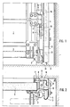
- Fig. 1 einen unteren Seitenbereich eines Torblattes mit Rollenführungsschiene und Fanggerät in Draufsicht auf den Torblattbereich;
- Fig.2 denselben Eckbereich, jedoch in Richtung des Drahtseiles gesehen;
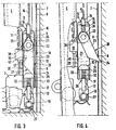
- Fig. 3 eine Ansicht auf die Schmalseite des Torblattes mit geschnittenem Fanggliedgehäuse und der Fangklinke in Freigabestellung;
- Fig. 4 eine der Fig. entsprechende Darstellung mit der Fangklinke in Fangstellung.
- 1 shows a lower side area of a door leaf with roller guide rail and safety gear in a top view of the door leaf area;
- 2 shows the same corner area, but seen in the direction of the wire rope;
- 3 shows a view of the narrow side of the door leaf with a cut catch housing and the catch pawl in the release position;
- Fig. 4 is an illustration corresponding to the catch with the catch in the catch position.
Wie insbesondere aus den Figuren 1 und 2 ersichtlich, sind an dem Torblatt über Rollenhalter 2 Rollen 3 befestigt, die in eine Führungsschiene 4 eingelagert sind. Von diesen Rollenhaltern und Rollen sind insbesondere bei einem sogenannten Sektionaltor eine ganze Reihe vorhanden, wie dies bekannt ist. Weiterhin hat man sich selbstverständlich die für den im Bild rechten Randbereich vorgesehenen Bauteile und Baumassnahmen spiegelsymmetrisch für den nicht dargestellten linken Randbereich des Torblattes vorzustellen. Die Führungsschienen 4 sind mittels Halterungen 5 im Bereich der seitlichen Gebäudeöffnungsberandung in nicht weiter dargestellter Weise festgelegt. An den Halterungen 5 sind zugleich Fangschienen 7 befestigt, die sich somit ebenfalls im Bereich der seitlichen Gebäudeöffnungsberandung 6 befinden und dort entsprechend gut abstützen können. Wie insbesondere Figur 1 erkennen lässt, sind die Fangschienen 7 mit einer Reihe in Längsrichtung aufeinanderfolgend angeordneter Fangöffnungen 8 versehen, die verhältnismässig breit ausgeführt sind, im vorliegenden Falle breiter als die ihnen zugewandte Seite eines Fanggliedgehäuses 10, das im Schmalseitenbereich des Torblattes angeordnet ist, wie dies v.a. Fig. 2 erkennen lässt. An der der Fangschiene 7 gegenüberliegenden Gehäuseseite greift ein Führungsbeschlag 11 an, so dass das - wie später noch geschildert - im Fangfall sich gegenüber dem Torblatt 1 entlang seiner Schmalseite verschiebende Fanggliedgehäuse 10 mit in der Fangstellung befindlichem Fangglied - Fig. 4 - nicht von der Fangschiene 7 fortgerichtet ausweichen kann.As can be seen in particular from FIGS. 1 and 2,
Fig. zeigt - wie auch die Figuren 3 und 4 - einen Bolzen 12, der bei 13 an einem Befestigungsbolzen 27 angreift, wobei 13 eine Öse innerhalb einer Lasche sein kann. Dieser Bolzen 12 greift durch die untere Stirnseite 17 des Gehäuses 10 in dessen Inneres ein. Durch die dieser Stirnseite gegenüberliegende obere Stirnseite 16 ist eine Klemmhülse 15 hindurchgeführt, mit welcher das als Zugmittelstrang dienende Drahtseil 14 zu einer Schlaufe geformt zusammengefasst ist.3 shows - like FIGS. 3 and 4 - a
Die Teilschnittdarstellungen nach den Fig. 3 und 4 zeigen die Ausbildung des Fanggliedgehäuses 10 und der diesem zugeordneten Bauteile deutlich. Das Gehäuse weist innerhalb seiner der Fangschiene 7 zugewandten Längsseitenwand 18 eine seitliche Öffnung 19 auf, die der Gehäuseseite 20 gegenüberliegt, an welcher der Führungsbeschlag 11 abstützend angreift. Die weiteren seitlichen Gehäusewandungen 21, die sich senkrecht zu den Wandungen 18 und 20 erstrecken und von denen man aufgrund des Gehäuseschnittes nur die hintere erkennt, halten zwischen sich eine Schwenkachse 22, um welche die Fangklinke 23 verschwenkbar gelagert ist. Wie Fig. 3 erkennen lässt, befindet sich die Schwenkklinke samt der Klinkennase innerhalb des Fanggliedgehäuses 10, wenn die Fangklinke 23 aufgrund eines ausreichenden Spannungszustandes in dem zugehörigen Seil 14 sich in der Freigabestellung befindet, die den normalen Betriebsfall bei intaktem Seil, ordnungsgemäss arbeitender Gewichtsausgleichseinrichtung und dgl. darstellt. Der mittels der Öse 13 und dem Befestigungsbolzen 27 im unteren Seitenbereich des Torblattes gehaltene Bolzen 12 durchgreift die untere Stirnseite 17 durch eine Durchführungsöffnung 28 verschiebbar. In seinem im Inneren des Gehäuses liegenden Endbereich ist der Bolzen 12 mit einem Kopf 29 versehen, der derart verbreitert ausgeführt ist, dass die Seitenflächen des Bolzenkopfes an den Gehäuseinnenseitenwandungen geführt wird. Zwischen der Innenwand der unteren Stirnseite 17 des Gehäuses 10 und der dieser gegenüberliegenden Unterfläche des Kopfes 29 ist eine Schraubendruckfeder 32 vorgesehen, durch welche der Bolzenschaft hindurchgeführt ist. Um die Schraubenfeder herum ist ein hülsenförmiger Anschlag 33 angeordnet, der wiederum einen Endes an der Innenfläche der Stirnseite 17 und anderen Endes an der dieser zugewandten Unterfläche des Kopfes 29 abgestützt ist. Wie in Fig. 3 gezeigt, befindet sich der Bolzen 12 bei gespanntem Seil 14 mit seinem Kopf 29 in Anlage mit dem Anschlag 33, so dass die Schraubendruckfeder 32 ihre grösstmögliche Zusammendrückunq aufweist.The partial sectional views according to FIGS. 3 and 4 clearly show the design of the catching
An dem Bolzenkopf 29 ist eine Abschrägung 30 ausgebildet, die hinsichtlich der Schräge mit dem Verlauf einer Schrägfläche 31 übereinstimmt, an der die Abschrägung 30 anliegt und die ausgehend von der Klinkennase 24 in dem der Schwenkachse 22 gegenüberliegenden Bereich der Fangklinke an dieser ausgebildet ist. Diese Anlage zeigt Fig. 3 für die Freigabestellung 25 der Fangklinke.On the
Wenn das Seil 14 reisst oder aus anderen Gründen seine Spannung verliert, so verschiebt sich das Gehäuse 10 gegenüber dem Bolzen 12 nach unten, und zwar unter der Kraft der zusammengedrückten und sich nunmehr entspannenden Feder 32 weitaus schneller als die Anfangsgeschwindigkeit des nunmehr absturzgefährdeten Torblattes. In Fig. 4 ist die Relativlage zwischen dem in durchgezogenen Strichen wiedergegebenen Gehäuse 10 und dem strichpunktiert wiedergegebenen Kopf 29 des Bolzens 12 dargestellt, der also bei sich entspannender Feder 32 in diese strichpunktierte Endverschiebelage 40 in das Gehäuseinnere hinein gelangt. Dabei drückt der Kopf 29 über seine Abschrägung 30 an der Schrägfläche 31 der Fangklinke 23 entlanggleitend die Fangklinke in Drehbewegung um die Schwenkachse 22 herum mit der Klinkennase 24 zuerst durch die seitliche Öffnung 19, so dass die Klinkennase 24 in die nach unten nächstfolgende Fangöffnung 8 der Fangschiene 7 eingreift, wie dies Fig. 4 zeigt. In dieser Lage befindet sich die Fangklinke 23 somit in der Fangstellung 26.If the
Die Klemmhülse 15 des Seiles 14 durchgreift eine Durchtrittsöffnung 34 in der oberen Stirnseite 16 des Gehäuses 10, und zwar ebenfalls längsverschiebbar. Die im Inneren des Gehäuses 10 liegende Seilschlaufe greift in eine Kausche 35 ein, die ihrerseits die Schwenkachse 22 umfasst, und zwar mit einem gewissen Spiel derart, dass bei Schlaffwerden des Seiles eine zwischen der Innenwand der Stirnseite 16 und der Kausche 35 angeordnete Druckfeder 32, die das Seil 14 und dessen durch die Hülse 15 zurückgeführtes Ende umgreift, die Kausche 35 gegenüber der Schwenkachse 22 in das Gehäuseinnere um eine geringe Strecke verschiebt. An der Kausche 35 greift ein Betätigungsglied 38 eines elektrischen Schalters 39 an, mit welchem ein hier vorgesehener Antriebsmotor abgeschaltet wird. Da die Schraubendruckfeder 32, die den Bolzen 12 umfasst, härter bzw. steifer ausgebildet ist als die Druckfeder 36, die das Seil 14 umgreift, verschiebt sich zunächst das Gehäuse 10 gegenüber dem Bolzen 12, so dass die Fangklinke 23 in ihre Fangstellung 26 gerät, woraufhin die Verschiebung der Kausche 35 zur Betätigung des Schalters 39 Platz greift.The clamping
Wie Fig. 3 zeigt, weist die Fangklinke 23 an ihrer der Fangschiene 7 abgewandten Seite eine Gewinde-Sacklochbohrung 41 auf, die in der Freigabestellung 25 der Klinke 23 hinsichtlich ihrer Eingangsöffnung mit einer Bohrung 42 in der Gehäuseseite 20 fluchtet. Durch eine von der Gehäuseaussenseite her durch die Bohrung 42 in das Gewindesackloch 41 eingeführte Schraube kann die Fangklinke 23 in der Freigabestellung gehalten bzw. in diese zurückgeführt und dort arretiert werden, wenn das Torblatt nach einem Fangfall nicht nur geöffnet werden soll - die Fangklinke würde wie eine Ratsche wirken -, sondern auch verschliessbar sein soll, beispielsweise mit Hilfe eines Gabelstaplers, bis das defekte Seil bzw. der zum Schlaffwerden des Seiles führende Fehler beseitigt worden ist.As shown in FIG. 3, the
Wie bereits eingangs kurz erwähnt, sind die Fangöffnungen 8 quer zur Bewegungsrichtung des Torblattes 1 sehr breit ausgebildet, und zwar um ein Vielfaches der Breite der Klinkennase 24, so dass das Tor in jeder möglichen seitlichen Versetzbewegung sicher gefangen werden kann. Ein einseitiger Fehler, beispielsweise Seilriss, führt zu keinem Verklemmen des Tores derart, dass dieses nicht angehoben werden kann.As already briefly mentioned at the beginning, the
Claims (22)
Priority Applications (1)
| Application Number | Priority Date | Filing Date | Title |
|---|---|---|---|
| AT85107467T ATE38265T1 (en) | 1984-07-23 | 1985-06-14 | FISHING GEAR. |
Applications Claiming Priority (2)
| Application Number | Priority Date | Filing Date | Title |
|---|---|---|---|
| DE3427105 | 1984-07-23 | ||
| DE19843427105 DE3427105A1 (en) | 1984-07-23 | 1984-07-23 | Fishing gear |
Publications (2)
| Publication Number | Publication Date |
|---|---|
| EP0172351A1 EP0172351A1 (en) | 1986-02-26 |
| EP0172351B1 true EP0172351B1 (en) | 1988-10-26 |
Family
ID=6241335
Family Applications (1)
| Application Number | Title | Priority Date | Filing Date |
|---|---|---|---|
| EP85107467A Expired EP0172351B1 (en) | 1984-07-23 | 1985-06-14 | Safety catch |
Country Status (6)
| Country | Link |
|---|---|
| EP (1) | EP0172351B1 (en) |
| AT (1) | ATE38265T1 (en) |
| DE (2) | DE3427105A1 (en) |
| DK (1) | DK162787C (en) |
| ES (1) | ES8609569A1 (en) |
| NO (1) | NO161935C (en) |
Cited By (5)
| Publication number | Priority date | Publication date | Assignee | Title |
|---|---|---|---|---|
| DE4413465A1 (en) * | 1994-04-18 | 1995-10-19 | Hoermann Kg | Vertically opening door with holding ratchet |
| EP1229197A2 (en) | 2001-02-05 | 2002-08-07 | Hörmann Kg Amshausen | Single panelled overhead door |
| EP1882801A1 (en) | 2001-02-05 | 2008-01-30 | Hörmann Kg Amshausen | Single-leaf head-over gate and suspension system therefor |
| DE10115571B4 (en) * | 2001-02-05 | 2013-11-07 | Hörmann KG Amshausen | One-leaf overhead tilt gate with fall protection |
| DE10153366B4 (en) * | 2001-02-05 | 2016-01-07 | Hörmann KG Amshausen | One-leaf overhead gate with safety fall arrest |
Families Citing this family (12)
| Publication number | Priority date | Publication date | Assignee | Title |
|---|---|---|---|---|
| DE3730363C1 (en) * | 1987-09-10 | 1988-12-08 | Gfa Antriebstechnik Gmbh | Catch device |
| DE3800789C2 (en) * | 1988-01-14 | 1994-10-20 | Einwich Georg | Safety gear for manually and power operated gates, especially for sectional gates |
| DE3912291C1 (en) * | 1989-04-14 | 1990-07-26 | Reinhard 3005 Hemmingen De Zills | |
| ES2046060B1 (en) * | 1991-05-06 | 1997-01-01 | Roper S A | SAFETY MECHANISM FOR DOORS BALANCED BY COUNTERWEIGHT WITH SUSPENSION CABLE. |
| ES2134972T3 (en) * | 1994-04-18 | 1999-10-16 | Hoermann Kg | DOOR WITH A SCROLLABLE DOOR LEAF AND RETENTION RATCHET DEVICE. |
| FR2746842B1 (en) * | 1996-03-27 | 2000-12-15 | Cardo Door France | VERTICAL MOTION DOOR |
| DE10113847A1 (en) * | 2001-03-21 | 2002-09-26 | Hoermann Kg | Securing device for a door leaf of a tilting or sectional door moving along a path between an open position and a closed position comprises a securing element interacting with other securing elements to secure the door leaf |
| DE20108860U1 (en) * | 2001-05-25 | 2001-08-23 | Achenbach Karl Gmbh & Co Kg | Security blocking means for a ceiling door |
| CA2419185A1 (en) | 2003-02-19 | 2004-08-19 | Pierre-Louis Foucault | Cable failure device for garage doors and the like |
| ES2311313B1 (en) * | 2005-05-13 | 2009-08-19 | Puertas Cubells, S.L. | ANTICENT DEVICE FOR DOORS OF VERTICAL OPERATION GUILLOTINE TYPE OF ONE OR VARIOUS LEAVES. |
| EP2016247A4 (en) | 2006-05-08 | 2013-07-17 | Canimex Inc | Brake device with integrated anti-theft mechanism for garage doors and the like, and door assembly including the same |
| PL2459827T3 (en) * | 2009-07-31 | 2018-12-31 | Hörmann KG Antriebstechnik | Door drive device having traction means monitoring and door provided therewith |
Family Cites Families (6)
| Publication number | Priority date | Publication date | Assignee | Title |
|---|---|---|---|---|
| DE620566C (en) * | 1934-07-26 | 1935-10-23 | Francois Giessner | Safety device for sliding window |
| FR1148630A (en) * | 1955-03-10 | 1957-12-12 | Hartmann & Co A G | Device used to intercept during its fall an object suspended from a traction member when this member ceases to act as such, for example due to breakage |
| DE1727130U (en) * | 1956-04-30 | 1956-07-26 | Hugo Stinn | SLIDING WINDOW SECURITY DEVICE. |
| FR1173336A (en) * | 1957-03-26 | 1959-02-24 | Safety device for overhead doors | |
| CH483547A (en) * | 1967-11-20 | 1969-12-31 | Verwo Ag | Safety catch for up-and-over gates suspended from ropes |
| NL8202877A (en) * | 1982-07-15 | 1984-02-01 | Cornelis Willem Nissen | Heavy roller shutter door - has rod linkage safety mechanism utilising gravity force towards closing position |
-
1984
- 1984-07-23 DE DE19843427105 patent/DE3427105A1/en active Granted
-
1985
- 1985-06-14 AT AT85107467T patent/ATE38265T1/en not_active IP Right Cessation
- 1985-06-14 DE DE8585107467T patent/DE3565874D1/en not_active Expired
- 1985-06-14 EP EP85107467A patent/EP0172351B1/en not_active Expired
- 1985-07-22 NO NO852908A patent/NO161935C/en not_active IP Right Cessation
- 1985-07-22 DK DK331985A patent/DK162787C/en not_active IP Right Cessation
- 1985-07-22 ES ES545444A patent/ES8609569A1/en not_active Expired
Cited By (6)
| Publication number | Priority date | Publication date | Assignee | Title |
|---|---|---|---|---|
| DE4413465A1 (en) * | 1994-04-18 | 1995-10-19 | Hoermann Kg | Vertically opening door with holding ratchet |
| DE4413465C2 (en) * | 1994-04-18 | 2001-05-31 | Hoermann Kg | Gate with a vertically movable door leaf and a catch mechanism |
| EP1229197A2 (en) | 2001-02-05 | 2002-08-07 | Hörmann Kg Amshausen | Single panelled overhead door |
| EP1882801A1 (en) | 2001-02-05 | 2008-01-30 | Hörmann Kg Amshausen | Single-leaf head-over gate and suspension system therefor |
| DE10115571B4 (en) * | 2001-02-05 | 2013-11-07 | Hörmann KG Amshausen | One-leaf overhead tilt gate with fall protection |
| DE10153366B4 (en) * | 2001-02-05 | 2016-01-07 | Hörmann KG Amshausen | One-leaf overhead gate with safety fall arrest |
Also Published As
| Publication number | Publication date |
|---|---|
| DK162787C (en) | 1992-04-27 |
| DE3427105C2 (en) | 1988-08-04 |
| NO161935B (en) | 1989-07-03 |
| NO852908L (en) | 1986-01-24 |
| EP0172351A1 (en) | 1986-02-26 |
| ATE38265T1 (en) | 1988-11-15 |
| DE3565874D1 (en) | 1988-12-01 |
| ES8609569A1 (en) | 1986-08-01 |
| DK331985D0 (en) | 1985-07-22 |
| DE3427105A1 (en) | 1986-01-30 |
| DK162787B (en) | 1991-12-09 |
| DK331985A (en) | 1986-01-24 |
| NO161935C (en) | 1989-10-11 |
| ES545444A0 (en) | 1986-08-01 |
Similar Documents
| Publication | Publication Date | Title |
|---|---|---|
| EP0172351B1 (en) | Safety catch | |
| EP0956417B1 (en) | Cable-controlled window winder with a guiding track | |
| EP0151427B1 (en) | Spring monitoring device | |
| DE69633978T2 (en) | DEVICE FOR OPENING AND CLOSING AUTOMATIC DOORS OF AN ELEVATOR | |
| DE4105872C2 (en) | ||
| EP0634353A2 (en) | Door closing system | |
| DE4024666C2 (en) | Sectional gate | |
| DE19836705C2 (en) | Window lifter with anti-trap protection | |
| DE202017103555U1 (en) | Auxiliary drive for a safety brake device | |
| EP2459827A1 (en) | Door drive device having traction means monitoring and door provided therewith | |
| DE3710237A1 (en) | Catching device for doors opening upwards | |
| DE2618110A1 (en) | Drive for up and over door - has driven chain within slotted profile and carriers and switch actuators | |
| DE3913214C2 (en) | Slack rope belay device | |
| DE102009039623B4 (en) | Door drive device with Zugmittelüberwachungseinrichtung and thus provided gate | |
| EP0279929A2 (en) | Fall protection device | |
| DE19533153A1 (en) | Sliding door for emergency exit | |
| DE3413236A1 (en) | Catch device for a door leaf moveable approximately vertically into the closed position | |
| DE3600316C2 (en) | Safety device for rope lifting devices | |
| EP0698174B1 (en) | Fall-prevention device | |
| EP0675261B1 (en) | Roller door with flexible door leaf | |
| EP0781892B1 (en) | Automatic sliding door with at least one wing | |
| DE8421918U1 (en) | Fishing gear | |
| DE2917023B2 (en) | Cable hoist with gate hanger and built-in slack rope safety device for a ceiling link or roller door | |
| EP1225292A2 (en) | Door | |
| DE4100608A1 (en) | Automatic safety switch mechanism - is for electrically driven roller blinks and cuts off power when cord is over-tensioned |
Legal Events
| Date | Code | Title | Description |
|---|---|---|---|
| PUAI | Public reference made under article 153(3) epc to a published international application that has entered the european phase |
Free format text: ORIGINAL CODE: 0009012 |
|
| AK | Designated contracting states |
Designated state(s): AT BE CH DE FR GB IT LI LU NL SE |
|
| 17P | Request for examination filed |
Effective date: 19860820 |
|
| 17Q | First examination report despatched |
Effective date: 19880114 |
|
| GRAA | (expected) grant |
Free format text: ORIGINAL CODE: 0009210 |
|
| AK | Designated contracting states |
Kind code of ref document: B1 Designated state(s): AT BE CH DE FR GB IT LI LU NL SE |
|
| REF | Corresponds to: |
Ref document number: 38265 Country of ref document: AT Date of ref document: 19881115 Kind code of ref document: T |
|
| REF | Corresponds to: |
Ref document number: 3565874 Country of ref document: DE Date of ref document: 19881201 |
|
| ET | Fr: translation filed | ||
| ITF | It: translation for a ep patent filed |
Owner name: SOCIETA' ITALIANA BREVETTI S.P.A. |
|
| GBT | Gb: translation of ep patent filed (gb section 77(6)(a)/1977) | ||
| PLBE | No opposition filed within time limit |
Free format text: ORIGINAL CODE: 0009261 |
|
| STAA | Information on the status of an ep patent application or granted ep patent |
Free format text: STATUS: NO OPPOSITION FILED WITHIN TIME LIMIT |
|
| 26N | No opposition filed | ||
| ITTA | It: last paid annual fee | ||
| EPTA | Lu: last paid annual fee | ||
| EAL | Se: european patent in force in sweden |
Ref document number: 85107467.4 |
|
| REG | Reference to a national code |
Ref country code: GB Ref legal event code: IF02 |
|
| PGFP | Annual fee paid to national office [announced via postgrant information from national office to epo] |
Ref country code: LU Payment date: 20020606 Year of fee payment: 18 |
|
| PG25 | Lapsed in a contracting state [announced via postgrant information from national office to epo] |
Ref country code: LU Free format text: LAPSE BECAUSE OF NON-PAYMENT OF DUE FEES Effective date: 20030614 |
|
| PGFP | Annual fee paid to national office [announced via postgrant information from national office to epo] |
Ref country code: GB Payment date: 20040609 Year of fee payment: 20 |
|
| PGFP | Annual fee paid to national office [announced via postgrant information from national office to epo] |
Ref country code: SE Payment date: 20040611 Year of fee payment: 20 |
|
| PGFP | Annual fee paid to national office [announced via postgrant information from national office to epo] |
Ref country code: AT Payment date: 20040618 Year of fee payment: 20 |
|
| PGFP | Annual fee paid to national office [announced via postgrant information from national office to epo] |
Ref country code: CH Payment date: 20040628 Year of fee payment: 20 |
|
| PGFP | Annual fee paid to national office [announced via postgrant information from national office to epo] |
Ref country code: NL Payment date: 20040629 Year of fee payment: 20 Ref country code: FR Payment date: 20040629 Year of fee payment: 20 |
|
| PGFP | Annual fee paid to national office [announced via postgrant information from national office to epo] |
Ref country code: DE Payment date: 20040701 Year of fee payment: 20 |
|
| PGFP | Annual fee paid to national office [announced via postgrant information from national office to epo] |
Ref country code: BE Payment date: 20040728 Year of fee payment: 20 |
|
| PG25 | Lapsed in a contracting state [announced via postgrant information from national office to epo] |
Ref country code: GB Free format text: LAPSE BECAUSE OF EXPIRATION OF PROTECTION Effective date: 20050613 |
|
| PG25 | Lapsed in a contracting state [announced via postgrant information from national office to epo] |
Ref country code: NL Free format text: LAPSE BECAUSE OF EXPIRATION OF PROTECTION Effective date: 20050614 |
|
| BE20 | Be: patent expired |
Owner name: *HORMANN K.G. BROCKHAGEN Effective date: 20050614 |
|
| REG | Reference to a national code |
Ref country code: GB Ref legal event code: PE20 |
|
| REG | Reference to a national code |
Ref country code: CH Ref legal event code: PL |
|
| NLV7 | Nl: ceased due to reaching the maximum lifetime of a patent |
Effective date: 20050614 |
|
| EUG | Se: european patent has lapsed | ||
| BE20 | Be: patent expired |
Owner name: *HORMANN K.G. BROCKHAGEN Effective date: 20050614 |