EP0172351B1 - Dispositif antichute - Google Patents
Dispositif antichute Download PDFInfo
- Publication number
- EP0172351B1 EP0172351B1 EP85107467A EP85107467A EP0172351B1 EP 0172351 B1 EP0172351 B1 EP 0172351B1 EP 85107467 A EP85107467 A EP 85107467A EP 85107467 A EP85107467 A EP 85107467A EP 0172351 B1 EP0172351 B1 EP 0172351B1
- Authority
- EP
- European Patent Office
- Prior art keywords
- catching
- catching member
- housing
- member housing
- door
- Prior art date
- Legal status (The legal status is an assumption and is not a legal conclusion. Google has not performed a legal analysis and makes no representation as to the accuracy of the status listed.)
- Expired
Links
Images
Classifications
-
- E—FIXED CONSTRUCTIONS
- E05—LOCKS; KEYS; WINDOW OR DOOR FITTINGS; SAFES
- E05D—HINGES OR SUSPENSION DEVICES FOR DOORS, WINDOWS OR WINGS
- E05D13/00—Accessories for sliding or lifting wings, e.g. pulleys, safety catches
- E05D13/003—Anti-dropping devices
- E05D13/006—Anti-dropping devices fixed to the wing, i.e. safety catches
-
- E—FIXED CONSTRUCTIONS
- E05—LOCKS; KEYS; WINDOW OR DOOR FITTINGS; SAFES
- E05F—DEVICES FOR MOVING WINGS INTO OPEN OR CLOSED POSITION; CHECKS FOR WINGS; WING FITTINGS NOT OTHERWISE PROVIDED FOR, CONCERNED WITH THE FUNCTIONING OF THE WING
- E05F15/00—Power-operated mechanisms for wings
-
- E—FIXED CONSTRUCTIONS
- E05—LOCKS; KEYS; WINDOW OR DOOR FITTINGS; SAFES
- E05F—DEVICES FOR MOVING WINGS INTO OPEN OR CLOSED POSITION; CHECKS FOR WINGS; WING FITTINGS NOT OTHERWISE PROVIDED FOR, CONCERNED WITH THE FUNCTIONING OF THE WING
- E05F15/00—Power-operated mechanisms for wings
- E05F15/40—Safety devices, e.g. detection of obstructions or end positions
- E05F15/41—Detection by monitoring transmitted force or torque; Safety couplings with activation dependent upon torque or force, e.g. slip couplings
-
- E—FIXED CONSTRUCTIONS
- E05—LOCKS; KEYS; WINDOW OR DOOR FITTINGS; SAFES
- E05Y—INDEXING SCHEME RELATING TO HINGES OR OTHER SUSPENSION DEVICES FOR DOORS, WINDOWS OR WINGS AND DEVICES FOR MOVING WINGS INTO OPEN OR CLOSED POSITION, CHECKS FOR WINGS AND WING FITTINGS NOT OTHERWISE PROVIDED FOR, CONCERNED WITH THE FUNCTIONING OF THE WING
- E05Y2400/00—Electronic control; Power supply; Power or signal transmission; User interfaces
- E05Y2400/80—User interfaces
- E05Y2400/85—User input means
- E05Y2400/852—Sensors
- E05Y2400/856—Actuation thereof
- E05Y2400/858—Actuation thereof by body parts
- E05Y2400/86—Actuation thereof by body parts by hand
-
- E—FIXED CONSTRUCTIONS
- E05—LOCKS; KEYS; WINDOW OR DOOR FITTINGS; SAFES
- E05Y—INDEXING SCHEME RELATING TO HINGES OR OTHER SUSPENSION DEVICES FOR DOORS, WINDOWS OR WINGS AND DEVICES FOR MOVING WINGS INTO OPEN OR CLOSED POSITION, CHECKS FOR WINGS AND WING FITTINGS NOT OTHERWISE PROVIDED FOR, CONCERNED WITH THE FUNCTIONING OF THE WING
- E05Y2900/00—Application of doors, windows, wings or fittings thereof
- E05Y2900/10—Application of doors, windows, wings or fittings thereof for buildings or parts thereof
- E05Y2900/106—Application of doors, windows, wings or fittings thereof for buildings or parts thereof for garages
Definitions
- the invention relates to a fishing gear with the features of the preamble of claim 1.
- Such gear devices which often work with catch pawls, are known in a wide variety of designs, for example from DE-A 2 735123.
- the invention has for its object to provide a fishing gear of the type mentioned that works quickly and safely, is protected against dirt and damage and in particular can also be easily maintained and checked for functionality.
- the catching device By arranging practically all parts to be moved in the course of a catching process inside a housing, the catching device is initially protected against dirt and damage, the arrangement being such that when the associated traction cable strand slackens or tears, the catching member gets into the catching position before due to its inertia, the closing leaf or door leaf moves significantly downwards.
- the spring used in this context is also located inside the housing, so it is primarily protected against the fact that its effective spring length is restricted by foreign bodies that are unwantedly stored in the spring travel.
- the catching element can be transferred from the release position to the catching position along a translational path by the spring-loaded bolt in the case of slackening of the rope.
- the catch element is designed as a catch pawl which is pivotably mounted within the housing and engages with an inclined surface seen in the longitudinal direction of the bolt on the bolt end lying inside the housing, so that the bolt pivots the pawl into the catch position outside the housing due to its spring load, as soon as the spring can work due to a broken rope or the like.
- the spring arranged between the closing leaf and the traction element strand has the advantage that accelerations of the closing leaf applied in manual operation, in particular, are transmitted in a dampened manner to the weight compensation device, so that the traction element strands, which are designed in particular as ropes, cannot jump off the cable drums. So far, a separate spring arm has been provided for this. Because the safety device designed according to the invention also fulfills this function, one can do without the spring lever which is otherwise to be provided in the same place.
- the catching device is particularly preferably designed such that the direction of movement of the catching element runs approximately perpendicular to the plane of the closing leaf, so that the catching element engages in the catching position on a catching rail which can advantageously be arranged close to the surf of the gate opening to be closed.
- a catching rail which can advantageously be arranged close to the surf of the gate opening to be closed.
- the catching member housing which moves in relation to the closing leaf when caught, is supported at least on its side facing away from the catching rail.
- the catching device basically works over the entire path that the closing sheet travels between its open position and its inclined position.
- the door leaf makes lateral movements within a certain scope. With appropriately wide catch openings, you can ensure that no jamming occurs in all these cases. You often have the need to open or close a trapped door leaf. This is done simply by reaching under and lifting the door leaf with a forklift or the like.
- the catch member can be locked in the release position for lowering, for example fixed in this position by a screw. In this way, the door leaf can be opened and closed. In the normal case, the catch member can pass through this locking opening with the help of a pin or the like can be operated particularly easily to check the functionality.
- the gear can be easily attached to building locks of the type in question.
- existing, cable-borne door leaves one simply loosens the cable attachment to the laterally protruding fastening bolts and hangs the bolts of the safety gear housing on them, while the cable end is laid in the safety gear housing and fastened there, which is preferably done on the pivot axis of the safety catch.
- the displacement of the catching element into the catching position can be used to actuate a feed current switch.
- a second movement under the force of a second spring is provided for this purpose, which works following the spring that triggers the catching element.
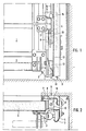
- rollers 3 which are embedded in a guide rail 4 are fastened to the door leaf via roller holders.
- a large number of these roller holders and rollers are available, in particular in a so-called sectional door, as is known.
- the guide rails 4 are fixed by means of brackets 5 in the area of the side edge of the building opening in a manner not shown.
- catch rails 7 are also attached, which are thus also in the area of the side building opening 6 and can support them there accordingly.
- the catch rails 7 are provided with a series of catch openings 8 which are arranged in the longitudinal direction and are relatively wide, in the present case wider than the side of a catch member housing 10 facing them, which is arranged in the narrow side area of the door leaf, such as this especially Fig. 2 reveals.
- a guide fitting 11 engages on the housing side opposite the catch rail 7, so that the catch member housing 10 with catch member in the catch position - FIG. 4 - which moves in the catch position - FIG. 4 - does not detach from the catch rail, as described later - in the event of a catch relative to the door leaf 1 along its narrow side 7 can avoid evasive.
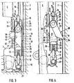
- FIGS. 3 and 4 show - like FIGS. 3 and 4 - a bolt 12 which engages at 13 on a fastening bolt 27, 13 being an eyelet within a tab.
- This bolt 12 engages through the lower end face 17 of the housing 10 in its interior.
- a clamping sleeve 15 is passed through the upper end face 16 opposite this end face, with which the wire rope 14 serving as a traction means strand is combined to form a loop.
- FIGS. 3 and 4 clearly show the design of the catching member housing 10 and the components assigned to it.
- the housing Within its longitudinal side wall 18 facing the catch rail 7, the housing has a lateral opening 19 which lies opposite the housing side 20, on which the guide fitting 11 engages in a supporting manner.
- the swivel pawl including the pawl nose, is located within the catch member housing 10 when the catch pawl 23 is in the release position due to a sufficient tension condition in the associated rope 14, which is the normal operating situation with the rope intact, properly functioning weight balancing device and The like.
- the bolt 12 In its end region located inside the housing, the bolt 12 is provided with a head 29 which is widened in such a way that the side surfaces of the bolt head are guided on the inner walls of the housing.
- a helical compression spring 32 is provided between the inner wall of the lower end face 17 of the housing 10 and the lower surface of the head 29 opposite this, through which the bolt shaft is passed.
- a sleeve-shaped stop 33 is arranged around the helical spring, which in turn is supported at one end on the inner surface of the end face 17 and at the other end on the lower surface of the head 29 facing it. As shown in Fig. 3, the bolt 12 is in tension with the rope 14 with its head 29 in contact with the stop 33, so that the helical compression spring 32 has its greatest possible compression.
- a bevel 30 is formed which, with respect to the bevel, corresponds to the course of an inclined surface 31 against which the bevel 30 rests and which, starting from the pawl nose 24, is formed on the catch pawl in the region of the catch pawl opposite the pivot axis 22.
- This system is shown in FIG. 3 for the release position 25 of the catch.
- the head 29 presses, via its bevel 30, along the inclined surface 31 of the catch pawl 23, sliding the catch pawl in rotary motion around the pivot axis 22 with the pawl nose 24 first through the lateral opening 19, so that the pawl nose 24 into the catch opening 8 which follows next to the bottom Catch rail 7 engages, as shown in Fig. 4.
- the catch pawl 23 is thus in the catch position 26.
- the clamping sleeve 15 of the cable 14 passes through a passage opening 34 in the upper end face 16 of the housing 10, and also in a longitudinally displaceable manner.
- the rope loop located in the interior of the housing 10 engages in a thimble 35, which in turn encompasses the pivot axis 22, with a certain amount of play such that when the rope becomes slack, a compression spring 32 arranged between the inner wall of the end face 16 and the thimble 35 which engages around the cable 14 and its end returned through the sleeve 15, displaces the thimble 35 by a small distance relative to the pivot axis 22 into the interior of the housing.
- an actuator 38 of an electrical switch 39 engages with which a drive motor provided here is switched off. Since the helical compression spring 32, which comprises the bolt 12, is designed to be harder or stiffer than the compression spring 36, which encompasses the cable 14, the housing 10 first moves relative to the bolt 12, so that the catch pawl 23 moves into its catch position 26, whereupon the displacement of the thimble 35 for actuating the switch 39 takes place.
- the catch pawl 23 has on its side facing away from the catch rail 7 a threaded blind hole 41 which, in the release position 25 of the pawl 23, is aligned with a bore 42 in the housing side 20 with respect to its input opening.
- the catch pawl 23 can be held in the release position or returned to it and locked there if the door leaf is not only to be opened after a fall, the catch pawl would be like a ratchet - but should also be lockable, for example with the help of a forklift, until the defective rope or the fault causing the rope to become slack has been eliminated.
- the catch openings 8 are very wide transversely to the direction of movement of the door leaf 1, namely by a multiple of the width of the latch nose 24, so that the door can be caught safely in any possible lateral displacement movement.
- a one-sided error such as a rope break, does not cause the door to jam in such a way that it cannot be lifted.
Claims (22)
Priority Applications (1)
| Application Number | Priority Date | Filing Date | Title |
|---|---|---|---|
| AT85107467T ATE38265T1 (de) | 1984-07-23 | 1985-06-14 | Fanggeraet. |
Applications Claiming Priority (2)
| Application Number | Priority Date | Filing Date | Title |
|---|---|---|---|
| DE19843427105 DE3427105A1 (de) | 1984-07-23 | 1984-07-23 | Fanggeraet |
| DE3427105 | 1984-07-23 |
Publications (2)
| Publication Number | Publication Date |
|---|---|
| EP0172351A1 EP0172351A1 (fr) | 1986-02-26 |
| EP0172351B1 true EP0172351B1 (fr) | 1988-10-26 |
Family
ID=6241335
Family Applications (1)
| Application Number | Title | Priority Date | Filing Date |
|---|---|---|---|
| EP85107467A Expired EP0172351B1 (fr) | 1984-07-23 | 1985-06-14 | Dispositif antichute |
Country Status (6)
| Country | Link |
|---|---|
| EP (1) | EP0172351B1 (fr) |
| AT (1) | ATE38265T1 (fr) |
| DE (2) | DE3427105A1 (fr) |
| DK (1) | DK162787C (fr) |
| ES (1) | ES8609569A1 (fr) |
| NO (1) | NO161935C (fr) |
Cited By (5)
| Publication number | Priority date | Publication date | Assignee | Title |
|---|---|---|---|---|
| DE4413465A1 (de) * | 1994-04-18 | 1995-10-19 | Hoermann Kg | Tor mit einem vertikal bewegbaren Torblatt und einer Fangklinkeneinrichtung |
| EP1229197A2 (fr) | 2001-02-05 | 2002-08-07 | Hörmann Kg Amshausen | Porte basculante à panneau unique |
| EP1882801A1 (fr) | 2001-02-05 | 2008-01-30 | Hörmann Kg Amshausen | Porte basculante à panneau unique et système de ressort associé |
| DE10115571B4 (de) * | 2001-02-05 | 2013-11-07 | Hörmann KG Amshausen | Ein-Blatt-Überkopf-Kipptor mit Absturzsicherung |
| DE10153366B4 (de) * | 2001-02-05 | 2016-01-07 | Hörmann KG Amshausen | Ein-Blatt-Überkopf-Tor mit Sicherheitsabsturzsicherung |
Families Citing this family (12)
| Publication number | Priority date | Publication date | Assignee | Title |
|---|---|---|---|---|
| DE3730363C1 (en) * | 1987-09-10 | 1988-12-08 | Gfa Antriebstechnik Gmbh | Catch device |
| DE3800789C2 (de) * | 1988-01-14 | 1994-10-20 | Einwich Georg | Fangvorrichtung für hand- und kraftbetätigte Tore, insbesondere für Sectional-Tore |
| DE3912291C1 (fr) * | 1989-04-14 | 1990-07-26 | Reinhard 3005 Hemmingen De Zills | |
| ES2046060B1 (es) * | 1991-05-06 | 1997-01-01 | Roper S A | Mecanismo de seguridad para puertas equilibradas por contrapesos con cable de suspension. |
| ATE183806T1 (de) * | 1994-04-18 | 1999-09-15 | Hoermann Kg | Tor mit einem bewegbaren torblatt und einer fangklinkeneinrichtung |
| FR2746842B1 (fr) * | 1996-03-27 | 2000-12-15 | Cardo Door France | Porte a mouvement vertical |
| DE10113847A1 (de) | 2001-03-21 | 2002-09-26 | Hoermann Kg | Sicherungsvorrichtung |
| DE20108860U1 (de) * | 2001-05-25 | 2001-08-23 | Achenbach Karl Gmbh & Co Kg | Sicherungsblockademittel für ein Deckenlauftor |
| CA2419185A1 (fr) | 2003-02-19 | 2004-08-19 | Pierre-Louis Foucault | Dispositif de securite en cas de rupture de cable de porte de garage et d'element semblable |
| ES2311313B1 (es) * | 2005-05-13 | 2009-08-19 | Puertas Cubells, S.L. | Dispositivo anticaida para puertas de funcionamiento vertical tipo guillotina de una o varias hojas. |
| WO2007128120A1 (fr) | 2006-05-08 | 2007-11-15 | Canimex Inc. | Dispositif de freinage avec mécanisme antivol intégré pour portes de garage et similaires et ensemble de porte incluant le dispositif |
| US20120186158A1 (en) * | 2009-07-31 | 2012-07-26 | Hormann Kg Antriebstechnik | Door drive device having traction means monitoring and door provided therewith |
Family Cites Families (6)
| Publication number | Priority date | Publication date | Assignee | Title |
|---|---|---|---|---|
| DE620566C (de) * | 1934-07-26 | 1935-10-23 | Francois Giessner | Sicherungsvorrichtung fuer Schiebefenster |
| FR1148630A (fr) * | 1955-03-10 | 1957-12-12 | Hartmann & Co A G | Dispositif servant à intercepter lors de sa chute un objet suspendu à un organe de traction lorsque cet organe cesse d'agir comme tel, par exemple pour cause de rupture |
| DE1727130U (de) * | 1956-04-30 | 1956-07-26 | Hugo Stinn | Schiebefenster-seilsicherungseinrichtung. |
| FR1173336A (fr) * | 1957-03-26 | 1959-02-24 | Dispositif de sécurité pour portes basculantes | |
| CH483547A (de) * | 1967-11-20 | 1969-12-31 | Verwo Ag | Fangvorrichtung für an Seilen aufgehängte Kipptore |
| NL8202877A (nl) * | 1982-07-15 | 1984-02-01 | Cornelis Willem Nissen | Beveiligingsmechanisme voor een met medewerking van de zwaartekracht naar de sluitstand bewegende deur. |
-
1984
- 1984-07-23 DE DE19843427105 patent/DE3427105A1/de active Granted
-
1985
- 1985-06-14 EP EP85107467A patent/EP0172351B1/fr not_active Expired
- 1985-06-14 AT AT85107467T patent/ATE38265T1/de not_active IP Right Cessation
- 1985-06-14 DE DE8585107467T patent/DE3565874D1/de not_active Expired
- 1985-07-22 ES ES545444A patent/ES8609569A1/es not_active Expired
- 1985-07-22 DK DK331985A patent/DK162787C/da not_active IP Right Cessation
- 1985-07-22 NO NO852908A patent/NO161935C/no not_active IP Right Cessation
Cited By (6)
| Publication number | Priority date | Publication date | Assignee | Title |
|---|---|---|---|---|
| DE4413465A1 (de) * | 1994-04-18 | 1995-10-19 | Hoermann Kg | Tor mit einem vertikal bewegbaren Torblatt und einer Fangklinkeneinrichtung |
| DE4413465C2 (de) * | 1994-04-18 | 2001-05-31 | Hoermann Kg | Tor mit einem vertikal bewegbaren Torblatt und einer Fangklinkeneinrichtung |
| EP1229197A2 (fr) | 2001-02-05 | 2002-08-07 | Hörmann Kg Amshausen | Porte basculante à panneau unique |
| EP1882801A1 (fr) | 2001-02-05 | 2008-01-30 | Hörmann Kg Amshausen | Porte basculante à panneau unique et système de ressort associé |
| DE10115571B4 (de) * | 2001-02-05 | 2013-11-07 | Hörmann KG Amshausen | Ein-Blatt-Überkopf-Kipptor mit Absturzsicherung |
| DE10153366B4 (de) * | 2001-02-05 | 2016-01-07 | Hörmann KG Amshausen | Ein-Blatt-Überkopf-Tor mit Sicherheitsabsturzsicherung |
Also Published As
| Publication number | Publication date |
|---|---|
| DK162787B (da) | 1991-12-09 |
| DE3427105A1 (de) | 1986-01-30 |
| DK162787C (da) | 1992-04-27 |
| DE3565874D1 (en) | 1988-12-01 |
| DK331985A (da) | 1986-01-24 |
| NO852908L (no) | 1986-01-24 |
| NO161935C (no) | 1989-10-11 |
| DE3427105C2 (fr) | 1988-08-04 |
| ES8609569A1 (es) | 1986-08-01 |
| ES545444A0 (es) | 1986-08-01 |
| DK331985D0 (da) | 1985-07-22 |
| ATE38265T1 (de) | 1988-11-15 |
| EP0172351A1 (fr) | 1986-02-26 |
| NO161935B (no) | 1989-07-03 |
Similar Documents
| Publication | Publication Date | Title |
|---|---|---|
| EP0172351B1 (fr) | Dispositif antichute | |
| EP0956417B1 (fr) | Leve-vitre a cable pourvu d'un rail | |
| EP0151427B1 (fr) | Appareil de contrôle pour ressort d'équilibrage | |
| DE69633978T2 (de) | Vorrichtung zur öffnung und schliessung von automatischen türen eines aufzugs | |
| DE4105872C2 (fr) | ||
| EP0634353A2 (fr) | Système de fermeture pour porte | |
| DE4024666C2 (de) | Sektionaltor | |
| DE19836705C2 (de) | Fensterheber mit Einklemmschutz | |
| DE202017103555U1 (de) | Hilfsantrieb für eine Bremsfangvorrichtung | |
| WO2011012571A1 (fr) | Dispositif d'entraînement de portail, avec dispositif de surveillance des moyens de traction, ainsi que portail qui en est équipé | |
| DE3710237A1 (de) | Fangvorrichtung fuer nach oben oeffnende tore | |
| DE2618110A1 (de) | Antriebsvorrichtung fuer einen kippbaren torfluegel | |
| DE3913214C2 (de) | Schlaffseil-Sicherungsgerät | |
| DE102009039623B4 (de) | Torantriebsvorrichtung mit Zugmittelüberwachungseinrichtung sowie damit versehenes Tor | |
| DE19533153A1 (de) | Schiebetür mit Notöffnungs- oder Notschließeinrichtung | |
| DE3413236A1 (de) | Fanggeraet fuer ein etwa vertikal in die schliessstellung bewegbares torblatt | |
| DE3600316C2 (de) | Sicherheitsvorrichtung für Seilhebevorrichtungen | |
| EP0698174B1 (fr) | Securite anti-chute pour portes ou volets roulants | |
| EP0675261B1 (fr) | Porte enroulable avec un vantail de porte souple | |
| EP0781892B1 (fr) | Porte coulissante automatique avec au moins un vantail | |
| DE8421918U1 (de) | Fanggerät | |
| DE2917023B2 (de) | Seilzug mit Toraufhänger und darin eingebauter Schlaffseilsicherung für ein Deckenglieder- oder Rolltor | |
| EP1225292A2 (fr) | Porte | |
| DE4100608A1 (de) | Antriebsvorrichtung fuer eine rollflaeche | |
| DE7912249U1 (de) | Seilzug mit toraufhaenger und darin eingebauter schlaffseilsicherung fuer ein deckenglieder- oder rolltor |
Legal Events
| Date | Code | Title | Description |
|---|---|---|---|
| PUAI | Public reference made under article 153(3) epc to a published international application that has entered the european phase |
Free format text: ORIGINAL CODE: 0009012 |
|
| AK | Designated contracting states |
Designated state(s): AT BE CH DE FR GB IT LI LU NL SE |
|
| 17P | Request for examination filed |
Effective date: 19860820 |
|
| 17Q | First examination report despatched |
Effective date: 19880114 |
|
| GRAA | (expected) grant |
Free format text: ORIGINAL CODE: 0009210 |
|
| AK | Designated contracting states |
Kind code of ref document: B1 Designated state(s): AT BE CH DE FR GB IT LI LU NL SE |
|
| REF | Corresponds to: |
Ref document number: 38265 Country of ref document: AT Date of ref document: 19881115 Kind code of ref document: T |
|
| REF | Corresponds to: |
Ref document number: 3565874 Country of ref document: DE Date of ref document: 19881201 |
|
| ET | Fr: translation filed | ||
| ITF | It: translation for a ep patent filed |
Owner name: SOCIETA' ITALIANA BREVETTI S.P.A. |
|
| GBT | Gb: translation of ep patent filed (gb section 77(6)(a)/1977) | ||
| PLBE | No opposition filed within time limit |
Free format text: ORIGINAL CODE: 0009261 |
|
| STAA | Information on the status of an ep patent application or granted ep patent |
Free format text: STATUS: NO OPPOSITION FILED WITHIN TIME LIMIT |
|
| 26N | No opposition filed | ||
| ITTA | It: last paid annual fee | ||
| EPTA | Lu: last paid annual fee | ||
| EAL | Se: european patent in force in sweden |
Ref document number: 85107467.4 |
|
| REG | Reference to a national code |
Ref country code: GB Ref legal event code: IF02 |
|
| PGFP | Annual fee paid to national office [announced via postgrant information from national office to epo] |
Ref country code: LU Payment date: 20020606 Year of fee payment: 18 |
|
| PG25 | Lapsed in a contracting state [announced via postgrant information from national office to epo] |
Ref country code: LU Free format text: LAPSE BECAUSE OF NON-PAYMENT OF DUE FEES Effective date: 20030614 |
|
| PGFP | Annual fee paid to national office [announced via postgrant information from national office to epo] |
Ref country code: GB Payment date: 20040609 Year of fee payment: 20 |
|
| PGFP | Annual fee paid to national office [announced via postgrant information from national office to epo] |
Ref country code: SE Payment date: 20040611 Year of fee payment: 20 |
|
| PGFP | Annual fee paid to national office [announced via postgrant information from national office to epo] |
Ref country code: AT Payment date: 20040618 Year of fee payment: 20 |
|
| PGFP | Annual fee paid to national office [announced via postgrant information from national office to epo] |
Ref country code: CH Payment date: 20040628 Year of fee payment: 20 |
|
| PGFP | Annual fee paid to national office [announced via postgrant information from national office to epo] |
Ref country code: NL Payment date: 20040629 Year of fee payment: 20 Ref country code: FR Payment date: 20040629 Year of fee payment: 20 |
|
| PGFP | Annual fee paid to national office [announced via postgrant information from national office to epo] |
Ref country code: DE Payment date: 20040701 Year of fee payment: 20 |
|
| PGFP | Annual fee paid to national office [announced via postgrant information from national office to epo] |
Ref country code: BE Payment date: 20040728 Year of fee payment: 20 |
|
| PG25 | Lapsed in a contracting state [announced via postgrant information from national office to epo] |
Ref country code: GB Free format text: LAPSE BECAUSE OF EXPIRATION OF PROTECTION Effective date: 20050613 |
|
| PG25 | Lapsed in a contracting state [announced via postgrant information from national office to epo] |
Ref country code: NL Free format text: LAPSE BECAUSE OF EXPIRATION OF PROTECTION Effective date: 20050614 |
|
| BE20 | Be: patent expired |
Owner name: *HORMANN K.G. BROCKHAGEN Effective date: 20050614 |
|
| REG | Reference to a national code |
Ref country code: GB Ref legal event code: PE20 |
|
| REG | Reference to a national code |
Ref country code: CH Ref legal event code: PL |
|
| NLV7 | Nl: ceased due to reaching the maximum lifetime of a patent |
Effective date: 20050614 |
|
| EUG | Se: european patent has lapsed | ||
| BE20 | Be: patent expired |
Owner name: *HORMANN K.G. BROCKHAGEN Effective date: 20050614 |