EP0672859B1 - Vorrichtung für die Aufnahme elektronischer Datenträger für Gasflaschen - Google Patents
Vorrichtung für die Aufnahme elektronischer Datenträger für Gasflaschen Download PDFInfo
- Publication number
- EP0672859B1 EP0672859B1 EP95103023A EP95103023A EP0672859B1 EP 0672859 B1 EP0672859 B1 EP 0672859B1 EP 95103023 A EP95103023 A EP 95103023A EP 95103023 A EP95103023 A EP 95103023A EP 0672859 B1 EP0672859 B1 EP 0672859B1
- Authority
- EP
- European Patent Office
- Prior art keywords
- bottle
- data carrier
- plastic ring
- gas cylinder
- electronic data
- Prior art date
- Legal status (The legal status is an assumption and is not a legal conclusion. Google has not performed a legal analysis and makes no representation as to the accuracy of the status listed.)
- Expired - Lifetime
Links
Images
Classifications
-
- F—MECHANICAL ENGINEERING; LIGHTING; HEATING; WEAPONS; BLASTING
- F17—STORING OR DISTRIBUTING GASES OR LIQUIDS
- F17C—VESSELS FOR CONTAINING OR STORING COMPRESSED, LIQUEFIED OR SOLIDIFIED GASES; FIXED-CAPACITY GAS-HOLDERS; FILLING VESSELS WITH, OR DISCHARGING FROM VESSELS, COMPRESSED, LIQUEFIED, OR SOLIDIFIED GASES
- F17C13/00—Details of vessels or of the filling or discharging of vessels
- F17C13/002—Details of vessels or of the filling or discharging of vessels for vessels under pressure
- F17C13/003—Means for coding or identifying them and/or their contents
-
- G—PHYSICS
- G06—COMPUTING OR CALCULATING; COUNTING
- G06K—GRAPHICAL DATA READING; PRESENTATION OF DATA; RECORD CARRIERS; HANDLING RECORD CARRIERS
- G06K19/00—Record carriers for use with machines and with at least a part designed to carry digital markings
- G06K19/04—Record carriers for use with machines and with at least a part designed to carry digital markings characterised by the shape
-
- F—MECHANICAL ENGINEERING; LIGHTING; HEATING; WEAPONS; BLASTING
- F17—STORING OR DISTRIBUTING GASES OR LIQUIDS
- F17C—VESSELS FOR CONTAINING OR STORING COMPRESSED, LIQUEFIED OR SOLIDIFIED GASES; FIXED-CAPACITY GAS-HOLDERS; FILLING VESSELS WITH, OR DISCHARGING FROM VESSELS, COMPRESSED, LIQUEFIED, OR SOLIDIFIED GASES
- F17C2205/00—Vessel construction, in particular mounting arrangements, attachments or identifications means
- F17C2205/05—Vessel or content identifications, e.g. labels
Definitions
- the invention relates to a device for recording electronic data carrier for gas bottles according to the preamble of claim 1.
- FR-A-1 512 526 describes an annular plastic carrier with magnetic strips to identify bottles for liquefied petroleum gas, the plastic carrier on Bottle neck is attached.
- the invention is therefore based on the object Device for holding electronic data carriers for machine-readable identification of gas bottles to create which is light but durable at all Gas cylinders can be attached, an optimal reading distance guaranteed and with palletized bottles In a favorable position without any noteworthy effort can be brought for the exchange of information.
- the arrangement of a plastic ring according to the invention to accommodate the data carrier in the backward rotation below the bottle cap thread has the Advantage that only one type of mounting rings must be stored, because the bottle cap thread with the associated backward rotation are with all gas cylinders in contrast to the diameter of the bottle neck uniformly.
- the inside diameter of the plastic ring is always smaller than the outside diameter of the bottle cap thread.
- the plastic ring cannot be lost and only through destruction be removed from the gas bottle.
- Two preferred embodiments allow fast and uncomplicated assembly of the plastic ring. If the ring is closed, it can be conical Tool pulled over the bottle cap thread become. To do this, the plastic ring must be limited flexible material.
- the plastic ring If the plastic ring is open on one side, it can be closed with a clip which are only due to mechanical destruction can be opened.
- the plastic ring made of material with high dimensional stability consist.
- the clip can also be designed that they can only be destroyed using a special tool can be opened.
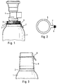
- Fig. 1 shows a conventional gas bottle 1 with a bottle neck ring 2, bottle cap thread 3 with backward rotation 4 and mounted bottle valve 5.
- a plastic ring 6 limited arranged flexible material.
- the plastic ring 6 has a tab 7 which is angled so that it is in contact with the bottle neck ring and the bottle shoulder.
- 2 shows a top view of the plastic ring 6 with tab 7 shown stretched and cast Data carrier 8.
- Fig. 3 shows the gas bottle 1 with a conical tool 9, which over the bottle cap thread is put up. With the help of the conical Tool 9, the plastic ring 6 simple and can be quickly pulled over the bottle cap thread.
- the inner diameter of the plastic ring is preferred 6 dimensioned so that the plastic ring 6 on the Back rotation is tight, but is still rotatable.
- the 1 to 3 shown variant of the invention is particularly suitable for such data carriers, which are provided with an annular transmission antenna are. This is then in the area of the outside diameter of the plastic ring 6, which if necessary enlarged and pulled down to the bottle shoulder can be. The tab 7 can do this omitted.
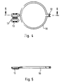
- a plastic ring 10 which has a high dimensional stability.
- the Plastic ring 10 is open on one side and is by means of a clip 12 closed endlessly. He also owns a developed tab 11, which is also by means of a clip 13 can be closed. This does it is possible to place the disk in the tab 11 if necessary exchange.
- Fig. 5 shows that the tab 11th is formed from two shells, which after clipping form a cavity for receiving the data carrier.
- All clips can only be destroyed by mechanical means be opened. If desired, the clips but can also be designed so that they can by means of a Special tools can be opened non-destructively.
- To assemble the plastic ring 10 none additional tools needed. Also in this embodiment is not after violent removal Reuse possible and misuse immediately recognizable.
- the plastic ring 10 can be fixed or can be rotated. The disk in the tab can be removed after violent opening either reuse it if only the plastic ring 10 is worn out or to recycle it.
- the plastic rings according to the invention stay on the bottle. Since she's the bottle shoulder don't cover them, they stay on the bottle shoulder hard-to-read information readable.
Landscapes
- Engineering & Computer Science (AREA)
- Mechanical Engineering (AREA)
- General Engineering & Computer Science (AREA)
- Physics & Mathematics (AREA)
- General Physics & Mathematics (AREA)
- Theoretical Computer Science (AREA)
- Filling Or Discharging Of Gas Storage Vessels (AREA)
- Details Of Rigid Or Semi-Rigid Containers (AREA)
- Facsimile Scanning Arrangements (AREA)
Description
- Fig. 1
- das Oberteil einer Gasflasche mit Kunststoffring und abgewinkelter Lasche zur Aufnahme des Datenträgers,
- Fig. 2
- den Kunststoffring mit Lasche,
- Fig. 3
- das Oberteil einer Gasflasche mit über das Flaschenkappengewinde gestülptem kegelförmigen Werkzeug zur Montage des Kunststoffringes,
- Fig. 4
- einen Kunststoffring, welcher durch Klipsung verschließbar ist,
- Fig. 5
- einen Schnitt A-A durch den Kunststoffring nach Fig. 4.
Claims (6)
- Gasflasche (1) mit einer Vorrichtung für die Aufnahme eines Datenträgers zur maschinenlesbaren Identifikation der Gasflasche (1), wobei die Vorrichtung einen Kunststoffring (6,10) umfaßt, der in einer Hinterdrehung (4) unterhalb des Flaschenkappengewindes (3) der Gasflasche (1) angeordnet ist, dadurch gekennzeichnet, daß der Datenträger als elektronischer Datenträger ausgeführt ist und in einer Lasche (7, 11) aufgenommen ist.
- Gasflasche nach Anspruch 1,
dadurch gekennzeichnet,
daß der Kunststoffring (6) aus begrenzt flexiblem Material besteht und einen Innendurchmesser besitzt, der gleich oder wenig größer als der Durchmesser der Hinterdrehung ist. - Gasflasche nach Anspruch 1,
dadurch gekennzeichnet,
daß der Kunststoffring (10) aus Material hoher Formstabilität besteht, offen ist und mittels einer Klipsung (12) verschließbar ist. - Gasflasche nach Anspruch 3,
dadurch gekennzeichnet,
daß die Klipsung (12) nicht zerstörungsfrei lösbar ist. - Gasflasche nach einem der Ansprüche 1 bis 4,
dadurch gekennzeichnet,
daß der Datenträger in die Lasche eingegossen ist. - Gasflasche nach einem der Ansprüche 1 bis 4,
dadurch gekennzeichnet,
daß die Lasche aus zwei durch Klipsung miteinander verschließbaren Halbschalen besteht.
daß die Lasche aus zwei durch Klipsung miteinander verschließbaren Halbschalen besteht.
Applications Claiming Priority (2)
| Application Number | Priority Date | Filing Date | Title |
|---|---|---|---|
| DE4409313 | 1994-03-18 | ||
| DE4409313A DE4409313C2 (de) | 1994-03-18 | 1994-03-18 | Vorrichtung für die Aufnahme elektronischer Datenträger für Gasflaschen |
Publications (2)
| Publication Number | Publication Date |
|---|---|
| EP0672859A1 EP0672859A1 (de) | 1995-09-20 |
| EP0672859B1 true EP0672859B1 (de) | 1999-08-04 |
Family
ID=6513185
Family Applications (1)
| Application Number | Title | Priority Date | Filing Date |
|---|---|---|---|
| EP95103023A Expired - Lifetime EP0672859B1 (de) | 1994-03-18 | 1995-03-03 | Vorrichtung für die Aufnahme elektronischer Datenträger für Gasflaschen |
Country Status (3)
| Country | Link |
|---|---|
| EP (1) | EP0672859B1 (de) |
| AT (1) | ATE182975T1 (de) |
| DE (2) | DE4409313C2 (de) |
Cited By (1)
| Publication number | Priority date | Publication date | Assignee | Title |
|---|---|---|---|---|
| USD500632S1 (en) | 2002-09-23 | 2005-01-11 | Talisman Designs, Llc | Stemware adornment |
Families Citing this family (12)
| Publication number | Priority date | Publication date | Assignee | Title |
|---|---|---|---|---|
| DE19540595A1 (de) * | 1995-10-31 | 1997-05-07 | Messer Griesheim Gmbh | Chipträger aus Kunststoff |
| DE19857717B4 (de) * | 1998-12-15 | 2012-08-02 | Air Liquide Deutschland Gmbh | Vorrichtung für die Aufnahme elektronischer Datenträger für Druckgasflaschen und entsprechende Druckgasflasche |
| DE19857722B4 (de) * | 1998-12-15 | 2012-08-02 | Air Liquide Deutschland Gmbh | Vorrichtung mit elektronischem Datenträger zur Identifikation und Kennzeichnung von Druckgasflaschen sowie entsprechende Druckgasflasche |
| DE19911032C5 (de) * | 1999-03-12 | 2006-10-05 | Air Liquide Deutschland Gmbh | Gasflaschen-Ventilschutzvorrichtung mit Transpondereinheit |
| DE19911033B4 (de) * | 1999-03-12 | 2008-05-21 | Air Liquide Deutschland Gmbh | Vorrichtung zur Datenübernahme bei Gruppen von Objekten |
| DE19911034C5 (de) * | 1999-03-12 | 2006-11-02 | Air Liquide Deutschland Gmbh | Haltevorrichtung mit austauschbarer Transpondereinheit |
| DE19915779B4 (de) * | 1999-04-08 | 2007-10-31 | Air Liquide Deutschland Gmbh | Abfüllstand zur Herstellung von Präzisionsgasgemischen |
| DE10062867A1 (de) * | 2000-12-16 | 2002-07-18 | Messer Griesheim Gmbh | Originalitätskennzeichnung für eine Druckgasflasche |
| DE10146261B4 (de) * | 2001-09-20 | 2008-05-29 | Air Liquide Deutschland Gmbh | Ventilschutzbügel |
| WO2007057847A2 (fr) * | 2005-11-15 | 2007-05-24 | Idtek Track-And-Trace Sa | Recipient metallique comprenant un transpondeur |
| DE102005058385A1 (de) * | 2005-12-06 | 2007-06-14 | CCS Technology, Inc., Wilmington | Transponderanordnung |
| DE102011016041A1 (de) | 2011-04-04 | 2012-10-04 | Messer Gaspack Gmbh | Kennungssystem für Druckgasflaschen |
Family Cites Families (9)
| Publication number | Priority date | Publication date | Assignee | Title |
|---|---|---|---|---|
| FR1512526A (fr) * | 1966-12-28 | 1968-02-09 | Automatisme Cie Gle | Procédé et dispositif de marquage d'un objet au moyen d'une piste magnétique |
| US4364043A (en) * | 1979-05-30 | 1982-12-14 | The University Of Adelaide | Efficient object identification system |
| GB2077555A (en) * | 1980-05-27 | 1981-12-16 | Standard Telephones Cables Ltd | Electronic tally apparatus |
| US4827643A (en) * | 1984-12-31 | 1989-05-09 | Aga Gas Central, Inc. | Identification device for a container |
| US5008661A (en) * | 1985-09-27 | 1991-04-16 | Raj Phani K | Electronic remote chemical identification system |
| DE3927195A1 (de) * | 1989-08-17 | 1991-02-21 | Guenter Sonntag | Kennzeichnungseinrichtung mit codemarkierungen aufweisenden datentraegern |
| US5029550A (en) * | 1990-11-29 | 1991-07-09 | Hopper Sr Richard L | Hydrant tag structure |
| FR2685519A1 (fr) * | 1991-12-20 | 1993-06-25 | Gemplus Card Int | Systeme pour l'identification de recipients et notamment de bouteilles de gaz. |
| CH686593A5 (de) * | 1992-01-10 | 1996-04-30 | Stoba Ag | Handschliessplombe. |
-
1994
- 1994-03-18 DE DE4409313A patent/DE4409313C2/de not_active Expired - Fee Related
-
1995
- 1995-03-03 DE DE59506497T patent/DE59506497D1/de not_active Expired - Fee Related
- 1995-03-03 AT AT95103023T patent/ATE182975T1/de not_active IP Right Cessation
- 1995-03-03 EP EP95103023A patent/EP0672859B1/de not_active Expired - Lifetime
Cited By (1)
| Publication number | Priority date | Publication date | Assignee | Title |
|---|---|---|---|---|
| USD500632S1 (en) | 2002-09-23 | 2005-01-11 | Talisman Designs, Llc | Stemware adornment |
Also Published As
| Publication number | Publication date |
|---|---|
| DE4409313A1 (de) | 1995-09-21 |
| ATE182975T1 (de) | 1999-08-15 |
| DE4409313C2 (de) | 2002-01-10 |
| DE59506497D1 (de) | 1999-09-09 |
| EP0672859A1 (de) | 1995-09-20 |
Similar Documents
| Publication | Publication Date | Title |
|---|---|---|
| EP0672859A1 (de) | Vorrichtung für die Aufnahme elektronischer Datenträger für Gasflaschen | |
| EP0772152B1 (de) | Chipträger aus Kunststoff | |
| DE2758437C2 (de) | Milchprobenflasche | |
| DE3634268A1 (de) | Werkstueckspanneinrichtung | |
| DE29701978U1 (de) | Schraubendreher mit Drehunterstützung | |
| DE69213741T2 (de) | Behälter zum bewahren von mindestens einer kontaktlinse | |
| EP0737541B1 (de) | Datenträger | |
| DE3525785C1 (de) | Buegelverschluss fuer das Filtergehaeuse eines Ansaugluftfilters | |
| DE10353338A1 (de) | Beschriftungsring | |
| DE4208690A1 (de) | Am deckel einer bandkassette anbringbare spulenfeder und verfahren zum loesbaren anbringen der feder an der kassette | |
| DE2753285A1 (de) | Plombe, insbesondere zum verplomben des zaehlwerksgehaeuses bei einem gaszaehler | |
| DE2803888C2 (de) | Vorrichtung zum Auffangen von Bohrmehl | |
| DE19848043C2 (de) | Dichtungsanordnung | |
| DE2919626A1 (de) | Verschluss fuer uhrarmband | |
| DE29710458U1 (de) | Wiederverwendbares Verschlußelement | |
| DE8913353U1 (de) | Magnethalter | |
| DE2634953A1 (de) | Kleingeldbehaelter | |
| EP3683470B1 (de) | Luftfeder mit einem kennzeichnungs- oder datenträger | |
| DD255155A1 (de) | Vorrichtung zur halterung eines schneideinsatzes fuer schneidraedchen | |
| DE8805386U1 (de) | Kunststoff-Behälter | |
| DE8905973U1 (de) | Aufbewahrungsvorrichtung | |
| DE321446C (de) | Kugelgesperre zum Festhalten von Deckeln an Gefaessen und der Gefaesse an einem Hauptkoerper | |
| DE202004003041U1 (de) | Vorrichtung zum Haltern von bedruckten Bogen | |
| DE69113458T2 (de) | Verbesserte behälter-klemme. | |
| DE2243258B2 (de) | Kunststoffluftfilter, insbesondere fuer brennkraftmaschinen |
Legal Events
| Date | Code | Title | Description |
|---|---|---|---|
| PUAI | Public reference made under article 153(3) epc to a published international application that has entered the european phase |
Free format text: ORIGINAL CODE: 0009012 |
|
| AK | Designated contracting states |
Kind code of ref document: A1 Designated state(s): AT BE CH DE FR GB LI NL |
|
| 17P | Request for examination filed |
Effective date: 19960320 |
|
| 17Q | First examination report despatched |
Effective date: 19971104 |
|
| GRAG | Despatch of communication of intention to grant |
Free format text: ORIGINAL CODE: EPIDOS AGRA |
|
| GRAG | Despatch of communication of intention to grant |
Free format text: ORIGINAL CODE: EPIDOS AGRA |
|
| GRAH | Despatch of communication of intention to grant a patent |
Free format text: ORIGINAL CODE: EPIDOS IGRA |
|
| GRAH | Despatch of communication of intention to grant a patent |
Free format text: ORIGINAL CODE: EPIDOS IGRA |
|
| GRAA | (expected) grant |
Free format text: ORIGINAL CODE: 0009210 |
|
| AK | Designated contracting states |
Kind code of ref document: B1 Designated state(s): AT BE CH DE FR GB LI NL |
|
| REF | Corresponds to: |
Ref document number: 182975 Country of ref document: AT Date of ref document: 19990815 Kind code of ref document: T |
|
| REG | Reference to a national code |
Ref country code: CH Ref legal event code: EP |
|
| REF | Corresponds to: |
Ref document number: 59506497 Country of ref document: DE Date of ref document: 19990909 |
|
| GBT | Gb: translation of ep patent filed (gb section 77(6)(a)/1977) |
Effective date: 19990823 |
|
| ET | Fr: translation filed | ||
| PLBE | No opposition filed within time limit |
Free format text: ORIGINAL CODE: 0009261 |
|
| STAA | Information on the status of an ep patent application or granted ep patent |
Free format text: STATUS: NO OPPOSITION FILED WITHIN TIME LIMIT |
|
| 26N | No opposition filed | ||
| REG | Reference to a national code |
Ref country code: GB Ref legal event code: IF02 |
|
| PGFP | Annual fee paid to national office [announced via postgrant information from national office to epo] |
Ref country code: GB Payment date: 20040303 Year of fee payment: 10 |
|
| PGFP | Annual fee paid to national office [announced via postgrant information from national office to epo] |
Ref country code: FR Payment date: 20040309 Year of fee payment: 10 |
|
| PGFP | Annual fee paid to national office [announced via postgrant information from national office to epo] |
Ref country code: NL Payment date: 20040310 Year of fee payment: 10 |
|
| PGFP | Annual fee paid to national office [announced via postgrant information from national office to epo] |
Ref country code: AT Payment date: 20040311 Year of fee payment: 10 |
|
| PGFP | Annual fee paid to national office [announced via postgrant information from national office to epo] |
Ref country code: CH Payment date: 20040317 Year of fee payment: 10 |
|
| PGFP | Annual fee paid to national office [announced via postgrant information from national office to epo] |
Ref country code: DE Payment date: 20040331 Year of fee payment: 10 |
|
| PGFP | Annual fee paid to national office [announced via postgrant information from national office to epo] |
Ref country code: BE Payment date: 20040519 Year of fee payment: 10 |
|
| PG25 | Lapsed in a contracting state [announced via postgrant information from national office to epo] |
Ref country code: GB Free format text: LAPSE BECAUSE OF NON-PAYMENT OF DUE FEES Effective date: 20050303 Ref country code: AT Free format text: LAPSE BECAUSE OF NON-PAYMENT OF DUE FEES Effective date: 20050303 |
|
| PG25 | Lapsed in a contracting state [announced via postgrant information from national office to epo] |
Ref country code: LI Free format text: LAPSE BECAUSE OF NON-PAYMENT OF DUE FEES Effective date: 20050331 Ref country code: CH Free format text: LAPSE BECAUSE OF NON-PAYMENT OF DUE FEES Effective date: 20050331 Ref country code: BE Free format text: LAPSE BECAUSE OF NON-PAYMENT OF DUE FEES Effective date: 20050331 |
|
| BERE | Be: lapsed |
Owner name: *MESSER GRIESHEIM G.M.B.H. Effective date: 20050331 |
|
| PG25 | Lapsed in a contracting state [announced via postgrant information from national office to epo] |
Ref country code: NL Free format text: LAPSE BECAUSE OF NON-PAYMENT OF DUE FEES Effective date: 20051001 Ref country code: DE Free format text: LAPSE BECAUSE OF NON-PAYMENT OF DUE FEES Effective date: 20051001 |
|
| REG | Reference to a national code |
Ref country code: CH Ref legal event code: PL |
|
| GBPC | Gb: european patent ceased through non-payment of renewal fee |
Effective date: 20050303 |
|
| PG25 | Lapsed in a contracting state [announced via postgrant information from national office to epo] |
Ref country code: FR Free format text: LAPSE BECAUSE OF NON-PAYMENT OF DUE FEES Effective date: 20051130 |
|
| NLV4 | Nl: lapsed or anulled due to non-payment of the annual fee |
Effective date: 20051001 |
|
| REG | Reference to a national code |
Ref country code: FR Ref legal event code: ST Effective date: 20051130 |
|
| BERE | Be: lapsed |
Owner name: *MESSER GRIESHEIM G.M.B.H. Effective date: 20050331 |