EP0672857A1 - Gelenkrohr - Google Patents
Gelenkrohr Download PDFInfo
- Publication number
- EP0672857A1 EP0672857A1 EP95103136A EP95103136A EP0672857A1 EP 0672857 A1 EP0672857 A1 EP 0672857A1 EP 95103136 A EP95103136 A EP 95103136A EP 95103136 A EP95103136 A EP 95103136A EP 0672857 A1 EP0672857 A1 EP 0672857A1
- Authority
- EP
- European Patent Office
- Prior art keywords
- articulated
- section
- sleeve
- joint
- pipe
- Prior art date
- Legal status (The legal status is an assumption and is not a legal conclusion. Google has not performed a legal analysis and makes no representation as to the accuracy of the status listed.)
- Granted
Links
Images
Classifications
-
- F—MECHANICAL ENGINEERING; LIGHTING; HEATING; WEAPONS; BLASTING
- F16—ENGINEERING ELEMENTS AND UNITS; GENERAL MEASURES FOR PRODUCING AND MAINTAINING EFFECTIVE FUNCTIONING OF MACHINES OR INSTALLATIONS; THERMAL INSULATION IN GENERAL
- F16L—PIPES; JOINTS OR FITTINGS FOR PIPES; SUPPORTS FOR PIPES, CABLES OR PROTECTIVE TUBING; MEANS FOR THERMAL INSULATION IN GENERAL
- F16L27/00—Adjustable joints; Joints allowing movement
- F16L27/02—Universal joints, i.e. with mechanical connection allowing angular movement or adjustment of the axes of the parts in any direction
- F16L27/04—Universal joints, i.e. with mechanical connection allowing angular movement or adjustment of the axes of the parts in any direction with partly-spherical engaging surfaces
-
- H—ELECTRICITY
- H02—GENERATION; CONVERSION OR DISTRIBUTION OF ELECTRIC POWER
- H02G—INSTALLATION OF ELECTRIC CABLES OR LINES, OR OF COMBINED OPTICAL AND ELECTRIC CABLES OR LINES
- H02G3/00—Installations of electric cables or lines or protective tubing therefor in or on buildings, equivalent structures or vehicles
- H02G3/02—Details
- H02G3/04—Protective tubing or conduits, e.g. cable ladders or cable troughs
- H02G3/0462—Tubings, i.e. having a closed section
- H02G3/0475—Tubings, i.e. having a closed section formed by a succession of articulated units
-
- H—ELECTRICITY
- H02—GENERATION; CONVERSION OR DISTRIBUTION OF ELECTRIC POWER
- H02G—INSTALLATION OF ELECTRIC CABLES OR LINES, OR OF COMBINED OPTICAL AND ELECTRIC CABLES OR LINES
- H02G9/00—Installations of electric cables or lines in or on the ground or water
- H02G9/06—Installations of electric cables or lines in or on the ground or water in underground tubes or conduits; Tubes or conduits therefor
Definitions
- the invention relates to a joint pipe for cable ducting or the like., Which is composed of individual pipes, the end pipes having a sleeve or an insertion end and spherical joints consisting of joint sleeves and joint balls are provided between the individual pipes, which are provided by a in the joint area arranged sealing element are sealed pressure-tight.
- Another flexible pipe bend with an outer bead provided in its socket area and an inner inlet surface can be found in DE-GM 92 16 784.5.
- the CH-PS 669 982 also shows a tight joint device for cylindrical tubes, wherein a ball joint is formed by two partially round and interlocking joint parts formed at the beginning and end of each pipe section.
- a joint device constructed in this way has the disadvantage of low strength on tensile and bending stresses.
- the invention has for its object to provide a generic articulated tube that has a pressure-tight, spherical connection for multi-element tubular elements and in which a release of the joint, or its joint ball, under stress during laying the cable ducting and possibly later loading, such as Traffic loads etc., is not possible and the articulated tube has a high strength against bending forces.
- the advantages achieved by the invention are, in particular, that the bending stiffness of the articulated pipe and thus the entire cable duct pipe run in the bend, compared to the known articulated pipes, is significantly increased and the deflection of the articulation through different stops, which represent the limit positions of the articulation, on certain dimension is limited and in that the pipe connection is locked in the joint, that is to say cannot be released. A non-destructive release of the joint connection is no longer possible. After all, economical production and installation of these articulated arches is an advantage.
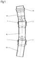
- FIG. 1 shows a pipe bend consisting of several pipes R1, R2, R3, the individual pipes R1, R2, R3 either having, like the pipe R1, a normal sleeve on one side and a spherical joint sleeve 1 on the other side, or like the tube R2, on one side a spherical joint ball 2 and on the other side a correspondingly designed joint sleeve 1. or as the tube R3, which, for example as the tube R1 or R2 is formed or has a joint ball on one side and an insertion end on the other side.
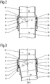
- the joint sleeve 1 is divided into two sections 1a, 1b with different inner radius r1, r2, both sections being separated by a shoulder 1c, which can be annular or frustoconical, for example.
- Section 1c serves as a stop for section 2b of the joint ball 2, which has an outer radius r1 which corresponds to the inner radius r1 of section 1a of the joint sleeve 1.
- the joint ball 2 also has a shoulder 2c between its two sections 2a, 2b, which also serves as a stop.
- the sealing ring 3 is inserted in a known manner into a corresponding groove of the joint ball 2 and seals the joint sleeve 1 with its section 1b, which has the smaller radius r2, from the section 2a of the joint ball, which also has the smaller radius r2, in a pressure-tight manner.
- This sealing ring 3 never leaves the region of the lesser Inner or outer radius r2, which ensures a permanent sealing effect.
- the angle is limited by the two shoulders 1c and 2c serving as stops between the larger and smaller radius sections' of the joint sleeve 1 and the joint ball 2.
- the insertion end of the pipe R2 can be provided below its joint ball with a ring 2d, in front of which the somewhat thickened sleeve edge 1g with its thickened edge 1e lies when the two pipes R1 and R2 are angled.
- section 2a of pipe R2 slides on inner casing section 1a and section 2b on inner casing section 1b of joint sleeve 1, if necessary. to the extreme position, where the movement of both tubes R1 and R2 is limited by paragraphs 1c and 1d, to which paragraph 2c strikes in the extreme position.
- the joint sleeve 1 and the joint ball 2 have a common center Z around which the rotational movement of the joint takes place.
- At least two pipes which are articulated to one another by an articulated sleeve 1 and an articulated ball 2, are necessary.
- at least three pipes R1, R2, R3 will be used, of which the middle pipe R2 has an articulated sleeve 1 and on one side the other side has a joint ball 2.
- the two end tubes R1 and R3 then accordingly have a known sleeve M on one side or a known insertion end (not shown in the figures).
- Section 2b can also be designed as an interrupted ring or partial ring, for example.
Landscapes
- Engineering & Computer Science (AREA)
- General Engineering & Computer Science (AREA)
- Mechanical Engineering (AREA)
- Architecture (AREA)
- Civil Engineering (AREA)
- Structural Engineering (AREA)
- Joints Allowing Movement (AREA)
- Rigid Pipes And Flexible Pipes (AREA)
- Supports For Pipes And Cables (AREA)
- Bending Of Plates, Rods, And Pipes (AREA)
- Non-Disconnectible Joints And Screw-Threaded Joints (AREA)
Abstract
Description
- Die Erfindung bezieht sich auf ein Gelenkrohr für Kabelkanalrohrzüge oder dergl., das aus Einzelrohren zusammengesetzt ist, wobei die endständigen Rohre eine Muffe bzw. ein Einsteckende aufweisen und aus Gelenkmuffen und Gelenkkugeln bestehende sphärische Gelenke zwischen den einzelnen Rohren vorgesehen sind, die durch ein im Gelenkbereich angeordnetes Dichtelement druckdicht abgedichtet sind.
- Der Einbau von Gelenkrohren in Kabelkanalrohrzüge empfiehlt sich immer dann, wenn diese um Hindernisse herum oder aus sonstigen Gründen im Bogen verlegt werden müssen und der Einbau von händisch vorgeformten Rohrbögen wegen deren starrer Abmessungen nicht möglich ist.
- Gattungsgemäße Gelenkrohre sind an sich bekannt. Beispielsweise offenbart die DE-OS 35 26 704 (EP 86 11 03 14.1) ein Gelenkelement für Kabelkanalrohrtrassen, das aus einem Rohrstück besteht, dessen Ende kalottenförmig aufgeweitet ist und in das ein Rohrstück eingeschoben ist, dessen Ende dieser kalottenförmigen Aufweitung entsprechend leicht verdickt ist und von innen nach außen leicht verjüngt verläuft. Außerdem ist eine Dichtung im Gelenkbereich vorgesehen und ein Überwurfring mit Anschlag am Ende der kalottenartigen Aufweitung. Ein zweiter Anschlag befindet sich innen an der Wurzel der kalottenförmigen Aufweitung. Ein Überwurfring ist bei mehrgliedrigen Bögen jedoch nicht anwendbar, da die Mittelteile beidseitig einen Bund mit größerem Außendurchmesser als der Innendurchmesser des Überwurfringes ist, aufweisen.
- Ein weiterer flexibler Rohrbogen mit einem in dessen Muffenbereich vorgesehenen äußeren Wulst und einer inneren Einlauffläche geht aus der DE-GM 92 16 784.5 hervor.
- Die CH-PS 669 982 zeigt ebenfalls eine dichte Gelenkvorrichtung für zylindrische Rohre, wobei durch zwei am Anfang und Ende eines jeden Rohrstückes angeformte, teilweise runde und ineinandergreifende Gelenkteile ein Kugelgelenk gebildet ist. Eine solcherart aufgebaute Gelenkvorrichtung weist den Nachteil geringer Festigkeit auf Zug- und Biegebeanspruchungen auf.
- Der Erfindung, wie sie in den Ansprüchen beschrieben ist, liegt die Aufgabe zugrunde, ein gattungsgemäßes Gelenkrohr zu schaffen, daß eine druckdichte, sphärische Verbindung für mehrgliedrige Rohrelemente aufweist und bei dem ein Herauslösen des Gelenkes, bzw. dessen Gelenkkugel, unter Beanspruchung bei der Verlegung des Kabelkanalrohrzuges und evtl. späterer Belastung, wie z.B. Verkehrslasten etc., nicht möglich ist und das Gelenkrohr eine hohe Festigkeit gegen Biegekräfte aufweist.
- Die mit der Erfindung erzielten Vorteile liegen insbesondere darin, daß die Biegesteifigkeit des Gelenkrohres und damit des gesamten im Bogen verlegten Kabelkanalrohrzuges, gegenüber den bekannten Gelenkrohren, wesentlich erhöht ist und die Auslenkung des Gelenkes durch unterschiedliche Anschläge, die die Grenzlagen des Gelenkes darstellen, auf ein sicheres Maß beschränkt ist und darin, daß die Rohrverbindung in dem Gelenk verrastet, also unlösbar ist. Eine zerstörungsfreie Lösung der Gelenkverbindung ist nicht mehr möglich. Schließlich ist eine wirtschaftliche Fertigung und Verlegung dieser Gelenkbogen von Vorteil.
- Die Erfindung ist nachstehend anhand eines in den Abbildungen dargestellten Ausführungsbeispieles näher erläutert.
- Es zeigt:
- Fig. 1
- einen Längsschnitt durch einen Rohrbogen.
- Fig. 2
- einen Längsschnitt durch ein Gelenk ohne und
- Fig. 3
- einen Längsschnitt durch ein Gelenk mit Auslenkung.
- Die Fig 1 zeigt einen Rohrbogen aus mehreren Rohren R1, R2, R3 bestehend, wobei die einzelnen Rohre R1, R2, R3 entweder, wie das Rohr R1, auf einer Seite eine normale Muffe und auf der anderen Seite eine sphärische Gelenkmuffe 1 besitzen, oder wie das Rohr R2, auf einer Seite eine sphärische Gelenkkugel 2 und auf der anderen Seite eine entsprechend ausgebildete Gelenkmuffe 1. bzw. wie das Rohr R3, das z.B. wie das Rohr R1 oder R2 ausgebildet ist oder auf einer Seite eine Gelenkkugel und auf der anderen Seite ein Einsteckende besitzt.
- Die Gelenkmuffe 1 ist in zwei Abschnitte 1a, 1b mit unterschiedlichem Innenradius r1, r2 aufgeteilt, wobei beide Abschnitte durch einen Absatz 1c, der beispielsweise ringförmig oder kegelstumpfförmig ausgebildet sein kann, getrennt sind. Der Abschnitt 1c dient als Anschlag für den Abschnitt 2b der Gelenkkugel 2, der einen Außenradius r1 aufweist, der dem Innenradius r1 des Abschnittes 1a der Gelenkmuffe 1 entspricht. Die Gelenkkugel 2 besitzt weiterhin einen Absatz 2c zwischen ihren beiden Abschnitten 2a, 2b, der gleichzeitig als Anschlag dient.
- Der Dichtring 3 ist in in bekannter Weise in eine entsprechende Nut der Gelenkkugel 2 eingesetzt und dichtet die Gelenkmuffe 1 mit ihrem Abschnitt 1b, der den geringeren Radius r2 aufweist gegenüber dem Abschnitt 2a der Gelenkkugel, der ebenfalls den geringeren Radius r2 aufweist druckdicht ab. Dieser Dichtring 3 verläßt beim Gleiten der Gelenkkugel 2 mit Ihrem Abschnitt 2a auf dem Abschnitt 1b der Gelenkmuffe 1 beim Abwinkeln der beiden Rohre R1 und R2 gegeneinander nie den Bereich der geringeren Innen- bzw. Außenradius r2, wodurch eine permanente Dichtwirkung gewährleistet ist. Die Begrenzung der Abwinklung geschieht durch die beiden als Anschläge dienenden Absätze 1c bzw. 2c zwischen den Abschnitten größeren und kleineren Radius' der Gelenkmuffe 1 und der Gelenkkugel 2.
- Das Einsteckende des Rohres R2 kann unterhalb dessen Gelenkkugel mit einem Ring 2d versehen sein, vor den sich beim Abwinkeln beider Rohre R1 und R2 gegeneinander der etwas verdickte Muffenrand 1g mit seinem verdickten Rand 1e legt.
- Beim Abwinkeln der beiden Rohre R1 und R2 bzw. R2 und R3 gegeneinander gleitet der Abschnitt 2a des Rohres R2 auf dem inneren Mantelabschnitt 1a und der Abschnitt 2b auf dem inneren Mantelabschnitt 1b der Gelenkmuffe 1 ggfl. bis zur Extremposition, wo die Bewegung beider Rohre R1 und R2 durch die Absätze 1c und 1d an die der Absatz 2c in der Extremposition anschlägt, begrenzt wird. Die Gelenkmuffe 1 und die Gelenkkugel 2 besitzen ein gemeinsames Zentrum Z, um das die Drehbewegung des Gelenkes erfolgt. Mit der kongruenten Ausbildung der Oberflächen der sich jeweils gegenüberliegenden sphärischen Abschnitte 1a-2b bzw. 1b-2a der beiden Rohre R1 und R2, bzw. R2 und R3 ist ein exaktes Gleiten, Begrenzen deren Bewegung bis in die Extrempositionen um den Auslenkungswinkel α und das Abdichten derselben gegeneinander gewährleistet. Der aus Festigkeitsgründen etwas verstärkte Muffenrand 1e legt sich in dieser Position vor den Ring 2d des Rohres R2. In der Fig. 1 sind drei Rohre R1, R2, und R3 dargestellt, von denen das Rohr R1 ein endständiges Rohr mit einer Anschlußmuffe M für ein weiters Rohr des Kabelkanalrohrzuges ohne Gelenk. Die Anzahl der Rohre in einem solchen Rohrgelenk hängt von dem Radius und der Länge des Bogens ab. Es sind mindestens zwei Rohre, die gelenkmäßig durch eine Gelenkmuffe 1 und eine Gelenkkugel 2 miteinander verbunden sind, notwendig. Im Normalfall werden jedoch mindestens drei Rohre R1,R2,R3 zum Einsatz kommen, von denen das mittlere Rohr R2 auf einer Seite eine Gelenkmuffe 1 und auf der anderen Seite eine Gelenkkugel 2 besitzt. Die beiden endständigen Rohre R1 bzw. R3 besitzen dann entsprechend auf einer Seite eine bekannte Muffe M oder ein, in den Abbildungen nicht dargestelltes, bekanntes Einsteckende.
- Die Verbindung zwischen einer Gelenkmuffe 1 und einer Gelenkkugel 2 ist, nach Eindrücken der Gelenkkugel in den Eintrittsquerschnitt der Gelenkmuffe und Einschnappen des Abschnittes 2b derselben hinter deren Absatz 1c der Gelenkmuffe 1 verrastet und unlösbar. Ein Lösen der Verbindung ist zerstörungsfrei nicht mehr möglich. Der Abschnitt 2b kann beispielsweise auch als unterbrochener Ring oder Teilring ausgebildet sein.
-
- D1
- Innendurchmesser des Rohres hinter Gelenkkugel
- D2
- Innendurchmesser des Rohres hinter Gelenkmuffe
- M
- normale Muffe
- R1
- Muffenrohr mit sphärischer Muffe und normaler Muffe
- R2
- Zwischenrohr mit sphärischer Muffe und Gelenkpfanne
- R3
- Rohr wie R2 oder mit Gelenkkugel und Einsteckende
- Z
- Mittelpunkt der Gelenkmuffe und der Gelenkkugel
- r1
- Radius
- r2
- Radius
- α
- Auslenkwinkel
- 1
- Gelenkmuffe
- 1a
- Abschnitt der Gelenkmuffe mit großem Innenradius
- 1b
- Abschnitt der Gelenkmuffe mit kleinem Innenradius
- 1c
- Absatz zwischen den Abschnitten der Gelenkmuffe
- 1d
- Absatz am Rohrende
- 1e
- Muffenrand
- 1f
- Eintrittsquerschnitt
- 1g
- Endabschnitt der Muffe
- 2
- Gelenkkugel
- 2a
- Abschnitt der Gelenkkugel mit kleinem Außenradius
- 2b
- Abschnitt der Gelenkkugel mit großem Außenradius
- 2c
- Absatz zwischen den Abschnitten der Gelenkkugel
- 2d
- Ring
- 3
- Dichtring
Claims (10)
- Gelenkrohr für Kabelkanalrohrzüge oder dergl., das aus Einzelrohren zusammengesetzt ist, wobei die endständigen Rohre eine Muffe bzw. ein Einsteckende aufweisen und aus Gelenkmuffen und Gelenkkugeln bestehende sphärische Gelenke zwischen den einzelnen Rohren vorgesehen sind, die durch ein im Gelenkbereich angeordnetes Dichtelement druckdicht abgedichtet sind, gekennzeichnet durch eine Kombination folgender Merkmale:i. die Gelenkmuffe (1) besitzt zwei unterschiedliche Abschnitte (1a, 1b)ii. die Gelenkkugel (2) besitzt zwei unterschiedliche Abschnitte (2a,2b),iii. die Radien (r1,r2) dieser Abschnitte (1a,1b) und (2a,2b) sind ungleich, die Abschnitte (1a) und (2b) weisen den gemeinsamen Innen- bzw. Außenradius (r1), wie die Abschnitte (1b) und (2a) den gleichen Innenradius bzw. Außenradius (r2) auf,iv. die Abschnitte (1a,2b) und (1b,2a) mit jeweils gleichen Radien liegen sich gegenüber,v. die Innenflächen der Abschnitte (1a,1b) der Gelenkmuffe (1) und die Außenflächen der Abschnitte (2a,2b) der Gelenkkugel (2) sind als Gleitflächen für den jeweils gegenüberliegenden Abschnitt ausgebildet.vi. Absätze (1c,2c) sind als Anschläge zwischen den Abschnitten (1a,1b) und (2a,2b) sowie ein Absatz (1d) zwischen dem Rohrkörper (R1) und dem Abschnitt (1a) vorgesehen,vii. die Gelenkmuffe (1) und die Gelenkkugel (2) sind miteinander unlösbar verrastet.
- Gelenkrohr nach Anspruch 1, dadurch gekennzeichnet, daß die beiden Abschnitte (1a),(1b) der Gelenkmuffe (1) ineinander so übergehen, daß der rohrseitige von einem Anschlag (1d) ausgehende Abschnitt (1a) den größeren Radius (r1), der muffenendseitige Abschnitt (1b) den kleineren Radius (r2) aufweist, die Gelenkkugel (2a) des Einsteckrohres (R2) einen rohrseitigen Abschnitt (2a) mit einer der Innenkontur des Abschnittes (1b) entsprechenden Außenkontur und einen äußeren ringförmigen Abschnitt (2b) mit einer der Innenkontur des Abschnittes (1a) entsprechenden Außenkontur besitzt, wobei die Gleitbewegung des Gelenkes in den beiden Endlagen mittels der Anschläge (1c) und (1d) für den ringförmigen Abschnitt (2b) der Gelenkkugel (2) begrenzt ist.
- Gelenkrohr nach Anspruch 1 und 2, dadurch gekennzeichnet, daß der Absatz (1c) kreisringförmig ausgebildet ist.
- Gelenkrohr nach Anspruch 1 bis 3, dadurch gekennzeichnet, daß der Absatz (1c) kegelstumpfförmig ausgebildet ist.
- Gelenkrohr nach Anspruch 1 bis 4, dadurch gekennzeichnet, daß am Einsteckrohrende (R2) ein Anschlag (2d) für den Endabschnitt (1g) mit einem Wulst (1e) der Gelenkmuffe (1) des Muffenrohres (R1) vorgesehen ist.
- Gelenkrohr nach Anspruch 1 bis 5, dadurch gekennzeichnet, daß der Innendurchmesser (D1) gleich dem Innendurchmesser (D2) ist und bei maximaler Auslenkung des Muffenrohres (R1) gegen das Einsteckrohrende (R2) um den Winkel α die innere Mantellinie der kelchförmigen Erweiterung der Gelenkkugel (2a) am Absatz (1d) in die innere Mantellinie des Muffenrohres (R1) mündet.
- Gelenkrohr nach Anspruch 1 bis 6, dadurch gekennzeichnet, daß der ringförmige Abschnitt (2b) der Gelenkkugel (2) auf der Innenkontur des inneren Abschnittes (1a) der Muffe (1) und die Gelenkkugel (2a) auf der Innenkontur des äußeren Abschnittes (1b) der Muffe (1) gleitet.
- Gelenkrohr nach Anspruch 1 bis 7, dadurch gekennzeichnet, daß dessen Teile aus einem in bestimmten Grenzen elastischen Kunststoff bestehen, und daß die Gelenkkugel (2) und die Gelenkmuffe (1) miteinander unlösbar verrasten, wobei mindestens der Außendurchmesser der Eintrittsquerschnitt (1f) der Gelenkmuffe (1) etwas kleiner als der Durchmesser der Gelenkkugel (2) ist und der Abschnitt (2b) der Gelenkkugel (2) hinter den Absatz (1c) der Gelenkmuffe (1) schnappt.
- Gelenkrohr nach Anspruch 1 bis 8, dadurch gekennzeichnet, daß der Abschnitt (2b) der Gelenkkugel (2) als unterbrochener Ring ausgebildet ist.
- Gelenkrohr nach Anspruch 1 bis 9, dadurch gekennzeichnet, daß der Absatz (1c) als unterbrochener Ring ausgebildet ist.
Priority Applications (1)
| Application Number | Priority Date | Filing Date | Title |
|---|---|---|---|
| SI9530221T SI0672857T1 (en) | 1994-03-16 | 1995-03-05 | Articulated pipe |
Applications Claiming Priority (2)
| Application Number | Priority Date | Filing Date | Title |
|---|---|---|---|
| DE4409022A DE4409022A1 (de) | 1994-03-16 | 1994-03-16 | Gelenkrohr |
| DE4409022 | 1994-03-16 |
Publications (2)
| Publication Number | Publication Date |
|---|---|
| EP0672857A1 true EP0672857A1 (de) | 1995-09-20 |
| EP0672857B1 EP0672857B1 (de) | 1999-02-10 |
Family
ID=6512998
Family Applications (1)
| Application Number | Title | Priority Date | Filing Date |
|---|---|---|---|
| EP95103136A Expired - Lifetime EP0672857B1 (de) | 1994-03-16 | 1995-03-05 | Gelenkrohr |
Country Status (12)
| Country | Link |
|---|---|
| EP (1) | EP0672857B1 (de) |
| AT (1) | ATE176719T1 (de) |
| CZ (1) | CZ283802B6 (de) |
| DE (2) | DE4409022A1 (de) |
| DK (1) | DK0672857T3 (de) |
| ES (1) | ES2128601T3 (de) |
| GR (1) | GR3030182T3 (de) |
| HU (1) | HU214391B (de) |
| PL (1) | PL175627B1 (de) |
| SI (1) | SI0672857T1 (de) |
| SK (1) | SK280147B6 (de) |
| TR (1) | TR28835A (de) |
Cited By (4)
| Publication number | Priority date | Publication date | Assignee | Title |
|---|---|---|---|---|
| WO2001096777A1 (en) * | 2000-06-12 | 2001-12-20 | Uponor Innovation Ab | Well |
| EP1388700A1 (de) * | 2002-08-06 | 2004-02-11 | Reiku GmbH | Gelenkiges Gliederrohr |
| EP1950482A1 (de) | 2006-12-18 | 2008-07-30 | Carl Freudenberg KG | Leitungsanordnung mit einer Dichtung im Überlappungsbereich |
| EP2873899A1 (de) * | 2013-11-14 | 2015-05-20 | ContiTech MGW GmbH | Kupplungssystem zum Verbinden von zwei Fluidleitungen |
Families Citing this family (6)
| Publication number | Priority date | Publication date | Assignee | Title |
|---|---|---|---|---|
| DE19608767A1 (de) * | 1996-03-07 | 1997-09-11 | Abb Patent Gmbh | Kombination zwischen einem Stutzen und einem daran anschließenden Rohr |
| RU2162561C1 (ru) * | 1999-06-01 | 2001-01-27 | Санкт-Петербургский государственный горный институт им. Г.В. Плеханова (Технический университет) | Шарнирное соединение гибкого трубопровода |
| DE20305462U1 (de) | 2003-04-04 | 2003-06-12 | AHMTEC GmbH, 26789 Leer | Protektor für Kabel und Rohrleitungen |
| DE202021104279U1 (de) * | 2021-08-10 | 2023-03-28 | REHAU Industries SE & Co. KG | Abdeckvorrichtung zum Abdecken einer Verbindungsstelle von medienführenden Rohrendabschnitten |
| DE202021104281U1 (de) * | 2021-08-10 | 2023-03-28 | REHAU Industries SE & Co. KG | Abdeckvorrichtung zum Abdecken einer Verbindungsstelle von medienführenden Rohrendabschnitten |
| DE202021104278U1 (de) * | 2021-08-10 | 2022-12-12 | REHAU Industries SE & Co. KG | Abdeckvorrichtung zum Abdecken einer Verbindungsstelle von medienführenden Rohrendabschnitten |
Citations (2)
| Publication number | Priority date | Publication date | Assignee | Title |
|---|---|---|---|---|
| GB2156932A (en) * | 1984-03-30 | 1985-10-16 | Iracroft Ltd | Ball joint pipe coupling |
| EP0213384A1 (de) * | 1985-07-25 | 1987-03-11 | Thyssen Plastik Anger Kg | Gelenkelement für Rohre oder dergleichen |
Family Cites Families (5)
| Publication number | Priority date | Publication date | Assignee | Title |
|---|---|---|---|---|
| US1714563A (en) * | 1926-08-06 | 1929-05-28 | Clemens A Kiel | Flexible ball-and-socket pipe joint |
| DE1907640U (de) * | 1961-08-16 | 1964-12-31 | Montaplast G M B H | Rohrverbindung. |
| DE1881345U (de) * | 1963-08-16 | 1963-10-24 | Steinzeug Und Kunststoffwarenf | Kugelgelenkverbindung fuer rohre od. dgl. aus kunststoff. |
| SU422914A1 (ru) * | 1972-03-31 | 1974-04-05 | В. Б. Дмитриев, И. К. Джураев , М. Л. Толчинский Государственное специальное конструкторское бюро ирригации | Соединение труб |
| JPS5635532B2 (de) * | 1973-10-15 | 1981-08-18 |
-
1994
- 1994-03-16 DE DE4409022A patent/DE4409022A1/de not_active Withdrawn
-
1995
- 1995-03-05 EP EP95103136A patent/EP0672857B1/de not_active Expired - Lifetime
- 1995-03-05 ES ES95103136T patent/ES2128601T3/es not_active Expired - Lifetime
- 1995-03-05 AT AT95103136T patent/ATE176719T1/de active
- 1995-03-05 DK DK95103136T patent/DK0672857T3/da active
- 1995-03-05 DE DE59505061T patent/DE59505061D1/de not_active Expired - Lifetime
- 1995-03-05 SI SI9530221T patent/SI0672857T1/xx unknown
- 1995-03-07 PL PL95307551A patent/PL175627B1/pl unknown
- 1995-03-10 CZ CZ95624A patent/CZ283802B6/cs unknown
- 1995-03-14 HU HU9500771A patent/HU214391B/hu unknown
- 1995-03-14 SK SK331-95A patent/SK280147B6/sk unknown
- 1995-03-16 TR TR00272/95A patent/TR28835A/xx unknown
-
1999
- 1999-05-10 GR GR990401268T patent/GR3030182T3/el unknown
Patent Citations (2)
| Publication number | Priority date | Publication date | Assignee | Title |
|---|---|---|---|---|
| GB2156932A (en) * | 1984-03-30 | 1985-10-16 | Iracroft Ltd | Ball joint pipe coupling |
| EP0213384A1 (de) * | 1985-07-25 | 1987-03-11 | Thyssen Plastik Anger Kg | Gelenkelement für Rohre oder dergleichen |
Cited By (4)
| Publication number | Priority date | Publication date | Assignee | Title |
|---|---|---|---|---|
| WO2001096777A1 (en) * | 2000-06-12 | 2001-12-20 | Uponor Innovation Ab | Well |
| EP1388700A1 (de) * | 2002-08-06 | 2004-02-11 | Reiku GmbH | Gelenkiges Gliederrohr |
| EP1950482A1 (de) | 2006-12-18 | 2008-07-30 | Carl Freudenberg KG | Leitungsanordnung mit einer Dichtung im Überlappungsbereich |
| EP2873899A1 (de) * | 2013-11-14 | 2015-05-20 | ContiTech MGW GmbH | Kupplungssystem zum Verbinden von zwei Fluidleitungen |
Also Published As
| Publication number | Publication date |
|---|---|
| CZ283802B6 (cs) | 1998-06-17 |
| TR28835A (tr) | 1997-07-17 |
| ATE176719T1 (de) | 1999-02-15 |
| SI0672857T1 (en) | 1999-06-30 |
| HUT70825A (en) | 1995-11-28 |
| HU9500771D0 (en) | 1995-04-28 |
| ES2128601T3 (es) | 1999-05-16 |
| PL175627B1 (pl) | 1999-01-29 |
| GR3030182T3 (en) | 1999-08-31 |
| DE4409022A1 (de) | 1995-09-21 |
| SK33195A3 (en) | 1995-10-11 |
| EP0672857B1 (de) | 1999-02-10 |
| PL307551A1 (en) | 1995-09-18 |
| SK280147B6 (sk) | 1999-09-10 |
| DK0672857T3 (da) | 1999-09-20 |
| DE59505061D1 (de) | 1999-03-25 |
| CZ62495A3 (en) | 1995-12-13 |
| HU214391B (hu) | 1998-03-30 |
Similar Documents
| Publication | Publication Date | Title |
|---|---|---|
| DE69804365T2 (de) | Teleskopische und schwenkbare Rohrverbindung | |
| DE69916290T2 (de) | Rohrdichtung mit eingelassenem ring | |
| DE10060120B4 (de) | Kugelgleichlaufgelenk als Gegenbahngelenk | |
| DE10060220C2 (de) | Gleichlauffestgelenk | |
| EP0558071A1 (de) | Koaxialrohr | |
| CH648159A5 (de) | Rohrverbinder fuer kabelschutzrohre. | |
| EP0672857B1 (de) | Gelenkrohr | |
| DE10304156B4 (de) | Gegenbahngelenk mit verbessertem Käfig | |
| DE2615428A1 (de) | Rohrdurchfuehrung | |
| DE29707800U1 (de) | Winkelverbinder | |
| DE69322955T2 (de) | Beschichtungsrohr | |
| DE3117225C2 (de) | ||
| DE9404481U1 (de) | Gelenkrohr | |
| DE102008004152A1 (de) | Rohrleitung mit einem Anschlussstück | |
| EP0213384A1 (de) | Gelenkelement für Rohre oder dergleichen | |
| DE4319888C2 (de) | Rohrförmige Ummantelung für ein Zugglied | |
| DE19536703A1 (de) | Rohr, insbesondere Kunststoffrohr, und Rohrverbindung aus solchen Rohren | |
| DE102006029705B4 (de) | Rohrverbindung und Rohrverbindungssystem mit derartigen Rohrverbindungen | |
| DE4010234A1 (de) | Rohrverbindung | |
| EP0131086B1 (de) | Dachentlüftungsrohr | |
| DE2553388A1 (de) | Vorgefertigter kanalisationsschacht mit rohranschlusstuecken | |
| EP1046854A2 (de) | Muffenverbindung zur Verbindung zweier Rohre und Verriegelungsvorrichtung für eine Muffenverbindung | |
| DE3402198A1 (de) | Schutzrohr fuer elektrische leitungen | |
| DE3244722C1 (de) | Flexible Lutte | |
| DE9201997U1 (de) | Biegsames Rohr oder Rohrformstück |
Legal Events
| Date | Code | Title | Description |
|---|---|---|---|
| PUAI | Public reference made under article 153(3) epc to a published international application that has entered the european phase |
Free format text: ORIGINAL CODE: 0009012 |
|
| AK | Designated contracting states |
Kind code of ref document: A1 Designated state(s): AT BE CH DE DK ES FR GB GR IE IT LI LU MC NL PT SE |
|
| RAX | Requested extension states of the european patent have changed |
Free format text: LT PAYMENT 950305;SI PAYMENT 950305 |
|
| 17P | Request for examination filed |
Effective date: 19950926 |
|
| 17Q | First examination report despatched |
Effective date: 19961218 |
|
| RAP1 | Party data changed (applicant data changed or rights of an application transferred) |
Owner name: THYSSEN POLYMER GMBH |
|
| RAP1 | Party data changed (applicant data changed or rights of an application transferred) |
Owner name: GABO SYSTEMTECHNIK GMBH |
|
| GRAG | Despatch of communication of intention to grant |
Free format text: ORIGINAL CODE: EPIDOS AGRA |
|
| GRAG | Despatch of communication of intention to grant |
Free format text: ORIGINAL CODE: EPIDOS AGRA |
|
| GRAH | Despatch of communication of intention to grant a patent |
Free format text: ORIGINAL CODE: EPIDOS IGRA |
|
| GRAH | Despatch of communication of intention to grant a patent |
Free format text: ORIGINAL CODE: EPIDOS IGRA |
|
| GRAA | (expected) grant |
Free format text: ORIGINAL CODE: 0009210 |
|
| AK | Designated contracting states |
Kind code of ref document: B1 Designated state(s): AT BE CH DE DK ES FR GB GR IE IT LI LU MC NL PT SE |
|
| AX | Request for extension of the european patent |
Free format text: LT PAYMENT 950305;SI PAYMENT 950305 |
|
| REF | Corresponds to: |
Ref document number: 176719 Country of ref document: AT Date of ref document: 19990215 Kind code of ref document: T |
|
| REG | Reference to a national code |
Ref country code: CH Ref legal event code: EP |
|
| REG | Reference to a national code |
Ref country code: IE Ref legal event code: FG4D Free format text: GERMAN |
|
| REF | Corresponds to: |
Ref document number: 59505061 Country of ref document: DE Date of ref document: 19990325 |
|
| ET | Fr: translation filed | ||
| REG | Reference to a national code |
Ref country code: CH Ref legal event code: NV Representative=s name: HIEBSCH & PEEGE AG PATENTANWAELTE |
|
| ITF | It: translation for a ep patent filed | ||
| REG | Reference to a national code |
Ref country code: ES Ref legal event code: FG2A Ref document number: 2128601 Country of ref document: ES Kind code of ref document: T3 |
|
| GBT | Gb: translation of ep patent filed (gb section 77(6)(a)/1977) |
Effective date: 19990511 |
|
| REG | Reference to a national code |
Ref country code: DK Ref legal event code: T3 |
|
| PG25 | Lapsed in a contracting state [announced via postgrant information from national office to epo] |
Ref country code: MC Free format text: LAPSE BECAUSE OF NON-PAYMENT OF DUE FEES Effective date: 19990930 |
|
| REG | Reference to a national code |
Ref country code: IE Ref legal event code: FD4D |
|
| PLBE | No opposition filed within time limit |
Free format text: ORIGINAL CODE: 0009261 |
|
| STAA | Information on the status of an ep patent application or granted ep patent |
Free format text: STATUS: NO OPPOSITION FILED WITHIN TIME LIMIT |
|
| 26N | No opposition filed | ||
| REG | Reference to a national code |
Ref country code: IE Ref legal event code: FD4D Ref document number: Errata: Incorrectly Country of ref document: IE |
|
| REG | Reference to a national code |
Ref country code: IE Ref legal event code: FD4D Ref document number: ERRATA: Incorrectly Country of ref document: IE |
|
| PGFP | Annual fee paid to national office [announced via postgrant information from national office to epo] |
Ref country code: PT Payment date: 20010115 Year of fee payment: 7 |
|
| PGFP | Annual fee paid to national office [announced via postgrant information from national office to epo] |
Ref country code: GB Payment date: 20010119 Year of fee payment: 7 |
|
| PGFP | Annual fee paid to national office [announced via postgrant information from national office to epo] |
Ref country code: GR Payment date: 20010131 Year of fee payment: 7 |
|
| REG | Reference to a national code |
Ref country code: GB Ref legal event code: IF02 |
|
| PG25 | Lapsed in a contracting state [announced via postgrant information from national office to epo] |
Ref country code: GB Free format text: LAPSE BECAUSE OF NON-PAYMENT OF DUE FEES Effective date: 20020305 |
|
| PG25 | Lapsed in a contracting state [announced via postgrant information from national office to epo] |
Ref country code: PT Free format text: LAPSE BECAUSE OF NON-PAYMENT OF DUE FEES Effective date: 20020930 |
|
| PG25 | Lapsed in a contracting state [announced via postgrant information from national office to epo] |
Ref country code: GR Free format text: LAPSE BECAUSE OF NON-PAYMENT OF DUE FEES Effective date: 20021007 |
|
| GBPC | Gb: european patent ceased through non-payment of renewal fee |
Effective date: 20020305 |
|
| REG | Reference to a national code |
Ref country code: PT Ref legal event code: MM4A Free format text: LAPSE DUE TO NON-PAYMENT OF FEES Effective date: 20020930 |
|
| REG | Reference to a national code |
Ref country code: SI Ref legal event code: IF |
|
| REG | Reference to a national code |
Ref country code: CH Ref legal event code: PFA Owner name: GABO SYSTEMTECHNIK GMBH Free format text: GABO SYSTEMTECHNIK GMBH#BAYERWALDSTRASSE 18#94327 BOGEN (DE) -TRANSFER TO- GABO SYSTEMTECHNIK GMBH#BAYERWALDSTRASSE 18#94327 BOGEN (DE) |
|
| PGFP | Annual fee paid to national office [announced via postgrant information from national office to epo] |
Ref country code: NL Payment date: 20140320 Year of fee payment: 20 Ref country code: CH Payment date: 20140324 Year of fee payment: 20 Ref country code: DE Payment date: 20140310 Year of fee payment: 20 Ref country code: IE Payment date: 20140324 Year of fee payment: 20 Ref country code: LU Payment date: 20140324 Year of fee payment: 20 Ref country code: DK Payment date: 20140325 Year of fee payment: 20 Ref country code: SE Payment date: 20140324 Year of fee payment: 20 |
|
| PGFP | Annual fee paid to national office [announced via postgrant information from national office to epo] |
Ref country code: IT Payment date: 20140327 Year of fee payment: 20 Ref country code: FR Payment date: 20140319 Year of fee payment: 20 Ref country code: AT Payment date: 20140320 Year of fee payment: 20 Ref country code: ES Payment date: 20140324 Year of fee payment: 20 |
|
| PGFP | Annual fee paid to national office [announced via postgrant information from national office to epo] |
Ref country code: BE Payment date: 20140320 Year of fee payment: 20 |
|
| REG | Reference to a national code |
Ref country code: DE Ref legal event code: R071 Ref document number: 59505061 Country of ref document: DE |
|
| REG | Reference to a national code |
Ref country code: DK Ref legal event code: EUP Effective date: 20150305 |
|
| REG | Reference to a national code |
Ref country code: NL Ref legal event code: V4 Effective date: 20150305 |
|
| REG | Reference to a national code |
Ref country code: CH Ref legal event code: PL |
|
| REG | Reference to a national code |
Ref country code: AT Ref legal event code: MK07 Ref document number: 176719 Country of ref document: AT Kind code of ref document: T Effective date: 20150305 |
|
| REG | Reference to a national code |
Ref country code: SE Ref legal event code: EUG |
|
| REG | Reference to a national code |
Ref country code: IE Ref legal event code: MK9A |
|
| REG | Reference to a national code |
Ref country code: ES Ref legal event code: FD2A Effective date: 20150826 |
|
| PG25 | Lapsed in a contracting state [announced via postgrant information from national office to epo] |
Ref country code: IE Free format text: LAPSE BECAUSE OF EXPIRATION OF PROTECTION Effective date: 20150305 |
|
| PG25 | Lapsed in a contracting state [announced via postgrant information from national office to epo] |
Ref country code: ES Free format text: LAPSE BECAUSE OF EXPIRATION OF PROTECTION Effective date: 20150306 |