EP0672012B1 - Bulk material container with an emptying arrangement - Google Patents
Bulk material container with an emptying arrangement Download PDFInfo
- Publication number
- EP0672012B1 EP0672012B1 EP93922878A EP93922878A EP0672012B1 EP 0672012 B1 EP0672012 B1 EP 0672012B1 EP 93922878 A EP93922878 A EP 93922878A EP 93922878 A EP93922878 A EP 93922878A EP 0672012 B1 EP0672012 B1 EP 0672012B1
- Authority
- EP
- European Patent Office
- Prior art keywords
- holder
- webs
- container
- framework
- roof
- Prior art date
- Legal status (The legal status is an assumption and is not a legal conclusion. Google has not performed a legal analysis and makes no representation as to the accuracy of the status listed.)
- Expired - Lifetime
Links
Images


Classifications
-
- B—PERFORMING OPERATIONS; TRANSPORTING
- B65—CONVEYING; PACKING; STORING; HANDLING THIN OR FILAMENTARY MATERIAL
- B65D—CONTAINERS FOR STORAGE OR TRANSPORT OF ARTICLES OR MATERIALS, e.g. BAGS, BARRELS, BOTTLES, BOXES, CANS, CARTONS, CRATES, DRUMS, JARS, TANKS, HOPPERS, FORWARDING CONTAINERS; ACCESSORIES, CLOSURES, OR FITTINGS THEREFOR; PACKAGING ELEMENTS; PACKAGES
- B65D90/00—Component parts, details or accessories for large containers
- B65D90/54—Gates or closures
- B65D90/62—Gates or closures having closure members movable out of the plane of the opening
- B65D90/626—Gates or closures having closure members movable out of the plane of the opening having a linear motion
-
- B—PERFORMING OPERATIONS; TRANSPORTING
- B65—CONVEYING; PACKING; STORING; HANDLING THIN OR FILAMENTARY MATERIAL
- B65F—GATHERING OR REMOVAL OF DOMESTIC OR LIKE REFUSE
- B65F1/00—Refuse receptacles; Accessories therefor
- B65F1/12—Refuse receptacles; Accessories therefor with devices facilitating emptying
- B65F1/125—Features allowing the receptacle to be lifted and emptied by its bottom
Landscapes
- Engineering & Computer Science (AREA)
- Mechanical Engineering (AREA)
- Auxiliary Methods And Devices For Loading And Unloading (AREA)
- Filling Or Emptying Of Bunkers, Hoppers, And Tanks (AREA)
- Portable Outdoor Equipment (AREA)
- Control And Other Processes For Unpacking Of Materials (AREA)
Abstract
Description
Die vorliegende Erfindung betrifft einen Container für Schüttgüter, welcher über eine Bodenentleerung verfügt, nach dem Oberbegriff des Patentanspruches 1. Solche Container werden vorzugsweise für Massenschüttgüter eingesetzt wie Sand, Kies, Koks und dergleichen.The present invention relates to a container for bulk goods, which has a floor drain, according to the preamble of
Aus der Patentliteratur und dem technischen Einsatz sind grundsätzlich zwei Typen von Containern nach dem Oberbegriff bekannt: Einerseits solche, die vorzugsweise aus der Bewirtschaftung von Abfall-Glas bekannt sind (beispielsweise nach WO-A-93/12018), anderseits solche, die meist als Eisenbahnwaggon-Aufbauten ausgeführt sind und über eine klappenbetätigte Entleerungsöffnung verfügen.Basically, two types of containers are known from the patent literature and technical use according to the preamble: On the one hand, those that are preferably known from the management of waste glass (for example, according to WO-A-93/12018), and on the other hand, those that are mostly known as Railway wagon bodies are designed and have a flap-operated emptying opening.
Abfall-Glas-Container verfügen in der Regel über einzelne Einwerföffnungen vorzugsweise für Flaschen, stehen einige Zeit an einer Wertstoffsammelstelle, werden durch besondere Lastwagen abgeführt und durch leere Container ersetzt. Die Leerung geschieht entweder im Glaswerk oder auf einer Bahnstation durch Anheben der Container-Hülle oder Absenken des pyramiden- oder kegelförmig ausgestalteten Bodens. Die Ausbildung solcher Container ist in Uebereinstimmung mit den Belade- und Entlade-Geschwindigkeiten, und der Menge des Sammelgutes.Waste glass containers generally have individual drop-in openings, preferably for bottles, stand at a recycling point for some time, are removed by special trucks and replaced by empty containers. The emptying takes place either in the glassworks or on a train station by lifting the container shell or lowering the pyramid or conical bottom. The formation of such containers is in accordance with the loading and unloading speeds, and the amount of the bulk goods.
Beim zweiten erwähnten Typ sind sowohl Beladen als auch Entladen durch einen hohen zeitlichen Massenstrom gekennzeichnet. Für das Entladen sind zudem besondere Vorrichtungen, sog. Bahngossen notwendig. Für die dem Beladen vorangehende und die dem Entladen nachfolgende Lagerung sind besondere Lagervorrichtungen, Silos erforderlich. Die Verwendung von solchen genannten als Waggonaufbau gestalteten Schüttgut-Containern verlangen also hohe Kapital-Aufwendungen, für die Container selbst, für Silos und für die Bahngossen. Die Verwendungseinheit ist zudem immer mindestens ein ganzer Waggon, selbst wenn dieser nur zum Teil gefüllt werden soll. Beim Umlad auf Lastwagen für eine allfällige Feinverteilung sind weitere Einrichtungen und entweder ein spezieller Lastwagen oder besondere Aufbauten vorzusehen.In the second type mentioned, both loading and unloading are characterized by a high temporal mass flow. Special devices, so-called railway gutters, are also required for unloading. Special storage devices and silos are required for the storage prior to loading and subsequent storage after unloading. The use of such bulk goods containers designed as wagon bodies therefore requires high capital expenditure, for the containers themselves, for silos and for the railway gutters. The unit of use is also always at least one whole wagon, even if it is only to be partially filled. When reloading onto trucks for any fine distribution, additional facilities and either a special truck or special superstructures must be provided.
In GB-A-1'071'600 wird ein Container beschrieben, der über eine Bodenentleerung verfügt. Er enthält in seinem unteren Teil eine Vielzahl von dachförmigen Stegen sowie einen weiteren Bestandteil, der ebenfalls eine Vielzahl von dachförmigen Stegen aufweist, welche so angeordnet sind, dass sie zwischen den dachförmigen Stegen des Behälters durchlaufen, dergestalt, dass wenn der Behälter in Bezug auf den Bestandteil in einer bestimmten Stellung ist, die Stege des Bestandteils und die Stege des Behälters nebeneinander zu liegen kommen und der Behälter damit verschlossen ist. Der Nachteil dieser Vorrichtung besteht darin, dass der Container nur auf speziell dafür vorgesehenen Entladestationen entleert werden kann und der Bestandteil störungsanfällige bewegliche Teile enthält. Die Aufgabe, die mit der vorliegenden Erfindung gelöst wird, besteht darin, einen Container mit Bodenentleerung für Schüttgüter zu schaffen, der ohne Klappen-Einrichtung oder andere bewegliche Teile im Verschlussbereich funktioniert, der in verschiedenen Grössen - auch als ISO - Norm - Container, gebaut werden kann, der die Notwendigkeit für Silos überflüssig macht oder doch sehr einschränkt, in seinem Aufbau einfach, robust und wartungsfreundlich ist, für die Entleerung keinerlei angebaute elektrischen, pneumatischen und/oder hydraulischen Hilfsvorrichtungen aufweist und zur Entladung nicht auf speziell dafür vorgesehene Entladestationen angewiesen ist.GB-A-1'071'600 describes a container that has a floor drain. It contains in its lower part a multiplicity of roof-shaped webs and a further component, which also has a multiplicity of roof-shaped webs, which are arranged such that they pass between the roof-shaped webs of the container, in such a way that when the container is in relation to the Part is in a certain position, the webs of the component and the webs of the container come to lie next to each other and the container is closed with it. The disadvantage of this device is that the container can only be emptied at specially provided unloading stations and the component contains moving parts that are susceptible to malfunction. The object that is achieved with the present invention is to create a container with floor emptying for bulk goods that works without a flap device or other moving parts in the closure area, and that is built in different sizes - also as an ISO standard container can, which makes the need for silos superfluous or very limited, its structure is simple, robust and easy to maintain, has no attached electrical, pneumatic and / or hydraulic auxiliary devices for emptying and does not rely on specially designed unloading stations for unloading .
Die Lösung der gestellten Aufgabe ist wiedergegeben im kennzeichnenden Teil des Patentanspruchs 1 hinsichtlich seiner Hauptmerkmale, in den Patentansprüchen 2 bis 10 hinsichtlich besonderer Ausbildungen.
Die erfindungsgemässe Vorrichtung ist anhand der beigefügten Zeichnungen näher erläutert. Es zeigen
- Fig. 1
- Eine perspektivische Ansicht des erfindungsgemässen Containers von aussen,
- Fig. 2
- einen Längsschnitt durch den Container im verschlossenen Zustand,
- Fif. 3
- einen Längsschnitt durch den Container im offenen Zustand,
- Fig. 4
- eine perspektivische Ansicht des Containers von innen,
- Fig. 5
- ein Detail, teilweise im Schnitt,
- Fig. 6
- eine Detailansicht von oben,
- Fig. 7
- eine Draufsicht auf eine Variante.
The device according to the invention is explained in more detail with reference to the accompanying drawings. Show it
- Fig. 1
- A perspective view of the container according to the invention from the outside,
- Fig. 2
- a longitudinal section through the container in the closed state,
- Fif. 3rd
- a longitudinal section through the container in the open state,
- Fig. 4
- a perspective view of the container from the inside,
- Fig. 5
- a detail, partly in section,
- Fig. 6
- a detailed view from above,
- Fig. 7
- a top view of a variant.
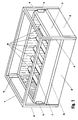
In Fig. 1 ist der erfindungsgemässe Container in einer perspektivischen Ansicht dargestellt. Er besteht aus einem, beispielsweise aus Vierkantrohren zusammengeschweissten, Rahmen 1 mit vier vertikalen Streben 4, welche an ihren oberen Enden durch horizontale Streben 20 verbunden sind. Im unteren Teil des Rahmens 1 sind auf allen vier Seiten starke Seitenbleche 2 eingeschweisst. In diesem Rahmen 1 ist ein Behälter 3 so eingelassen, dass er entlang der vertikalen Streben 4 beweglich ist. Dazu sind in den Ecken des Behälters 3 Führungen 5 angebracht, welche anhand von Fig. 6 und 7 näher beschrieben sind. Im Inneren des Behälters 3 sind dachförmige Verbindungsstreben 6 sichtbar, welche die Längswände des Behälters 3 verbinden und versteifen. Ebenso ist der obere Rand des Behälters 3 zur Versteifung mit einer dachförmigen Leiste 7 beispielsweise durch Schweissen verbunden, welche gleichzeitig als Abweisvorrichtung dient, damit kein Schüttgut auf dem Rande liegen bleibt. Rund um den Behälter 3 läuft zudem - mit ihm verschweisst - eine weitere, nach unten und aussen geneigte Leiste 8, welche, in der Position des Containers nach Fig. 1, den oberen Rand der Seitenbleche 2 - und damit auch den Zwischenraum zwischen Seitenblechen 2 und Behälter 3 - abdeckt. Anstelle von ebenen Seitenblechen 2 - wie dargestellt - können im Sinne der Erfindung auch flache Hohlprofile oder Rippenbleche verwendet werden, deren Rippen in horizontaler Richtung verlaufen.In Fig. 1 the container according to the invention is shown in a perspective view. It consists of a
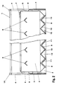
Fig. 2 zeigt den Container von Fig. 1 im Längsschnitt. Dieser zeigt, dass der Behälter 3 in seinem unteren Teil pyramidenstumpfförmig eingezogen ist. Die Bodenöffnung des Behälters 3 ist verschlossen durch eine Vielzahl von dachförmigen Stegen 9, 10. Die in Fig. 2 vertikal schraffierten Stege 9 sind mit den längs verlaufenden Seitenblechen 2 des Rahmens 1 verschweisst, die in Fig. 2 horizontal schraffierten Stege 10 mit dem Behälter 3. Kurze, mit dem Behälter 3 verschweisste Stücke von Stegen sind mit der Ziffer 11 bezeichnet. Sie versteifen den unteren Rand des Behälters 3; ihre Dimensionierung und Stellung ist in den Fig. 4 und 5 genauer angegeben.Fig. 2 shows the container of Fig. 1 in longitudinal section. This shows that the
Beispielsweise die zwei äussersten dachförmigen Stege 10 sind mit je einem Paar vertikal verlaufender Platten 12 verschweisst, wovon in Fig. 2 je eine in der Aufsicht gezeichnet ist. Deren Aufgabe ist im Zusammenhang mit Fig. 3 näher erläutert. in der in Fig. 2 gezeigten Stellung des Containers ist der Behälter 3 verschlossen; er kann mit dem zu transportierenden Schüttgut beschickt werden. Zum Heben des Containers sind in den vier oberen Ecken des Rahmens 1 vier - nur schematisch gezeichnete - Lasteinleitungsvorrichtungen 13 vorhanden. Eine andere Möglichkeit ist das Unterfahren der Seitenbleche 2 des Rahmens mit den Gabeln eines Hubstaplers.For example, the two outermost roof-
In Fig. 3 ist der Container in offener oder Entleerungsstellung gezeichnet. Der gefüllte Container wird beispielsweise auf zwei quer verlaufende Balken abgestellt, welche nur die vertikalen Platten 12 unterstützen. Der Rahmen 1 senkt sich darauf, geführt von den Führungen 5, und gibt damit die von den Stegen 9 verschlossenen Oeffnungen frei. Anstatt den Behälter 3 abzustützen und den Rahmen 1 abzusenken, kann diese Relativbewegung auch so erzeugt werden, dass der Rahmen 1 auf ein Fundament abgestellt wird und die Balken - oder eine sie ersetzende Hubvorrichtung - angehoben werden. Der Entladevorgang kann so verhältnismässig dosierend erfolgen.In Fig. 3 the container is drawn in the open or emptying position. The filled container is, for example, two transverse Beams turned off, which only support the
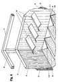
Fig. 4 zeigt einen perspektivischen Blick ins Innere des verschlossenen Behälters 3. Sichtbar sind dessen Wände und zwei der oberen Verbindungsstreben 6, (abgebrochen). Sichtbar sind auch die Stege 9, 10, zusammen mit den Stirnseiten der kurzen Stege 11.FIG. 4 shows a perspective view into the interior of the
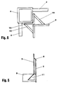
In Fig. 5 ist ein Detail-Querschnitt durch den Container gezeichnet, welcher die Stelle zeigt, wo der kurze Steg 11 am Behälter 3 angebracht ist.5 shows a detailed cross section through the container, which shows the location where the
Fig. 6 zeigt ein Ausführungsbeispiel der Führung 5. In der Ecke des Behälters 3 ist ein Stahlwinkel 15 angeschweisst, der an zwei Seiten der vertikalen Strebe 4 anliegt, jedoch nur so lange Schenkel hat, dass sie mit genügend Spiel an den Seitenblechen vorbeigleiten können. Versteift ist der Winkel 15 mittels eines Stützbleches 18, das beispielsweise über die ganze Länge des Winkels 15 verläuft. Jede Ecke des Behälters 3 ist in der beschriebenen Weise mit einer Führung 5 versehen.Fig. 6 shows an embodiment of the
Eine erste Variante hiezu enthält zwischen vertikaler Strebe 4 und Winkel 15 Gleitplatten aus Kunststoff eingefügt. Eine zweite Variante ist aus Fig. 7 ersichtlich.A first variant contains 15 plastic sliding plates inserted between
In Fig. 7 ist eine schematische Draufsicht auf eine Variante des erfindungsgemässen Containers gemäss Fig. 1-6 dargestellt. Anstatt nur vier vertikale Streben 4 weist er deren 6 auf; an den Längsseiten des Rahmens 1 befinden sich zwei weitere vertikale Streben 16. Die Führungen 5, welche für die vier Ecken in Fig. 6 beschrieben sind, werden für die Führungen 5 an den vertikalen Streben so modifiziert, dass anstelle eines Winkels 15 ein U-Profil 17 eingesetzt wird.FIG. 7 shows a schematic top view of a variant of the container according to the invention according to FIGS. 1-6. Instead of only four
Die in Fig. 7 gezeigte Variante kann selbstverständlich auf insgesamt acht oder mehr vertikale Streben 4, 16 erweitert werden.The variant shown in FIG. 7 can of course be expanded to a total of eight or more
Anstatt Führungen 5 mit Gleitflächen zu verwenden, ist es ebenso erfindungsgemäss, die Gleitflächen der Winkel 15 und der U-Profile 17 durch Rollen zu ersetzen, welche an den vertikalen Streben 4, abrollen.Instead of using
Der erfindungsgemässe, in den Fig. 1 bis 7 dargestellte Container kann prinzipiell in jeder gewünschten Grösse erzeugt werden. Modifikationen betreffen lediglich statische und nicht erfindungswesentliche Elemente. So ist selbstverständlich seine Ausgestaltung als ISO-Normcontainer für Bahn- und Schiffstransport vorgesehen. Die lediglich schematisch dargestellten Lasteinleitungsvorrichtungen 13 sind dann als den ISO-Normen entsprechende Vorrichtungen auszugestalten; die entsprechenden Vorrichtungen an den unteren vier Ecken sind ebenfalls entsprechend vorzusehen.The container according to the invention, shown in FIGS. 1 to 7, can in principle be produced in any desired size. Modifications only relate to static elements that are not essential to the invention. Of course, it is intended to be designed as an ISO standard container for rail and ship transport. The
Vorteile der Erfindung liegen unter anderem darin, dass der Container einfach und robust aufgebaut und kostengünstig herzustellen ist. Anstatt verschiedene Körnungen von Schüttgütern in teuren und oft wenig ausgelasteten Silos zu lagern, können diese in den erfindungsgemässen Containern gespeichert werden, was oft auch unnötige Umladevorgänge einspart. Ferner sind kapitalaufwendige Bahngossen einzusparen: Die Container werden von universell verwendbaren Container-Eisenbahnwagen abgeladen und auf eine verhältnismässig einfach zu gestaltende Entleerungsvorrichtung gehoben und entleert. Sollen die Container zunächst nicht entleert werden, so können sie - beispielsweise als ISO-Norm-Container - gestapelt werden. Der Transport-Zug wird damit sofort wieder frei und Silo-Kapazität wird nicht benötigt.Advantages of the invention include that the container is simple and robust and inexpensive to manufacture. Instead of storing different grain sizes of bulk goods in expensive and often underutilized silos, these can be stored in the containers according to the invention, which often also saves unnecessary reloading processes. Furthermore, capital-consuming railway gutters can be saved: the containers are unloaded from universally usable container railway wagons and lifted and emptied onto a relatively easy-to-design emptying device. If the containers are not to be emptied at first, they can be stacked, for example as an ISO standard container. The transport train is immediately free again and silo capacity is not required.
Ein weiterer Vorteil besteht darin, dass der Container - ausser dem Behälter 3 - keinerlei bewegliche Teile, keine Antriebe und keine Klappen aufweist. Damit entfällt die Notwendigkeit Teile zu bauen, zu finanzieren und zu warten, welche einerseits teuer sind, selten gebraucht werden und störungsanfällig sind; die notwendigen Investitionen können auf die Entleerungsstationen verlagert werden, womit der Kapitaleinsatz wesentlich verringert und die Wartung erleichtert wird.Another advantage is that the container - apart from the container 3 - has no moving parts, no drives and no flaps. This eliminates the need to build, finance and maintain parts that are expensive, rarely used and prone to failure; the necessary investments can be relocated to the emptying stations, which significantly reduces capital expenditure and simplifies maintenance.
Claims (10)
- A container for bulk materials, which has a bottom emptying facility, especially for bulk materials such as sand, gravel, coke, with a holder (3), which is drawn in at its lower portion in the shape of a truncated pyramid and has a number of roof-shaped webs (10), which run from one to the other of the long sides of the holder (3), are bonded to it in the region of the drawn in portion, and a component, which also has a number of roof-shaped webs (9) , which are so arranged that they run between the roof-shaped webs (10) of the holder (3), such that when the holder (3) is in its lowest possible position in relation to the component, the webs (9) of the component and the webs (10) of the holder (3) come together and the holder (3) is thereby closed, characterised in that- a basically square shaped framework (1) is present, with which the component is firmly joined at its lower part,- the holder (3) can move vertically inside the framework (1),- the framework (1) is constructed from vertical webs (4, 16) comprising square tubing, which are joined by welding at their upper ends to horizontal webs (20) and in their lower region to side plates (2),- the holder (3) is similarly built essentially in a rectangular shape, has at the least on its four vertical side edges a guide (5) on each, which can each move vertically on one of the vertical webs (4)- the holder (3) has further a number of roof-shaped connecting webs (6) in its upper region, which extend horizontally from one to the other long side of the holder and are bonded to them,- to two outside webs (10) of the holder (3) two plates (12) are welded extending vertically downwards and in the longitudinal direction of the holder (3), whose length corresponds at the most to the intervening space defined by the webs (9) of the framework (1), whereby it is effected that, when the container is set down on two transverse beams, whose length is at least the distance between two vertical plates (12) but at most the inside width of the framework (1), the framework (1) sinks over the holder (3) and the intervening spaces between the webs (9) on the framework (1), and the webs (10) on the holder (3) open for the bulk material.
- A container according to Claim 1, characterised in that- the upper rim of the holder (3) has a roof-shaped rail (7) welded around it,- a rail (8), inclined outwards and downwards is similarly fastened around the outside of the holder (3), which, in the closed state of the container, exactly covers the space between the wall of the holder (3) and the side plates (2) of the framework (1),- the lower edge of the holder (3), where it sits on the webs (9) of the framework (1) in the closed state, is strengthened in each position by a short piece of a similarly roof-shaped web (11), which extends from the drawn-in rim of the holder (3) towards the side plate (2).
- A container according to Claim 1, characterised in that the framework (1) has four vertical webs (4) and the holder (3) is equipped with four guides (5), which each abut two sides of the square tubing, which forms the vertical webs (4) of the framework (1), whereby the guides (5) are each stiffened by two support plates (18) on the holder (3)
- A container according to Claim 1, characterised in that- the framework (1) has at least six vertical webs (4, 16) formed from rectangular tubing, whereby four vertical webs (4) form the corners of the framework (1), the other vertical webs (16) are arranged on each of its long sides,- the guides (5) are each strengthened with two support plates (18) on the holder (3).
- A container according to Claim 3 or Claim 4, characterised in that- the guides (5) in the four corners of the holder are constructed as corners (15), which lie against the two side surfaces facing the holder of the rectangular tubes forming the vertical webs (4) so that they can slide and which extend in the horizontal direction so far that the guides (5) can move past the side plates (2),- the guides (15), which lie so that they can slide against the rectangular tubes forming the vertical webs (16), which vertical webs (16) are arranged between the webs (4) forming the corners of the framework (1), comprise U-profiles (17), which lie so that they can slide against the side surfaces of the aforementioned rectangular tubes facing the holder (3) and extend in the horizontal direction so far that the guides (5) can pass the side plates (2),
- A container according to Patent Claim 5, characterised in that the guides (5) glide directly along the vertical webs (4, 16).
- A container according to Patent Claim 5, characterised in that the guides (5) are provided with slide plates.
- A container according to Patent Claim 3 or 4, characterised in that- the guides (5) in the four corners of the holder (3) carry rollers, which can roll along the two side faces facing the holder of the rectangular tubes forming the vertical webs (4),- the guides (5), which attach to the webs (16), which are arranged between the corners of the framework (1), carry rollers, which can roll along the side faces facing the holder (3) and the adjacent faces of the rectangular tubes which form the vertical webs (16).
- A container according to Patent Claim 1, characterised in that the framework (1) has a load bearing attachment (13) at each of its eight corners.
- A container according to Patent Claim 9, characterised in that the load bearing attachments (13) comply with the standard specifications of the international Railways and Ship Transport.
Applications Claiming Priority (3)
| Application Number | Priority Date | Filing Date | Title |
|---|---|---|---|
| CH3033/93 | 1993-10-08 | ||
| CH303393 | 1993-10-08 | ||
| PCT/CH1993/000250 WO1995010466A1 (en) | 1993-10-08 | 1993-10-25 | Bulk material container with an emptying arrangement |
Publications (2)
| Publication Number | Publication Date |
|---|---|
| EP0672012A1 EP0672012A1 (en) | 1995-09-20 |
| EP0672012B1 true EP0672012B1 (en) | 1997-03-05 |
Family
ID=4247123
Family Applications (1)
| Application Number | Title | Priority Date | Filing Date |
|---|---|---|---|
| EP93922878A Expired - Lifetime EP0672012B1 (en) | 1993-10-08 | 1993-10-25 | Bulk material container with an emptying arrangement |
Country Status (7)
| Country | Link |
|---|---|
| US (1) | US5626253A (en) |
| EP (1) | EP0672012B1 (en) |
| AT (1) | ATE149462T1 (en) |
| CA (1) | CA2151278A1 (en) |
| DE (1) | DE59305666D1 (en) |
| ES (1) | ES2102065T3 (en) |
| WO (1) | WO1995010466A1 (en) |
Families Citing this family (4)
| Publication number | Priority date | Publication date | Assignee | Title |
|---|---|---|---|---|
| US6010022A (en) * | 1994-05-18 | 2000-01-04 | Buckhorn, Inc. | Dispensing box for flowable material |
| WO2003089202A1 (en) * | 2002-04-15 | 2003-10-30 | Boasso America Corporation (A Louisiana Corporation) | Method and apparatus for supplying bulk product to an end user |
| AT510892A1 (en) * | 2010-12-30 | 2012-07-15 | Schwer Johann | METHOD FOR REMOVING OIL OR OILY SUBSTANCES OF WATER SURFACES |
| BR102018074121A2 (en) * | 2018-11-23 | 2020-06-02 | Tmsa - Tecnologia Em Movimentação S.A. | RELIEF MODULE AND BULK MATERIAL DISCHARGE DEVICE |
Family Cites Families (14)
| Publication number | Priority date | Publication date | Assignee | Title |
|---|---|---|---|---|
| FR467082A (en) * | 1914-01-07 | 1914-06-03 | Dansk Svovlsyre | Movable bottom device or auxiliary bottom usable for emptying tanks, silos, reaction chambers for superphosphate, etc. |
| US2782011A (en) * | 1953-06-19 | 1957-02-19 | Sho Me Inc | Hoppers |
| LU38693A1 (en) * | 1959-06-22 | |||
| CH411684A (en) * | 1963-10-08 | 1966-04-15 | Pirelli | Container for the transport of liquids and incoherent materials, such as powders and granules |
| DE1949730B2 (en) * | 1969-10-02 | 1977-05-12 | CLOSURE FOR BULK GOODS CONTAINER | |
| US3863799A (en) * | 1973-06-20 | 1975-02-04 | Ppg Industries Inc | Adjustable bin for transporting articles |
| US4295431A (en) * | 1979-11-23 | 1981-10-20 | Aga Ab | Pallet for pressurized gas cylinders |
| US4410111A (en) * | 1980-10-24 | 1983-10-18 | Barger Lloyd D | Storage container for particulate material |
| US4662532A (en) * | 1985-11-04 | 1987-05-05 | Steel King Industries, Inc. | Foldable container |
| US5186351A (en) * | 1988-08-05 | 1993-02-16 | San Joaquin Valley Express | Slurry tank |
| JP2737000B2 (en) * | 1989-06-19 | 1998-04-08 | キヤノン株式会社 | Toner kit |
| BR8903115A (en) * | 1989-06-26 | 1991-01-02 | Cpm Do Brasil Ind E Comercio L | DEVICE TO CONTROL THE DISCHARGE OF MATERIAL FROM A STORAGE RESERVOIR |
| JPH0734827Y2 (en) * | 1990-07-09 | 1995-08-09 | セントラル硝子株式会社 | Glass plate pallet |
| NL9102109A (en) * | 1991-12-17 | 1993-07-16 | Zuidema Milieu Bv | DEVICE FOR COLLECTING WASTE, IN PARTICULAR WASTE PACKAGING GLASS. |
-
1993
- 1993-10-25 CA CA002151278A patent/CA2151278A1/en not_active Abandoned
- 1993-10-25 WO PCT/CH1993/000250 patent/WO1995010466A1/en active IP Right Grant
- 1993-10-25 US US08/464,843 patent/US5626253A/en not_active Expired - Fee Related
- 1993-10-25 AT AT93922878T patent/ATE149462T1/en not_active IP Right Cessation
- 1993-10-25 EP EP93922878A patent/EP0672012B1/en not_active Expired - Lifetime
- 1993-10-25 DE DE59305666T patent/DE59305666D1/en not_active Expired - Fee Related
- 1993-10-25 ES ES93922878T patent/ES2102065T3/en not_active Expired - Lifetime
Also Published As
| Publication number | Publication date |
|---|---|
| EP0672012A1 (en) | 1995-09-20 |
| CA2151278A1 (en) | 1995-04-20 |
| ES2102065T3 (en) | 1997-07-16 |
| US5626253A (en) | 1997-05-06 |
| WO1995010466A1 (en) | 1995-04-20 |
| DE59305666D1 (en) | 1997-04-10 |
| ATE149462T1 (en) | 1997-03-15 |
Similar Documents
| Publication | Publication Date | Title |
|---|---|---|
| AT506371B1 (en) | UNLOADING VEHICLE AND COMBINATION OF A UNLOADING VEHICLE WITH A CONTAINER COVER | |
| DE1992958U (en) | CONTAINER FOR TRANSPORTING REFRIGERATED GOODS. | |
| EP1135287B1 (en) | Low-platform railway car for glass stands | |
| EP0672012B1 (en) | Bulk material container with an emptying arrangement | |
| EP0444334B1 (en) | Mobile compost container | |
| DE102008015911B3 (en) | Arrangement for controlling and saving delivery of bulks from sorter in terminal container, has insert made of rectangular, filter opened at upper and lower end | |
| EP2830924B1 (en) | Transport container, vehicle, traction group, method for loading a transport container, and method for transporting bulk material | |
| DE102008031981A1 (en) | Transport vehicle for lifting and transporting ULDs and cargo pallets | |
| DE4110847C2 (en) | Stackable transport container for liquid and / or solid substances | |
| DE19501111A1 (en) | Transportation device for large=volume piece goods | |
| DE3816243A1 (en) | DOUBLE-WALLED FLOOR PANEL FOR LARGE CONTAINERS | |
| DE202009017605U1 (en) | Device for emptying flowable bulk materials | |
| DE1605012A1 (en) | Vehicle, especially a railroad car, with a hinged roof | |
| DE2159602C3 (en) | ||
| EP0513436B1 (en) | Waste collection container | |
| DE102006014213A1 (en) | Tilting mechanism for use in forklift truck, is connected to carrier of forklift truck through down-holding mandrel, and has tilting arm configured to tilt container placed on carrier of forklift truck | |
| EP0624499B1 (en) | Device on a wagon frame movable on rails for horizontal loading of containers | |
| DE2439172A1 (en) | PROCEDURE FOR FILLING A SILO SYSTEM AND EQUIPMENT FOR CARRYING OUT THIS PROCEDURE | |
| EP0677424B1 (en) | Transport vehicle for sheet material | |
| EP0646532B1 (en) | Storage and transport container | |
| EP3694792B1 (en) | Underground collection device for waste | |
| DE3790890C2 (en) | ||
| DE102007001747A1 (en) | Tilting attachment device for e.g. forklift truck, has tilting arm engaged to container, where device is provided around tilting axis parallel to transportation direction along rails for emptying bulk cargo from container | |
| DE202007003582U1 (en) | Tilting mechanism for use in forklift truck, is connected to carrier of forklift truck through down-holding mandrel, and has tilting arm configured to tilt container placed on carrier of forklift truck | |
| AT338107B (en) | COMBINATION OF A VEHICLE AND AT LEAST ONE CONTAINER FOR THE TRANSPORT OF AGRICULTURAL GOODS |
Legal Events
| Date | Code | Title | Description |
|---|---|---|---|
| PUAI | Public reference made under article 153(3) epc to a published international application that has entered the european phase |
Free format text: ORIGINAL CODE: 0009012 |
|
| 17P | Request for examination filed |
Effective date: 19950608 |
|
| AK | Designated contracting states |
Kind code of ref document: A1 Designated state(s): AT CH DE ES FR GB IT LI NL PT SE |
|
| 17Q | First examination report despatched |
Effective date: 19960219 |
|
| GRAG | Despatch of communication of intention to grant |
Free format text: ORIGINAL CODE: EPIDOS AGRA |
|
| GRAH | Despatch of communication of intention to grant a patent |
Free format text: ORIGINAL CODE: EPIDOS IGRA |
|
| GRAH | Despatch of communication of intention to grant a patent |
Free format text: ORIGINAL CODE: EPIDOS IGRA |
|
| GRAA | (expected) grant |
Free format text: ORIGINAL CODE: 0009210 |
|
| AK | Designated contracting states |
Kind code of ref document: B1 Designated state(s): AT CH DE ES FR GB IT LI NL PT SE |
|
| REF | Corresponds to: |
Ref document number: 149462 Country of ref document: AT Date of ref document: 19970315 Kind code of ref document: T |
|
| REG | Reference to a national code |
Ref country code: CH Ref legal event code: EP |
|
| REF | Corresponds to: |
Ref document number: 59305666 Country of ref document: DE Date of ref document: 19970410 |
|
| GBT | Gb: translation of ep patent filed (gb section 77(6)(a)/1977) |
Effective date: 19970501 |
|
| ITF | It: translation for a ep patent filed |
Owner name: KARAGHIOSOFF GIORGIO |
|
| ET | Fr: translation filed | ||
| REG | Reference to a national code |
Ref country code: CH Ref legal event code: NV Representative=s name: DR. REINHOLD C. SALGO PATENTANWALT |
|
| REG | Reference to a national code |
Ref country code: ES Ref legal event code: FG2A Ref document number: 2102065 Country of ref document: ES Kind code of ref document: T3 |
|
| PLBE | No opposition filed within time limit |
Free format text: ORIGINAL CODE: 0009261 |
|
| STAA | Information on the status of an ep patent application or granted ep patent |
Free format text: STATUS: NO OPPOSITION FILED WITHIN TIME LIMIT |
|
| 26N | No opposition filed | ||
| PGFP | Annual fee paid to national office [announced via postgrant information from national office to epo] |
Ref country code: PT Payment date: 20000912 Year of fee payment: 8 |
|
| PGFP | Annual fee paid to national office [announced via postgrant information from national office to epo] |
Ref country code: ES Payment date: 20000922 Year of fee payment: 8 |
|
| PGFP | Annual fee paid to national office [announced via postgrant information from national office to epo] |
Ref country code: SE Payment date: 20001017 Year of fee payment: 8 |
|
| PGFP | Annual fee paid to national office [announced via postgrant information from national office to epo] |
Ref country code: GB Payment date: 20001019 Year of fee payment: 8 |
|
| PGFP | Annual fee paid to national office [announced via postgrant information from national office to epo] |
Ref country code: FR Payment date: 20001027 Year of fee payment: 8 |
|
| PGFP | Annual fee paid to national office [announced via postgrant information from national office to epo] |
Ref country code: NL Payment date: 20001031 Year of fee payment: 8 Ref country code: AT Payment date: 20001031 Year of fee payment: 8 |
|
| PGFP | Annual fee paid to national office [announced via postgrant information from national office to epo] |
Ref country code: CH Payment date: 20001102 Year of fee payment: 8 |
|
| PGFP | Annual fee paid to national office [announced via postgrant information from national office to epo] |
Ref country code: DE Payment date: 20001219 Year of fee payment: 8 |
|
| PG25 | Lapsed in a contracting state [announced via postgrant information from national office to epo] |
Ref country code: GB Free format text: LAPSE BECAUSE OF NON-PAYMENT OF DUE FEES Effective date: 20011025 Ref country code: AT Free format text: LAPSE BECAUSE OF NON-PAYMENT OF DUE FEES Effective date: 20011025 |
|
| PG25 | Lapsed in a contracting state [announced via postgrant information from national office to epo] |
Ref country code: SE Free format text: LAPSE BECAUSE OF NON-PAYMENT OF DUE FEES Effective date: 20011026 Ref country code: ES Free format text: LAPSE BECAUSE OF NON-PAYMENT OF DUE FEES Effective date: 20011026 |
|
| PG25 | Lapsed in a contracting state [announced via postgrant information from national office to epo] |
Ref country code: LI Free format text: LAPSE BECAUSE OF NON-PAYMENT OF DUE FEES Effective date: 20011031 Ref country code: CH Free format text: LAPSE BECAUSE OF NON-PAYMENT OF DUE FEES Effective date: 20011031 |
|
| REG | Reference to a national code |
Ref country code: GB Ref legal event code: IF02 |
|
| PG25 | Lapsed in a contracting state [announced via postgrant information from national office to epo] |
Ref country code: PT Free format text: LAPSE BECAUSE OF NON-PAYMENT OF DUE FEES Effective date: 20020430 |
|
| PG25 | Lapsed in a contracting state [announced via postgrant information from national office to epo] |
Ref country code: NL Free format text: LAPSE BECAUSE OF NON-PAYMENT OF DUE FEES Effective date: 20020501 |
|
| EUG | Se: european patent has lapsed |
Ref document number: 93922878.9 |
|
| GBPC | Gb: european patent ceased through non-payment of renewal fee |
Effective date: 20011025 |
|
| REG | Reference to a national code |
Ref country code: CH Ref legal event code: PL |
|
| PG25 | Lapsed in a contracting state [announced via postgrant information from national office to epo] |
Ref country code: FR Free format text: LAPSE BECAUSE OF NON-PAYMENT OF DUE FEES Effective date: 20020628 |
|
| NLV4 | Nl: lapsed or anulled due to non-payment of the annual fee |
Effective date: 20020501 |
|
| PG25 | Lapsed in a contracting state [announced via postgrant information from national office to epo] |
Ref country code: DE Free format text: LAPSE BECAUSE OF NON-PAYMENT OF DUE FEES Effective date: 20020702 |
|
| REG | Reference to a national code |
Ref country code: FR Ref legal event code: ST |
|
| REG | Reference to a national code |
Ref country code: PT Ref legal event code: MM4A Free format text: LAPSE DUE TO NON-PAYMENT OF FEES Effective date: 20020430 |
|
| REG | Reference to a national code |
Ref country code: ES Ref legal event code: FD2A Effective date: 20021113 |
|
| PG25 | Lapsed in a contracting state [announced via postgrant information from national office to epo] |
Ref country code: IT Free format text: LAPSE BECAUSE OF NON-PAYMENT OF DUE FEES Effective date: 20051025 |