EP0671215B1 - Vorrichtung zum Einspannen eines Filtermittels in einer Zentrifugentrommel - Google Patents
Vorrichtung zum Einspannen eines Filtermittels in einer Zentrifugentrommel Download PDFInfo
- Publication number
- EP0671215B1 EP0671215B1 EP95101454A EP95101454A EP0671215B1 EP 0671215 B1 EP0671215 B1 EP 0671215B1 EP 95101454 A EP95101454 A EP 95101454A EP 95101454 A EP95101454 A EP 95101454A EP 0671215 B1 EP0671215 B1 EP 0671215B1
- Authority
- EP
- European Patent Office
- Prior art keywords
- clamping
- clamping ring
- drum
- constructed
- groove
- Prior art date
- Legal status (The legal status is an assumption and is not a legal conclusion. Google has not performed a legal analysis and makes no representation as to the accuracy of the status listed.)
- Expired - Lifetime
Links
Images

Classifications
-
- F—MECHANICAL ENGINEERING; LIGHTING; HEATING; WEAPONS; BLASTING
- F16—ENGINEERING ELEMENTS AND UNITS; GENERAL MEASURES FOR PRODUCING AND MAINTAINING EFFECTIVE FUNCTIONING OF MACHINES OR INSTALLATIONS; THERMAL INSULATION IN GENERAL
- F16B—DEVICES FOR FASTENING OR SECURING CONSTRUCTIONAL ELEMENTS OR MACHINE PARTS TOGETHER, e.g. NAILS, BOLTS, CIRCLIPS, CLAMPS, CLIPS OR WEDGES; JOINTS OR JOINTING
- F16B2/00—Friction-grip releasable fastenings
- F16B2/02—Clamps, i.e. with gripping action effected by positive means other than the inherent resistance to deformation of the material of the fastening
- F16B2/04—Clamps, i.e. with gripping action effected by positive means other than the inherent resistance to deformation of the material of the fastening internal, i.e. with spreading action
-
- B—PERFORMING OPERATIONS; TRANSPORTING
- B01—PHYSICAL OR CHEMICAL PROCESSES OR APPARATUS IN GENERAL
- B01D—SEPARATION
- B01D33/00—Filters with filtering elements which move during the filtering operation
- B01D33/06—Filters with filtering elements which move during the filtering operation with rotary cylindrical filtering surfaces, e.g. hollow drums
- B01D33/067—Construction of the filtering drums, e.g. mounting or sealing arrangements
-
- B—PERFORMING OPERATIONS; TRANSPORTING
- B01—PHYSICAL OR CHEMICAL PROCESSES OR APPARATUS IN GENERAL
- B01D—SEPARATION
- B01D33/00—Filters with filtering elements which move during the filtering operation
- B01D33/06—Filters with filtering elements which move during the filtering operation with rotary cylindrical filtering surfaces, e.g. hollow drums
- B01D33/11—Filters with filtering elements which move during the filtering operation with rotary cylindrical filtering surfaces, e.g. hollow drums arranged for outward flow filtration
-
- B—PERFORMING OPERATIONS; TRANSPORTING
- B04—CENTRIFUGAL APPARATUS OR MACHINES FOR CARRYING-OUT PHYSICAL OR CHEMICAL PROCESSES
- B04B—CENTRIFUGES
- B04B7/00—Elements of centrifuges
- B04B7/08—Rotary bowls
- B04B7/12—Inserts, e.g. armouring plates
- B04B7/16—Sieves or filters
-
- B—PERFORMING OPERATIONS; TRANSPORTING
- B04—CENTRIFUGAL APPARATUS OR MACHINES FOR CARRYING-OUT PHYSICAL OR CHEMICAL PROCESSES
- B04B—CENTRIFUGES
- B04B7/00—Elements of centrifuges
- B04B7/08—Rotary bowls
- B04B7/18—Rotary bowls formed or coated with sieving or filtering elements
Definitions
- the invention relates to a device for clamping a filter medium in a centrifuge drum a clamping ring, which is in the centrifuge drum by means of a Clamping device can be enlarged in its scope, so that the filter cloth between the tension ring and the inner one Shell surface of the centrifuge drum is clamped, according to the preamble of claim 1.
- Such a filter centrifuge e.g. a discontinuous Peeler centrifuge, includes one rotatable in a housing stored centrifuge drum, in which a filling element for the suspension to be filtered and a device for discharge the separated product layer protrudes. Within a filter medium is located in the centrifuge drum. A Filling element protrudes into and inside the centrifuge drum there is a device in the centrifuge drum to discharge the spun product.
- Discontinuous filter centrifuges are used to Solid-liquid mixtures (suspensions) discontinuously separate.
- the suspension is fed into the Centrifugal drum rotating at high speed. Due to the rotation of the drum, the suspension pressed against the drum shell, whereby the solid from the inserted filter medium is retained and the Liquid the filter cake that forms and the filter medium penetrates and through the filtrate holes from the Drum is thrown out.
- the liquid is up to a portion from the If the filter cake is spun off, the filter cake (product) discharged from the centrifuge by means of the discharge device. This is usually done by slow delivery a peeling knife into the rotating drum, whereby the filter cake removed by chips and out of the drum is carried out.
- the solid is separated from the suspension by means of the filter medium.
- the filter medium usually a Fabric made of metal or plastic threads is put into the drum inserted.
- the filter medium on the drum jacket just lies. Between filter medium and drum jacket there may be a drainage layer through which the Drain off the filtrate penetrating the filter medium the filtrate holes is facilitated.
- This drainage layer can be an advantage.
- it is not essential necessary and for pharmaceutical centrifuges where the Number of components in the process room can be kept low should be more of a disadvantage.
- the filter medium must be completely wrinkle-free in the drum. To do this ensure the filter media is different Execution of fasteners in the drum held.
- the filter medium is usually attached to the front and rear ends of the drum using a flexible Limb, e.g. a round cord made of plastic, rubber, or the like, or by means of a pack in one for it provided groove.
- a flexible Limb e.g. a round cord made of plastic, rubber, or the like
- This is the cord or the package driven into the groove using a wooden wedge (see Systematics in the construction of machines and apparatus for the chemical industry, special print from "construction" 1967/6, Dipl.-Ing. O. Knott, especially Fig. 4, 5, 6 and 7).
- This attachment of the filter medium is a primarily frictional connection, but related a positive characteristic on the force owns.
- the filter medium is in very high strength held the intended seat.
- the round cord / pack is made using hammer blows a wooden wedge is hammered into the groove provided.
- a wooden wedge is hammered into the groove provided.
- the Wooden wedge it can damage the filter medium come, whereby the filter medium is replaced immediately must become.
- the extremely long assembly time is this fastening method of approx. 4 to 6 hours per filter medium disadvantageous.
- the flat clamping rings do not require a complex drum geometry and can be used with all coated drums become.
- the assembly time for flat clamping rings is also relatively low.
- the invention has for its object to provide a device for clamping a filter medium in a centrifuge drum of the type mentioned, which is simple and quick to assemble with a simple construction and at the same time enables a particularly secure fixing of the filter medium in the centrifuge drum.
- the tensioning device should be designed so that without corresponding precautions on the clearing device of the Centrifuge the solid except for a residual layer of approximately 4 mm can be removed from the centrifuge.
- the invention makes use of the knowledge that the Centrifugal force advantageous for clamping a clamping ring can be exploited.
- the device according to the invention enables a clamping ring at the front and rear ends of the drum respectively inserted the drum and there its corresponding End sections are engaged with each other. Then there is a corresponding pre-tensioning of the clamping ring, whereby the clamping ring can be arranged in a groove, which, however, depending on the elasticity of the filter medium, not necessarily is necessary because of the self-tensioning characteristic of the clamping ring and the local compression of the Filter medium when accelerating the centrifuge drum Groove and thus a positive connection is created.
- end portions of the clamping ring on each other facing surfaces can be brought into engagement with one another, in one direction movable against the other and in the opposite direction self-locking locking profiles exhibit.
- Such self-locking locking profiles in one direction are simple and cheap to manufacture and allow easy assembly and disassembly in the centrifuge drum.
- Such locking profiles are advantageously as sawtooth profiles educated.
- a further advantageous embodiment of the invention provides before that the flank angle of the teeth of the sawtooth profile in Clamping direction of the clamping ring less than in the opposite Direction is.
- the flank angle in the clamping direction about 15 ° to 35 ° and in the opposite Direction about 90 ° to 105 °. This will on the one hand, the tension effect due to end sections sliding apart when starting up the centrifuge drum and on the other hand a secure locking of the end sections against each other enables.
- the mutually facing surfaces the radial inside of one end section and on the formed radially outside of the other end portion are, which are engaged with each other End sections about the same height as the rest of the clamping ring exhibit.
- the invention provided that an end portion of the Clamping ring as a groove and the other end section of the Tension ring as an elastic, engaging with the groove bringable fork is formed.
- the groove and the Fork formed in the axial direction of the clamping ring, and the mutually facing surfaces are on the inside the groove or the outer sides of the fork.
- the clamping force that the clamping ring according to the invention on Can apply filter media is much larger than this can usually be done through human power. Replenishing the filter medium in the centrifugal field, too when the drum is filled, it is automatically re-tensioned the ring by jumping the clasp in the next catch is reached.
- the design of the clamping ring is especially for pharmaceutical Suitable for industry because there are no moving elements or retractable joints are required for the clamping ring.
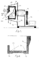
- the discontinuous filter centrifuge shown in Fig. 1 has a stationary machine frame 10 on which a centrifuge shaft 12 is rotatably mounted, and on the there is a coupling system 14 at one end via which the shaft 12 can be rotated. At the other At the end of the shaft 12 there is a centrifuge drum 16 from a drum shell 18, a drum base 20 and one Bordring 22, attached. The centrifuge drum 16 can bore to remove filtrate. Within the Centrifuge drum 16 is a filter medium 24. In the centrifuge drum 16 projects into a filling element 26. Furthermore is located within the centrifuge drum 16 Device 28 for discharging the thrown product.
- the filter means 24 is by means of a clamping ring 30 set in grooves 32. If it is is an elastic filter means 24, the grooves 32nd possibly omitted, since the clamping ring 30, as already mentioned, due to the centrifugal force in the filter medium 24 presses in.
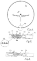
- the clamping ring 30 is curved in a circle and consists of a one-piece flat material. At its flattened end sections 34, 36 is the clamping ring 30 with a clamping device 38 in the form of a one-way self-locking Ratchet device provided. That is, each other opposite surfaces 40, 42 have a self-locking Snap profile on that in the illustrated embodiment is designed as a sawtooth profile 44.
- the Sawtooth profile 44 is on the radial inside and the formed radially outside of the end portions 34, 36.
- the flank angle of the individual teeth (see Fig. 5) of the sawtooth profile 44 in the clamping direction of the clamping ring 30 less than in the opposite direction.
- the flank angle in the clamping direction is approximately 15 ° to 35 ° and in the opposite direction about 90 ° to 105 °.
- Fig. 4 is the initial engagement of the end portions 34, 36 in the untensioned or minimally pre-stressed state, i.e. in the idle state of the centrifuge drum 16.
- Fig. 5 shows the clamping device 38 of the clamping ring 30 in tensioned state after the centrifuge drum 16 its Has reached final speed.
- the tensioner 38 expands, i.e. the two End sections 34, 36 of the clamping ring 30 slide on the sawtooth profile 44 and are against a relaxation movement locked.
- the clamping ring 30 itself corresponds essentially the first embodiment, i.e. he consists of a flat material, e.g. a flat steel. It however, are also different in both embodiments Profiles, e.g. Hollow profiles, spherical profiles etc., possible.
- This embodiment differs from the first embodiment in the formation of the clamping device 38.
- the one end section 34 of the clamping ring 30 as a groove 46 and the other end section 36 of the clamping ring 30 as an elastic, engageable with the groove 46 Fork 48 trained.
- the groove 46 and the fork 48 are in Axial direction of the clamping ring 30 formed and point to the mutually facing surfaces 40, 42, i.e. on the inside the groove 46 and the outer sides of the fork 48, a sawtooth profile 44 on. In this case it is a so-called "Multi-tooth lock". It is also possible only a pair of facing surfaces 40, 42 with the in To be engaged sawtooth profile 44 if so sufficient stability is guaranteed.
- the clamping ring 30 is placed in the centrifuge drum 16, and in the loose state, the one end portion 36 in the inserted other end portion 34 of the clamping device 38.
- the clamping ring 30 is initially fixed for generation a certain minimal preload by hand and then when starting up the centrifuge drum 16 by means of the Centrifugal force.
- With regard to the formation of the sawtooth profile 44 corresponds to the second embodiment of the tensioning device 38 of the first embodiment.
Landscapes
- Chemical & Material Sciences (AREA)
- Chemical Kinetics & Catalysis (AREA)
- Engineering & Computer Science (AREA)
- General Engineering & Computer Science (AREA)
- Mechanical Engineering (AREA)
- Centrifugal Separators (AREA)
Description
- Fig. 1
- eine schematische Ansicht einer Filterzentrifuge;
- Fig. 2
- eine vergrößerte Schnittansicht der Filterzentrifuge gemäß Fig. 1 längs der Linie II-II;
- Fig. 3
- eine Ansicht einer ersten Ausführungsform des Spannrings;
- Fig. 4
- eine vergrößerte Teilansicht des Spannrings gemäß Fig. 3 im entspannten Zustand;
- Fig. 5
- eine vergrößerte Teilansicht des Spannrings gemäß Fig. 3 im gespannten Zustand mit einer Detailansicht des Sägezahnprofils;
- Fig. 6
- eine Ansicht einer zweiten Ausführungsform des Spannrings;
- Fig. 7
- eine vergrößerte Teilansicht des Spannrings gemäß Fig. 6 mit einer vergrößerten Darstellung des Sägezahnprofils im entspannten Zustand; und
- Fig. 8
- eine vergrößerte Teilansicht des Spannrings gemäß Fig. 6 im gespannten Zustand.
Claims (10)
- Vorrichtung zum Einspannen eines Filtermittels (24) in einer Zentrifugentrommel (16) mit einem Spannring (30), der in der Zentrifugentrommel (16) mittels einer Spanneinrichtung (38) in seinem Umfang vergrößerbar ist, so daß das Filtertuch zwischen dem Spannring (30) und der inneren Mantelfläche der Zentrifugentrommel (16) eingespannt ist, dadurch gekennzeichnet, daß die Spanneinrichtung (38) als eine Ratschen-Einrichtung ausgebildet ist.
- Vorrichtung nach Anspruch 1, dadurch gekennzeichnet, daß Endabschnitte (34, 36) des Spannrings (30) an einander zugewandten Flächen (40, 42) miteinander in Eingriff bringbare, in der einen Richtung gegeneinander bewegbare und in der entgegengesetzten Richtung selbsthemmende Rast-Profile aufweisen.
- Vorrichtung nach Anspruch 1 oder 2 , dadurch gekennzeichnet, daß die Rast-Profile als Sägezahnprofile (44) ausgebildet sind.
- Vorrichtung nach einem der Ansprüche 1 bis 3, dadurch gekennzeichnet, daß der Flankenwinkel der einzelnen Zähne des Sägezahnprofils (44) in Spannrichtung des Spannrings (30) geringer als in entgegengesetzter Richtung ist.
- Vorrichtung nach einem der Ansprüche 1 bis 4, dadurch gekennzeichnet, daß der Flankenwinkel in Spannrichtung etwa 15° bis 35° und in entgegengesetzter Richtung etwa 90° bis 105° beträgt.
- Vorrichtung nach einem der Ansprüche 1 bis 5, dadurch gekennzeichnet, daß die einander zugewandten Flächen (40, 42) an der radialen Innenseite des einen Endabschnitts (36) und an der radialen Außenseite des anderen Endabschnitts (34, 36) ausgebildet sind.
- Vorrichtung nach Anspruch 6, dadurch gekennzeichnet, daß die miteinander in Eingriff gebrachten Endabschnitte (34, 36) etwa die gleiche Höhe wie der übrige Spannring (30) aufweisen.
- Vorrichtung nach einem der Ansprüche 1 bis 5, dadurch gekennzeichnet, daß ein Endabschnitt (34) des Spannrings (30) als Nut (46) und der andere Endabschnitt (36) des Spannrings (30) als eine elastische, mit der Nut (46) in Eingriff bringbare Gabel (48) ausgebildet ist.
- Vorrichtung nach Anspruch 8, dadurch gekennzeichnet, daß die Nut (46) und die Gabel (48) in Achsrichtung des Spannrings (30) ausgebildet sind und die einander zugewandten Flächen (40, 42) jeweils an den Innenseiten der Nut (46) und den Außenseiten der Gabel (48) angeordnet sind.
- Vorrichtung nach einem der Ansprüche 1 bis 9, dadurch gekennzeichnet, daß der Spannring (30) aus einem Flachmaterial besteht.
Applications Claiming Priority (2)
| Application Number | Priority Date | Filing Date | Title |
|---|---|---|---|
| DE4407515A DE4407515C1 (de) | 1994-03-07 | 1994-03-07 | Vorrichtung zum Einspannen eines Filtermittels in einer Zentrifugentrommel |
| DE4407515 | 1994-03-07 |
Publications (2)
| Publication Number | Publication Date |
|---|---|
| EP0671215A1 EP0671215A1 (de) | 1995-09-13 |
| EP0671215B1 true EP0671215B1 (de) | 1999-05-06 |
Family
ID=6512050
Family Applications (1)
| Application Number | Title | Priority Date | Filing Date |
|---|---|---|---|
| EP95101454A Expired - Lifetime EP0671215B1 (de) | 1994-03-07 | 1995-02-03 | Vorrichtung zum Einspannen eines Filtermittels in einer Zentrifugentrommel |
Country Status (2)
| Country | Link |
|---|---|
| EP (1) | EP0671215B1 (de) |
| DE (2) | DE4407515C1 (de) |
Families Citing this family (8)
| Publication number | Priority date | Publication date | Assignee | Title |
|---|---|---|---|---|
| CA2263955A1 (en) * | 1996-08-05 | 1998-02-12 | Norbertus Verduijn | Method and apparatus for filtering a fluid |
| LU90307B1 (de) * | 1998-10-28 | 2000-05-02 | Wurth Paul Sa | Vorrichtung zum Entwaessern granulierter Materialien |
| GB2407525A (en) * | 2003-10-30 | 2005-05-04 | Kenwood Marks Ltd | Juicer arrangement |
| FR2890320B1 (fr) * | 2005-09-05 | 2007-11-23 | Lionel Birken | Toile d'essorage |
| EP1787723B1 (de) * | 2005-11-18 | 2017-02-22 | Ferrum AG | Zentrifugenkartusche |
| EP1935499A1 (de) * | 2006-12-21 | 2008-06-25 | Ferrum AG | Zentrifugentrommel |
| FR3023729B1 (fr) * | 2014-07-18 | 2021-02-12 | Perrier Sorem | Element filtrant ainsi qu'un tambour filtrant equipe dudit element |
| DE102014119605A1 (de) * | 2014-12-23 | 2016-06-23 | Andritz Kmpt Gmbh | Filterzentrifuge |
Family Cites Families (4)
| Publication number | Priority date | Publication date | Assignee | Title |
|---|---|---|---|---|
| US3283909A (en) * | 1963-12-20 | 1966-11-08 | Ametek Inc | Centrifugal separator |
| FR2293858A7 (fr) * | 1974-12-04 | 1976-07-02 | Spanberg B | Bague de serrage pour coincer une matiere contre la paroi interieure d'une ouverture |
| DE2938684A1 (de) * | 1979-09-25 | 1981-04-09 | Krauss-Maffei AG, 8000 München | Vorrichtung zum einspannen von filtertuechern in zentrifugentrommeln |
| DE3916383C2 (de) * | 1989-05-19 | 1999-01-07 | Guntram Krettek | Vorrichtung zum Halten von Filterfolien oder Filtertüchern |
-
1994
- 1994-03-07 DE DE4407515A patent/DE4407515C1/de not_active Expired - Fee Related
-
1995
- 1995-02-03 DE DE59505809T patent/DE59505809D1/de not_active Expired - Lifetime
- 1995-02-03 EP EP95101454A patent/EP0671215B1/de not_active Expired - Lifetime
Also Published As
| Publication number | Publication date |
|---|---|
| DE4407515C1 (de) | 1995-08-17 |
| DE59505809D1 (de) | 1999-06-10 |
| EP0671215A1 (de) | 1995-09-13 |
Similar Documents
| Publication | Publication Date | Title |
|---|---|---|
| EP0509322B1 (de) | Verbindungseinrichtung zum verstellbaren Verbinden eines ersten mit einem zweiten Konstruktionselement, insbesondere von Rohren oder Stäben für eine Fixationsvorrichtung | |
| EP2422002B1 (de) | Kreiskamm | |
| CH671420A5 (de) | ||
| DE68918916T2 (de) | Kompressionsgerät für die Anastomose von hohlen Organen. | |
| DE4407515C1 (de) | Vorrichtung zum Einspannen eines Filtermittels in einer Zentrifugentrommel | |
| EP0844082A2 (de) | Spannvorrichtung in einer Rotationsdruckmaschine | |
| DE2830494A1 (de) | Kurbel fuer ein fahrrad o.dgl. | |
| EP1476066A1 (de) | Selbstauswringbarer mopp | |
| DE8814135U1 (de) | Ackerwalze | |
| EP0990063B1 (de) | Wälzgelagerte druckrolle für textilmaschinen, insbesondere für texturiermaschinen | |
| DE3205161A1 (de) | Vorrichtung zum befestigen eines filterteiles in einer zentrifuge | |
| DE602005005644T2 (de) | Auswechselbare Stollenstruktur für Sportschuhe | |
| WO1985005413A1 (fr) | Dispositif de surete de vis en particulier pour accouplements d'arbres | |
| DE3814412A1 (de) | Deckelstab fuer karden | |
| EP0849080B1 (de) | Kanalabdeckung bei einem Druckzylinder einer Offsetdruckmaschine | |
| WO2020165305A1 (de) | Orthese zur statischen dehnung der wadenmuskulatur | |
| DE202010008227U1 (de) | Filtrationstrommel eines Mikrosiebfilters und Filtrationsmittel dafür | |
| DE4113572B4 (de) | Schleifstein | |
| DE4321384C1 (de) | Schlammentwässerungspresse mit einer Schlammaufnahmekammer und darin angeordneten Trennsträngen | |
| DE3909936A1 (de) | Verfahren und vorrichtung zum herstellen eines undurchlaessigen und biegsamen bandes oder schlauches | |
| DE9201516U1 (de) | Filterpatrone | |
| DE10024722C2 (de) | Membranfilterplatte für eine Filterpresse sowie Trägerplatte und Membran für eine solche Membranfilterplatte | |
| EP0335120A2 (de) | Zentrifugalapparat | |
| EP1264627A1 (de) | Filtertuch für eine Filtrationsvorrichtung und Verfahren zur Montage eines Filtertuchs | |
| DE4442300A1 (de) | Betätigungseinrichtung für eine Spannvorrichtung für Druckplatten in Rotationsdruckmaschinen |
Legal Events
| Date | Code | Title | Description |
|---|---|---|---|
| PUAI | Public reference made under article 153(3) epc to a published international application that has entered the european phase |
Free format text: ORIGINAL CODE: 0009012 |
|
| AK | Designated contracting states |
Kind code of ref document: A1 Designated state(s): CH DE GB IE IT LI |
|
| 17P | Request for examination filed |
Effective date: 19960307 |
|
| GRAG | Despatch of communication of intention to grant |
Free format text: ORIGINAL CODE: EPIDOS AGRA |
|
| GRAG | Despatch of communication of intention to grant |
Free format text: ORIGINAL CODE: EPIDOS AGRA |
|
| GRAH | Despatch of communication of intention to grant a patent |
Free format text: ORIGINAL CODE: EPIDOS IGRA |
|
| 17Q | First examination report despatched |
Effective date: 19981009 |
|
| GRAH | Despatch of communication of intention to grant a patent |
Free format text: ORIGINAL CODE: EPIDOS IGRA |
|
| GRAA | (expected) grant |
Free format text: ORIGINAL CODE: 0009210 |
|
| AK | Designated contracting states |
Kind code of ref document: B1 Designated state(s): CH DE GB IE IT LI |
|
| REG | Reference to a national code |
Ref country code: CH Ref legal event code: EP |
|
| GBT | Gb: translation of ep patent filed (gb section 77(6)(a)/1977) |
Effective date: 19990507 |
|
| REF | Corresponds to: |
Ref document number: 59505809 Country of ref document: DE Date of ref document: 19990610 |
|
| REG | Reference to a national code |
Ref country code: CH Ref legal event code: NV Representative=s name: KIRKER & CIE SA |
|
| REG | Reference to a national code |
Ref country code: IE Ref legal event code: FG4D Free format text: GERMAN |
|
| REG | Reference to a national code |
Ref country code: CH Ref legal event code: PUE Owner name: KRAUSS-MAFFEI AKTIENGESELLSCHAFT TRANSFER- MANNESM |
|
| REG | Reference to a national code |
Ref country code: GB Ref legal event code: 732E |
|
| PLBE | No opposition filed within time limit |
Free format text: ORIGINAL CODE: 0009261 |
|
| STAA | Information on the status of an ep patent application or granted ep patent |
Free format text: STATUS: NO OPPOSITION FILED WITHIN TIME LIMIT |
|
| 26N | No opposition filed | ||
| REG | Reference to a national code |
Ref country code: GB Ref legal event code: IF02 |
|
| REG | Reference to a national code |
Ref country code: GB Ref legal event code: 732E |
|
| REG | Reference to a national code |
Ref country code: CH Ref legal event code: PUE Owner name: MANNESMANN DEMAG KRAUSS-MAFFEI AG TRANSFER- KRAUSS |
|
| PGFP | Annual fee paid to national office [announced via postgrant information from national office to epo] |
Ref country code: IE Payment date: 20110216 Year of fee payment: 17 |
|
| REG | Reference to a national code |
Ref country code: IE Ref legal event code: MM4A |
|
| PG25 | Lapsed in a contracting state [announced via postgrant information from national office to epo] |
Ref country code: IE Free format text: LAPSE BECAUSE OF NON-PAYMENT OF DUE FEES Effective date: 20120203 |
|
| PGFP | Annual fee paid to national office [announced via postgrant information from national office to epo] |
Ref country code: CH Payment date: 20140220 Year of fee payment: 20 |
|
| PGFP | Annual fee paid to national office [announced via postgrant information from national office to epo] |
Ref country code: IT Payment date: 20140224 Year of fee payment: 20 |
|
| PGFP | Annual fee paid to national office [announced via postgrant information from national office to epo] |
Ref country code: GB Payment date: 20140220 Year of fee payment: 20 |
|
| PGFP | Annual fee paid to national office [announced via postgrant information from national office to epo] |
Ref country code: DE Payment date: 20140417 Year of fee payment: 20 |
|
| REG | Reference to a national code |
Ref country code: DE Ref legal event code: R071 Ref document number: 59505809 Country of ref document: DE |
|
| REG | Reference to a national code |
Ref country code: CH Ref legal event code: PL |
|
| REG | Reference to a national code |
Ref country code: GB Ref legal event code: PE20 Expiry date: 20150202 |
|
| PG25 | Lapsed in a contracting state [announced via postgrant information from national office to epo] |
Ref country code: GB Free format text: LAPSE BECAUSE OF EXPIRATION OF PROTECTION Effective date: 20150202 |