EP0668418B1 - Scaffold - Google Patents
Scaffold Download PDFInfo
- Publication number
- EP0668418B1 EP0668418B1 EP95100037A EP95100037A EP0668418B1 EP 0668418 B1 EP0668418 B1 EP 0668418B1 EP 95100037 A EP95100037 A EP 95100037A EP 95100037 A EP95100037 A EP 95100037A EP 0668418 B1 EP0668418 B1 EP 0668418B1
- Authority
- EP
- European Patent Office
- Prior art keywords
- staging
- support
- folded
- floor
- stage
- Prior art date
- Legal status (The legal status is an assumption and is not a legal conclusion. Google has not performed a legal analysis and makes no representation as to the accuracy of the status listed.)
- Expired - Lifetime
Links
Images
Classifications
-
- E—FIXED CONSTRUCTIONS
- E04—BUILDING
- E04G—SCAFFOLDING; FORMS; SHUTTERING; BUILDING IMPLEMENTS OR AIDS, OR THEIR USE; HANDLING BUILDING MATERIALS ON THE SITE; REPAIRING, BREAKING-UP OR OTHER WORK ON EXISTING BUILDINGS
- E04G1/00—Scaffolds primarily resting on the ground
- E04G1/34—Scaffold constructions able to be folded in prismatic or flat parts or able to be turned down
-
- E—FIXED CONSTRUCTIONS
- E04—BUILDING
- E04G—SCAFFOLDING; FORMS; SHUTTERING; BUILDING IMPLEMENTS OR AIDS, OR THEIR USE; HANDLING BUILDING MATERIALS ON THE SITE; REPAIRING, BREAKING-UP OR OTHER WORK ON EXISTING BUILDINGS
- E04G17/00—Connecting or other auxiliary members for forms, falsework structures, or shutterings
- E04G17/002—Workplatforms, railings; Arrangements for pouring concrete, attached to the form
-
- E—FIXED CONSTRUCTIONS
- E04—BUILDING
- E04G—SCAFFOLDING; FORMS; SHUTTERING; BUILDING IMPLEMENTS OR AIDS, OR THEIR USE; HANDLING BUILDING MATERIALS ON THE SITE; REPAIRING, BREAKING-UP OR OTHER WORK ON EXISTING BUILDINGS
- E04G5/00—Component parts or accessories for scaffolds
- E04G5/06—Consoles; Brackets
- E04G5/061—Consoles; Brackets specially adapted for attachment to scaffolds
-
- E—FIXED CONSTRUCTIONS
- E04—BUILDING
- E04G—SCAFFOLDING; FORMS; SHUTTERING; BUILDING IMPLEMENTS OR AIDS, OR THEIR USE; HANDLING BUILDING MATERIALS ON THE SITE; REPAIRING, BREAKING-UP OR OTHER WORK ON EXISTING BUILDINGS
- E04G5/00—Component parts or accessories for scaffolds
- E04G5/06—Consoles; Brackets
- E04G5/062—Consoles; Brackets specially adapted for attachment to building walls
Definitions
- the invention relates to a work platform for a scaffold, in particular for a scaffold in concrete formwork with supports that can be folded up onto the underside of the floor covering of the stage.
- the supports supporting the stage floor are supported on the latter by hanging them in devices arranged on the building wall. It is known, for example FR-A-2 676 771, to fold the supports for stacking onto the underside of the stage floor covering. In known stages, however, a sufficiently flat lower surface of the folded stage is only obtained when the supports are so short that they do not overlap when folded up on the stage floor. However, this cannot always be achieved with a reasonable length of the stage section, especially not if a preferably removable sub-stage is provided below the main stage on the scaffold supports. Also the safety regulations for such work platforms often do not allow the length of the supports to be limited to the size which is approximately half the length of the platform, so that the supports can be folded under the platform without overlapping.
- the invention has for its object to provide a working platform that has a folded flat surface when folded, but the supports have a length that ensures the safety of the working platform in any case.
- the pivot axis of at least one support is movable at right angles to the floor surface of the stage.
- the pivot axis of the support can be moved into a position in which, when the supports overlap when the stage is folded, each support lies in such a way that its lower surface runs parallel to the stage floor.
- the folded stage has a flat lower surface, so that many of these stages can be stacked one above the other for storage or transport without the load capacity of the stage or its safety being reduced in the working state.
- the guides in which the pivot axis is movably guided, can, for example, allow the support to be removed from the stage covering, for example if these guides are a closable slot which is open at the bottom.
- the distance of the pivot axis of the support from the stage floor can only be changed by the amount that an overlying support assumes in the position folded toward the underside of the floor covering.
- the pivot axis of a support is held to be displaceable at right angles to the floor surface of the stage by the thickness of a support.
- This displacement of the pivot axis of a support can, as already mentioned, take place in that the part which forms the axis of rotation of the support is guided in a slot which is formed by at least one fitting.
- the device for the axis of rotation of a support which is carried out at right angles to the floor covering, is realized in that the axis of rotation is rotatably mounted at the free end of a pivotally mounted lever.
- a flat lower surface of a collapsed work platform that runs parallel to the stage floor is not only useful when stacking, but also when transporting, for example when the collapsed platform is to be transported with a forklift so that the folded supports are on the fork of the forklift.
- the stage has a foot with which an upper stage is supported on the next lower stage when stacking several superimposed, folded stages.
- a foot with which an upper stage is supported on the next lower stage when stacking several superimposed, folded stages.
- Such feet can be attached to the underside of the floor covering, but can also be formed by a fitting, for example, which limits the slot for the displacement of the axis of rotation of the support.
- the feet can be so long in embodiments of the invention that between two superimposed, folded stages, a space remains in which to transport the stage Fork of a forklift can be retracted.
- a carrier can be arranged on the sides of the work platform, at least on its narrow side, the width of which projects below the lower surface of the stage floor by the amount that two folded supports take up.
- the lower edge of this transverse beam can then form the support of a collapsed platform on the fork of a forklift truck, whereby, if feet are provided in these embodiments, these feet in turn protrude further down by the amount required to be on the floor or to easily insert the fork of a forklift to a next folded stage.
- the displaceability of the pivot axis of a support can be realized by an elongated hole in a fitting attached to the underside of the stage covering.
- the fitting for limiting the slot has a rod which at the same time forms the pivot bearing for a hook which is mounted in the fitting about an axis which is vertical in the working position of the platform. In a swiveled position, this hook serves as a support for the lower of the supports folded up on the stage floor.
- the foldable stage section has a stage floor 1 which is supported on two supports 2 and 3, which have an approximately triangular shape in the embodiment shown.
- the parallel to the wall plane, with the stage vertical 4 of each support has near its upper end a hook 5 or 5 'and about halfway up a hook 6 or 6' with which they are hung in appropriate loops or shoes can be attached to the wall of the building and through which the load of the stage is transferred to the building wall.
- At the lower end of the vertical rod 4 there is also a device 7 or 7 'for support on the wall.
- an oblique rod 8 or 8 ' extends upwards outward, where it is fastened at 9 or 9' to a cross rod 10 or 24 and beyond the fastening point 9 or 9 'a projection 11 or . 11 '.
- the cross bar 10 with the vertical bar 4 is fastened at 9 or 9' to a cross rod 10 or 24 and beyond the fastening point 9 or 9 'a projection 11 or . 11 '.
- Stiffening rods 12 and 13 are also used to stiffen the support 3, which in the illustrated embodiment also has the shape of a bracket like the support 2.
- Devices are also provided on the stage floor in which a railing, designated as a whole, can be attached.
- the storage of the supports 2 and 3 is described at one end of the stage in connection with the support 2. At the other end of the stage there is a mirror-image arrangement for mounting the support 3.
- the crossbar 10 forms the axis of rotation about which the console 2 can be pivoted toward the underside of the stage floor 1 when the stage is removed.
- a fitting 15 is used, which is shown on a larger scale in FIG. 2 and which is provided at both ends of the crossbar 10, that is to say on the inside of the stage facing the building wall and on the outside of the stage facing away from the building wall.
- the fitting 15 has a plate 16 which extends downward from the edge of the stage floor 1 and at the same time forms a foot 28 for supporting the folded stage.
- the plate 16 has on its inwardly directed edge 17 a support 18 for the cross bar 10.
- a rod 19 is fastened, which together with the edge 17 delimits a slot 20 in which the crossbar 10 can move at right angles to the level of the stage floor 1 and thus change its distance from the lower surface of the stage floor.
- a pivot lock 21 is pivotally mounted around the rod 19 and has a bearing surface 22.
- the cross bar 10 In the working position, ie when it is suspended on the building wall and attached stage, the cross bar 10 is located at the upper end of the slot 20 and in the embodiment shown supports the stage floor 1 directly. However, this can also be done using appropriate intermediate pieces. If the stage is suspended, the weight of the supports moves the crossbar to the lower end of slot 20. The supports 2 and 3 are then folded in.
- the pivot axis 24 of the support 3 is supported, as mentioned, on a fitting which is arranged at the end of the stage floor 1 which faces away from the end of the stage floor which is shown in FIG. 2. If the support 3 is pivoted clockwise about its pivot axis 24 to rest on the stage floor 1, the fuse 21 is first pivoted so far about the axis of the rod 19 that the lower end 7 'of the support 3 can be pivoted past the pivot lock 21 . The swivel lock 21 is then swiveled back into the path of the lower end of the support 3 and this lower end is placed on the bearing surface 22.
- the cross bar 24, which forms the pivot axis of the support 3 is still at the lower end of the slot 20 of the fitting arranged there.
- the support 2 is pivoted counterclockwise around the crossbar 10 to the underside of the stage floor 1 and the lower end of the support 2 is placed on the swivel lock 25, which is arranged on a fitting 23, which is arranged on the opposite end of the fitting 16 of the stage is.
- the support comes to rest on the already pivoted-in support 3 and presses this support upward, so that its crossbar 24 moves into the upper end of the slot there. Since the end 7 of the support 2 on the swivel lock 25 and the crossbar 10 rests at the lower end of the slot 20, the support 2 runs flat and parallel to the stage floor 1.
- each side end of the stage there is also a cross member 26 fastened to the narrow side of the stage floor, the leg 27 of which protrudes somewhat further down than the dimension required by the two supports 2 and 3 which are folded over one another.
- the leg 27 therefore extends a little further below the stage floor 1 than the support 18, which is provided at the lower end of the slot.
- this lower edge 29 then rests on the forklift, the fork of which can also rest on the cross tube 10, provided that at this end of the stage the cross bar 10 is in the lower position in the slot 20.
- the fittings 16 and the corresponding devices such as the swivel lock can be arranged at all four corners of the stage floor 1 in embodiments of the invention.
- the folded stage points to everyone Corner one foot
- the two swivel locks on the outer edge have no function, but they can be useful when other than triangular brackets are used as supports, e.g. rectangular frames.
- the fitting 16 can be designed so that the supports are removably attached to it, preferably in a form-fitting manner without the use of screws.
- the invention can be implemented both on entire stages and on individual stage sections.
Description
Die Erfindung bezieht sich auf eine Arbeitsbühne für ein Gerüst, insbesondere für ein Gerüst bei Betonschalungen mit an die Unterseite des Bodenbelages der Bühne heranklappbaren Stützen.The invention relates to a work platform for a scaffold, in particular for a scaffold in concrete formwork with supports that can be folded up onto the underside of the floor covering of the stage.
Bei bekannten Bühnen dieser Art werden die den Bühnenboden tragenden Stützen durch Einhängen in an der Bauwerkswand angeordneten Vorrichtungen an dieser abgestützt. Es ist bekannt, z.B. FR-A-2 676 771, die Stützen zum Stapeln an die Unterseite des Bühnenbodenbelages heranzuklappen. Man erhält aber bei bekannten Bühnen nur dann eine hinreichend ebene Unterfläche der zusammengeklappten Bühne, wenn die Stützen so kurz sind, daß sie in an den Bühnenboden herangeklapptem Zustand sich nicht überlappen. Dies kann jedoch bei vernünftiger Länge des Bühnenabschnittes nicht immer verwirklicht werden, insbesondere dann nicht, wenn an den Gerüststützen noch eine vorzugsweise abnehmbare Unterbühne unterhalb der Hauptbühne vorgesehen ist. Auch die Sicherheitsbestimmungen für derartige Arbeitsbühnen erlauben häufig nicht, die Länge der Stützen auf das Maß zu beschränken, das etwa der Hälfte der Länge der Bühne entspricht, so daß die Stützen unter die Arbeitsbühne geklappt werden können, ohne daß sie sich überlappen.In known stages of this type, the supports supporting the stage floor are supported on the latter by hanging them in devices arranged on the building wall. It is known, for example FR-A-2 676 771, to fold the supports for stacking onto the underside of the stage floor covering. In known stages, however, a sufficiently flat lower surface of the folded stage is only obtained when the supports are so short that they do not overlap when folded up on the stage floor. However, this cannot always be achieved with a reasonable length of the stage section, especially not if a preferably removable sub-stage is provided below the main stage on the scaffold supports. Also the safety regulations for such work platforms often do not allow the length of the supports to be limited to the size which is approximately half the length of the platform, so that the supports can be folded under the platform without overlapping.
Der Erfindung liegt die Aufgabe zugrunde, eine Arbeitsbühne zu schaffen, die zusammengeklappt eine ebene Unterfläche aufweist, wobei jedoch die Stützen eine die Sicherheit der Arbeitsbühne in jedem Falle gewährleistende Länge aufweisen.The invention has for its object to provide a working platform that has a folded flat surface when folded, but the supports have a length that ensures the safety of the working platform in any case.
Diese Aufgabe wird gemäß der Erfindung dadurch gelöst, daß die Schwenkachse mindestens einer Stütze rechtwinklig zu der Bodenfläche der Bühne bewegbar ist. Dadurch kann die Schwenkachse der Stütze in eine Lage verschoben werden, in der, wenn sich die Stützen beim Zusammenklappen der Bühne überlagern, jede Stütze so liegt, daß deren untere Fläche parallel zum Bühnenboden verläuft. Dadurch hat die zusammengeklappte Bühne eine ebene Unterfläche, so daß sich viele dieser Bühnen zur Lagerung oder aber zum Transport übereinander stapeln lassen ohne daß im Arbeitszustand die Tragkraft der Bühne oder ihre Sicherheit verringert ist.This object is achieved according to the invention in that the pivot axis of at least one support is movable at right angles to the floor surface of the stage. As a result, the pivot axis of the support can be moved into a position in which, when the supports overlap when the stage is folded, each support lies in such a way that its lower surface runs parallel to the stage floor. As a result, the folded stage has a flat lower surface, so that many of these stages can be stacked one above the other for storage or transport without the load capacity of the stage or its safety being reduced in the working state.
Die Führungen, in denen die Schwenkachse beweglich geführt ist, können beispielsweise erlauben, daß die Stütze vom Bühnenbelag entfernt werden kann, beispielsweise wenn es sich bei diesen Führungen um einen nach unten offenen verschließbaren Schlitz handelt. Bei Ausführungsformen der Erfindung ist jedoch der Abstand der Schwenkachse der Stütze vom Bühnenboden lediglich um das Maß veränderbar, das eine überliegende Stütze in der an die Unterseite des Bodenbelages herangeklappter Stellung einnimmt. Z. B. ist die Schwenkachse einer Stütze rechtwinklig zu der Bodenfläche der Bühne um die Dicke einer Stütze verschiebbar gehalten.The guides, in which the pivot axis is movably guided, can, for example, allow the support to be removed from the stage covering, for example if these guides are a closable slot which is open at the bottom. In embodiments of the invention, however, the distance of the pivot axis of the support from the stage floor can only be changed by the amount that an overlying support assumes in the position folded toward the underside of the floor covering. For example, the pivot axis of a support is held to be displaceable at right angles to the floor surface of the stage by the thickness of a support.
Diese Verschiebung der Schwenkachse einer Stütze kann, wie bereits erwähnt, dadurch erfolgen, daß das Teil, das die Drehachse der Stütze bildet, in einem Schlitz geführt wird, der durch mindestens einen Beschlag gebildet wird.This displacement of the pivot axis of a support can, as already mentioned, take place in that the part which forms the axis of rotation of the support is guided in a slot which is formed by at least one fitting.
Bei anderen Ausführungsformen der Erfindung ist die rechtwinklig zu dem Bodenbelag erfolgende Vorrichtung der Drehachse einer Stütze dadurch verwirklicht, daß die Drehachse am freien Ende eines schwenkbar gelagerten Hebels drehbar gelagert ist.In other embodiments of the invention, the device for the axis of rotation of a support, which is carried out at right angles to the floor covering, is realized in that the axis of rotation is rotatably mounted at the free end of a pivotally mounted lever.
Eine parallel zum Bühnenboden verlaufende ebene Unterfläche einer zusammengeklappten Arbeitsbühne ist nicht nur beim Stapeln nützlich, sondern auch beim Transportieren, beispielsweise wenn die zusammengeklappte Bühne mit einem belstapler so transportiert werden soll, daß die übereinandergeklappten Stützen auf der Gabel des Gabelstaplers liegen.A flat lower surface of a collapsed work platform that runs parallel to the stage floor is not only useful when stacking, but also when transporting, for example when the collapsed platform is to be transported with a forklift so that the folded supports are on the fork of the forklift.
Um das Stapeln zusammengeklappter Bühnen weiter zu erleichtern, weist die Bühne einen Fuß auf, mit dem sich beim Stapeln mehrerer aufeinandergelegter, zusammengeklappter Bühnen eine obere Bühne auf der nächst unteren Bühne abstützt. Dadurch erhält ein Stapel von übereinander geschichteten, zusammengeklappten Arbeitsbühnen eine gute Stabilität. Derartige Füße können an der Unterseite des Bodenbelages befestigt sein, beispielsweise aber auch durch einen Beschlag gebildet sein, der den Schlitz für die Verschiebung der Drehachse der Stütze begrenzt. Die Füße können bei Ausführungsformen der Erfindung so lang sein, daß zwischen zwei übereinander angeordneten, zusammengeklappten Bühnen ein Zwischenraum verbleibt, in dem zum Transport der Bühne die Gabel eines Gabelstaplers eingefahren werden kann.In order to further facilitate the stacking of folded stages, the stage has a foot with which an upper stage is supported on the next lower stage when stacking several superimposed, folded stages. This gives a stack of stacked, folded work platforms good stability. Such feet can be attached to the underside of the floor covering, but can also be formed by a fitting, for example, which limits the slot for the displacement of the axis of rotation of the support. The feet can be so long in embodiments of the invention that between two superimposed, folded stages, a space remains in which to transport the stage Fork of a forklift can be retracted.
Bei Ausführungsformen der Erfindung kann an den Seiten der Arbeitsbühne, zumindest an ihrer Schmalseite, ein Träger angeordnet sein, dessen Breite unter die untere Fläche des Bühnenboden um das Maß herunterragt, das zwei übereinandergeklappte Stützen einnehmen. Der untere Rand dieses querverlaufenden Trägers kann dann die Abstützung einer zusammengeklappten Bühne auf der Gabel eines Gabelstaplers bilden, wobei, sofern bei diesen Ausführungsformen Füße vorgesehen sind, diese Füße wiederum um das Maß weiter nach unten ragen, das erforderlich ist, um bei auf dem Boden oder einer nächstunteren zusammengeklappten Bühne aufgelegten Bühne die Gabel eines Gabelstaplers bequem einzuführen.In embodiments of the invention, a carrier can be arranged on the sides of the work platform, at least on its narrow side, the width of which projects below the lower surface of the stage floor by the amount that two folded supports take up. The lower edge of this transverse beam can then form the support of a collapsed platform on the fork of a forklift truck, whereby, if feet are provided in these embodiments, these feet in turn protrude further down by the amount required to be on the floor or to easily insert the fork of a forklift to a next folded stage.
Bei Ausführungsformen der Erfindung kann die Verschiebbarkeit der Schwenkachse einer Stütze durch ein Langloch in einem an der Unterseite des Bühnenbelages befestigten Beschlag verwirklicht werden.In embodiments of the invention, the displaceability of the pivot axis of a support can be realized by an elongated hole in a fitting attached to the underside of the stage covering.
Bei einer Ausführungsform der Erfindung weist der Beschlag zur Begrenzung des Schlitzes einen Stab auf, der zugleich das Schwenklager für einen Haken bildet, der um eine in Arbeitsstellung der Bühne senkrechte Achse in dem Beschlag gelagert ist. In einer Schwenklage dient dieser Haken als Auflage für die untere der an den Bühnenboden herangeklappten Stützen.In one embodiment of the invention, the fitting for limiting the slot has a rod which at the same time forms the pivot bearing for a hook which is mounted in the fitting about an axis which is vertical in the working position of the platform. In a swiveled position, this hook serves as a support for the lower of the supports folded up on the stage floor.
Weitere Merkmale der Erfindung ergeben sich aus der folgenden Beschreibung einer Ausführungsform der Erfindung in Verbindung mit den Ansprüchen und der Zeichnung.Further features of the invention will become apparent from the following description of an embodiment of the invention in conjunction with the claims and the drawing.
Es zeigen:
- Fig. 1
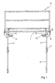
- Eine Ansicht der Bühne in Arbeitsstellung;
- Fig. 2
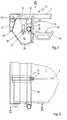
- eine gegenüber der Ansicht in Fig. 1 um 90° gedrehten Ansicht eines Einzelteiles in vergrößertem Maßstab in Richtung des Pfeiles II - II der Fig. 3;
- Fig. 3
- zeigt eine Aufsicht in Richtung des Pfeiles III der Fig. 2;
- Fig. 4
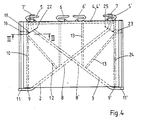
- eine Ansicht von unten im kleinerem Maßstab.
- Fig. 1
- A view of the stage in working position;
- Fig. 2
- a view of an individual part rotated by 90 ° relative to the view in FIG. 1 on an enlarged scale in the direction of the arrow II-II of FIG. 3;
- Fig. 3
- shows a plan in the direction of arrow III of Fig. 2;
- Fig. 4
- a bottom view on a smaller scale.
Bei der in der Zeichnung dargestellten Ausführungsform der Erfindung weist der klappbare Bühnenabschnitt einen Bühnenboden 1 auf, der auf zwei Stützen 2 und 3 sich abstützt, die bei der dargestellten Ausführungsform eine etwa dreieckige Form aufweisen. Der parallel zur Wandebene, bei aufgebauter Bühne senkrechte Stab 4 jeder Stütze weist in der Nähe seines oberen Endes einen Haken 5 bzw. 5' und etwa auf halber Höhe einen Haken 6 bzw. 6' auf, mit denen sie in entsprechende Schlaufen oder Schuhe eingehängt werden können, die in der Wand des Bauwerks befestigt sind und über die sich die Last der Bühne auf die Bauwerkswand überträgt. Am unteren Ende des senkrechten Stabes 4 befindet sich ebenfalls eine Vorrichtung 7 bzw. 7' zum Abstützen an der Wand. Von diesem unteren Ende der Stütze verläuft ein schräger Stab 8 bzw. 8' nach oben außen, wo er bei 9 bzw. 9' an einem Querstab 10 bzw. 24 befestigt und über die Befestigungsstelle 9 bzw. 9' hinaus noch einen Vorsprung 11 bzw. 11' aufweist. An dem der Stelle 9 abgewandten Ende ist der Querstab 10 mit dem senkrechten Stab 4, der Querstab 24 mit dem senkrechten Stab 4' starr verbunden. Zur Aussteifung der Stütze 3, die bei der dargestellten Ausführungsform ebenfalls wie die Stütze 2 die Form einer Konsole aufweist, dienen noch Aussteiffungsstäbe 12 und 13.In the embodiment of the invention shown in the drawing, the foldable stage section has a
An dem Bühnenboden sind noch Vorrichtungen vorgesehen, in denen ein als ganzes mit 14 bezeichnetes Geländer befestigt werden kann.Devices are also provided on the stage floor in which a railing, designated as a whole, can be attached.
Die Lagerung der Stützen 2 und 3 wird am einen Bühnenende in Verbindung mit der Stütze 2 beschrieben. Am anderen Ende der Bühne befindet sich zur Lagerung der Stütze 3 eine spiegelbildliche Anordnung. Der Querstab 10 bildet die Drehachse, um die die Konsole 2 an die Unterseite des Bühnenbodens 1 bei abgenommener Bühne herangeschwenkt werden kann. Hierzu dient ein Beschlag 15, der in Fig. 2 in größerem Maßstab dargestellt ist und der an beiden Enden des Querstabes 10 vorgesehen ist, also an der der Bauwerkswand zugewandten Innenseite der Bühne und an der der Bauwerkswand abgewandten äußeren Seite der Bühne. Der Beschlag 15 weist eine Platte 16 auf, die sich vom Rand des Bühnenbodens 1 nach unten erstreckt und zugleich einen Fuß 28 für die Abstützung der zusammengeklappten Bühne bildet. Die Platte 16 weist an ihrem nach innen gerichteten Rand 17 eine Auflage 18 für den Querstab 10 auf. In dem Beschlag 16 ist ein Stab 19 befestigt, der zusammen mit dem Rand 17 einen Schlitz 20 begrenzt, in dem der Querstab 10 sich rechtwinklig zur Ebene des Bühnenbodens 1 bewegen und damit seinen Abstand von der Unterfläche des Bühnenbodens verändern kann. Um den Stab 19 ist eine Schwenksicherung 21 schwenkbar gelagert, die eine Auflagefläche 22 aufweist.The storage of the
In der Arbeitsstellung, d.h. bei an der Bauwerkswand eingehängter und befestigter Bühne befindet sich der Querstab 10 am oberen Ende des Schlitzes 20 und stützt bei der dargestellten Ausführungsform unmittelbar den Bühnenboden 1 ab. Dies kann aber auch über entsprechende Zwischenstücke erfolgen. Wird die Bühne abgehängt, so bewegt sich durch das Gewicht der Stützen der Querstab an das untere Ende des Schlitzes 20. Hierauf werden die Stützen 2 und 3 eingeklappt.In the working position, ie when it is suspended on the building wall and attached stage, the
Die Schwenkachse 24 der Stütze 3 stützt sich wie erwähnt auf einem Beschlag ab, der an dem Ende des Bühnenbodens 1 angeordnet ist, das dem Ende des Bühnenbodens abgewandt ist, das in Fig. 2 dargestellt ist. Wird zunächst die Stütze 3 im Uhrzeigersinne um ihre Schwenkachse 24 zur Anlage an den Bühnenboden 1 verschwenkt, so wird die Sicherung 21 zunächst soweit um die Achse des Stabes 19 verschwenkt, daß das untere Ende 7' der Stütze 3 an der Schwenksicherung 21 vorbeigeschwenkt werden kann. Hierauf wird die Schwenksicherung 21 wieder in die Bahn des unteren Endes der Stütze 3 eingeschwenkt und dieses untere Ende auf der Auflagefläche 22 abgelegt. Dabei befindet sich der Querstab 24, der die Schwenkachse der Stütze 3 bildet, nach wie vor am unteren Ende des Schlitzes 20 des dort angeordneten Beschlages.The
Nun wird die Stütze 2 gegen Uhrzeigersinn um den Querstab 10 an die Unterseite des Bühnenbodens 1 herangeschwenkt und das untere Ende der Stütze 2 auf die Schwenksicherung 25 aufgelegt, die an einem Beschlag 23 angeordnet ist, der auf der dem Beschlag 16 entgegengesetzen Ende der Bühne angeordnet ist. Dabei kommt die Stütze an der bereits eingeschwenkten Stütze 3 zur Anlage und drückt diese Stütze nach oben, so daß deren Querstab 24 in das obere Ende des dortigen Schlitzes wandert. Da das Ende 7 der Stütze 2 auf der Schwenksicherung 25 und der Querstab 10 am unteren Ende des Schlitzes 20 aufliegt, verläuft die Stütze 2 eben und parallel zu dem Bühnenboden 1.Now the
An jedem seitlichen Ende der Bühne ist noch ein an der Schmalseite des Bühnenbodens befestigter Querträger 26 vorgesehen, dessen Schenkel 27 etwas weiter nach unten ragt als das Maß, das die beiden übereinandergeklappten Stützen 2 und 3 benötigen. Der Schenkel 27 reicht daher etwas weiter unter den Bühnenboden 1 herunter als die Auflage 18, die am unteren Schlitzende vorgesehen ist.At each side end of the stage there is also a
Die Platte 16, die den Fuß 28 für die zusammengeklappte Bühne bildet, reicht jedoch noch soweit nach unten, daß sich dann, wenn sich die Platte 16 auf einer Auflage abstützt, zwischen dem unteren Rand (Fuß 28) der Platte 16 und dem unteren Rand 29 des Schenkels 27 ein Zwischenraum verbleibt, der ausreicht, um mit der Gabel eines handelsüblichen Gabelstaplers bequem einfahren zu können. Beim Anheben liegt dann dieser untere Rand 29 auf dem Gabelstapler auf, dessen Gabel auch an dem Querrohr 10 anliegen kann, sofern an diesem Ende der Bühne der Querstab 10 in der unteren Position in dem Schlitz 20 sich befindet.The
In der Platte 16 befindet sich noch ein Langloch 30, in dem ein Bolzen 31 geführt ist, der an einer Kranöse 32 befestigt ist, die nach oben über den Boden 1 herausgezogen werden kann, wenn die Bühne an den Kranhaken angehängt werden soll.In the
Die Beschläge 16 und die entsprechenden Einrichtungen wie die Schwenksicherung können bei Ausführungsformen der Erfindung an allen vier Ecken des Bühnenboden 1 angeordnet sein. Zum einen weist dann die zusammengeklappte Bühne an jeder Ecke einen Fuß auf, zum andern sind zwar bei der Verwendung von dreieckigen Konsolen als Stützen die beiden am äußeren Rand befindlichen Schwenksicherungen ohne Funktion, sie können jedoch nützlich sein, wenn andere als dreieckige Konsolen als Stützen verwendet werden, beispielsweise rechteckige Rahmen.The
Der Beschlag 16 kann so ausgebildet sein, daß die Stützen abnehmbar an ihm befestigt sind, vorzugsweise formschlüssig ohne Verwendung von Schrauben.The fitting 16 can be designed so that the supports are removably attached to it, preferably in a form-fitting manner without the use of screws.
Die Erfindung läßt sich sowohl an ganzen Bühnen als auch an einzelnen Bühnenabschnitten verwirklichen.The invention can be implemented both on entire stages and on individual stage sections.
Claims (11)
- Staging for a scaffold, especially for use with concrete moulding, having supports which can be folded-up to the lower side of the staging floor, characterized in that the pivot axis (10, 24) of at least one of these supports (2, 3) can be moved at right angles to the surface of the staging floor (1).
- Staging according to claim 1, characterized in that the separation between the pivot-axis (10) of the support (2) and the lower surface of the staging floor can be changed by that amount assumed by an oppositely lying support (3) when folded-up to the lower side of the flooring.
- Staging according to claim 1 or 2, characterized in that fittings (16) are disposed on the lower side of the flooring to limit a slot (20) in which the component (10, 24) constituting the rotation axis of the support (2, 3) is guided in a rotatable and displaceable fashion.
- Staging according to claim 1 or 2, characterized in that motion of the rotation axis of the support for changing its separation from the lower side of the flooring is effected through a pivoting motion of at least one lever.
- Staging according to one of the preceding claims, characterized in that the staging comprises at least one base (28) with which an upper staging is supported on the next underlying staging or on a support surface when stacking a plurality of folded-up stagings upon one another.
- Staging according to claim 5 or 6, characterized in that the base (28) is disposed on at least one fitting (16) holding the staging supports.
- Staging according to claim 5 or 6, characterized in that the base (16, 28) is sufficiently long that an intermediate space remains between two stacked folded-up stagings at least at the narrow side, the height of which is somewhat larger then the thickness of the fork of a fork lift.
- Staging according to one of the preceding claims, characterized in that a rest (21, 22) is disposed at one end of the staging (1) into which the support borne on the opposite end of the staging can be inserted when folded-up to the staging floor.
- Staging according to one of the preceding claims, characterized in that a carrier means (26) is disposed in the vicinity of the staging flooring (1) which either longitudinally or transversely connects support bearing locations.
- Staging according to claim 5 through 10, characterized in that at least one base is disposed on the connecting carrier means (26).
- Staging according to one of the preceding claims, having narrow sides, characterized in that a carrier means (26) is disposed on the narrow sides whose width is such as to project downwardly below the lower surface of the staging floor by an amount exceeding the height taken in by two supports folded on top of each other and the lower edge (29) of this transverse carrier means (26) forms the support for a folded-up staging on the fork of a fork lift and the bases (16, 28) project downwardly to a sufficient extent to accommodate the fork of the fork lift in this intermediate space between two stacked folded-up stagings.
Applications Claiming Priority (2)
| Application Number | Priority Date | Filing Date | Title |
|---|---|---|---|
| DE4405289A DE4405289C1 (en) | 1994-02-19 | 1994-02-19 | Work platform for scaffolding, partic. for concrete sheathing |
| DE4405289 | 1994-02-19 |
Publications (2)
| Publication Number | Publication Date |
|---|---|
| EP0668418A1 EP0668418A1 (en) | 1995-08-23 |
| EP0668418B1 true EP0668418B1 (en) | 1997-04-09 |
Family
ID=6510620
Family Applications (1)
| Application Number | Title | Priority Date | Filing Date |
|---|---|---|---|
| EP95100037A Expired - Lifetime EP0668418B1 (en) | 1994-02-19 | 1995-01-03 | Scaffold |
Country Status (3)
| Country | Link |
|---|---|
| EP (1) | EP0668418B1 (en) |
| DE (2) | DE4447467C2 (en) |
| ES (1) | ES2102890T3 (en) |
Families Citing this family (1)
| Publication number | Priority date | Publication date | Assignee | Title |
|---|---|---|---|---|
| CN108797990A (en) * | 2018-06-15 | 2018-11-13 | 王秀丽 | A kind of construction plastering auxiliary device |
Family Cites Families (3)
| Publication number | Priority date | Publication date | Assignee | Title |
|---|---|---|---|---|
| US1837232A (en) * | 1929-10-21 | 1931-12-22 | Joseph Pavelka | Hinge for electric grids |
| CH266847A (en) * | 1949-01-28 | 1950-02-28 | Fehrenbach Joseph | Collapsible trestle. |
| FR2676771B1 (en) * | 1991-05-21 | 1995-08-25 | Al Cant Coffrages | IMPROVEMENT IN FOLDABLE SPROCKLES CONSOLES FOR SCAFFOLDING OR THE LIKE. |
-
1994
- 1994-02-19 DE DE4447467A patent/DE4447467C2/en not_active Expired - Fee Related
-
1995
- 1995-01-03 DE DE59500165T patent/DE59500165D1/en not_active Expired - Fee Related
- 1995-01-03 EP EP95100037A patent/EP0668418B1/en not_active Expired - Lifetime
- 1995-01-03 ES ES95100037T patent/ES2102890T3/en not_active Expired - Lifetime
Also Published As
| Publication number | Publication date |
|---|---|
| ES2102890T3 (en) | 1997-08-01 |
| DE4447467C2 (en) | 1997-02-06 |
| EP0668418A1 (en) | 1995-08-23 |
| DE4447467A1 (en) | 1995-08-31 |
| DE59500165D1 (en) | 1997-05-15 |
Similar Documents
| Publication | Publication Date | Title |
|---|---|---|
| DE1958347C2 (en) | Stackable loading frame with pivoting corner supports or end walls | |
| DE2145550C3 (en) | Collapsible container | |
| DE3039079A1 (en) | FOLDABLE CARGO CARRIAGE | |
| DE7534214U (en) | WORKBENCH WITH ONE OF THIS SUPPORTING FOLDABLE SUPPORT STRUCTURE | |
| EP2590867B1 (en) | Transport arrangement | |
| DE102009050871B4 (en) | Device for transporting hanging garments | |
| DE4113314A1 (en) | Universal stacking support frame for transport and storage purposes - has four cylindrical tubes at corners of rectangular metal frame | |
| EP2217505B1 (en) | Transport arrangement | |
| DE1917833A1 (en) | Collapsible loading pallet | |
| EP0668418B1 (en) | Scaffold | |
| DE2943274C2 (en) | Stacking protection, consisting of at least one angle rail resting against a vertical stacking edge | |
| DE4405289C1 (en) | Work platform for scaffolding, partic. for concrete sheathing | |
| DE4135677A1 (en) | Collapsible load support with pallet base - has swivel hinged parts making up side walls for easier assembly and dismantling | |
| AT390421B (en) | AT LEAST TWO USE OF STACKING RACKS FOR STACKING LONG AND / OR AREA OBJECTS, SUCH AS SWITCHBOARDS, KANTHOELZER, BOARDS OR THE LIKE. | |
| EP0642980B1 (en) | Pallet for storing and transporting of objects | |
| EP1484278B1 (en) | Device, stacker crane and shelf storage for moving pallets in and out of storage | |
| DE3124360A1 (en) | Container provided with feet, in particular a stackable container for agricultural and industrial purposes | |
| DE3728647A1 (en) | Pallet with protection and stacking bars | |
| DE1193430B (en) | Attachment frame for pallets with a right-angled loading area | |
| DE10349656B4 (en) | Pallet for transporting stacked objects | |
| EP0625619A1 (en) | Scaffolding platform | |
| DE1586870C (en) | Collapsible frame for pallets | |
| DE3117012A1 (en) | Protective cage for crane forks | |
| DE10028404A1 (en) | Stackable table or seat has three-sided, open frame which can be nested with other, similar frames and removable flat support or working surface which is held on it by support bars at top | |
| DE10324358A1 (en) | Cradle for transporting panes of glass or windows is made up of two uprights connected by hinges to cross-bars and has diagonal braces which fit into U-profiles on these, allowing cradle to be folded for stacking |
Legal Events
| Date | Code | Title | Description |
|---|---|---|---|
| PUAI | Public reference made under article 153(3) epc to a published international application that has entered the european phase |
Free format text: ORIGINAL CODE: 0009012 |
|
| AK | Designated contracting states |
Kind code of ref document: A1 Designated state(s): DE ES FR GB IT |
|
| 17P | Request for examination filed |
Effective date: 19950810 |
|
| GRAG | Despatch of communication of intention to grant |
Free format text: ORIGINAL CODE: EPIDOS AGRA |
|
| GRAH | Despatch of communication of intention to grant a patent |
Free format text: ORIGINAL CODE: EPIDOS IGRA |
|
| 17Q | First examination report despatched |
Effective date: 19960902 |
|
| GRAH | Despatch of communication of intention to grant a patent |
Free format text: ORIGINAL CODE: EPIDOS IGRA |
|
| GRAA | (expected) grant |
Free format text: ORIGINAL CODE: 0009210 |
|
| ITF | It: translation for a ep patent filed |
Owner name: 0403;74TOFPATRITO BREVETTI |
|
| AK | Designated contracting states |
Kind code of ref document: B1 Designated state(s): DE ES FR GB IT |
|
| GBT | Gb: translation of ep patent filed (gb section 77(6)(a)/1977) |
Effective date: 19970410 |
|
| REF | Corresponds to: |
Ref document number: 59500165 Country of ref document: DE Date of ref document: 19970515 |
|
| ET | Fr: translation filed | ||
| REG | Reference to a national code |
Ref country code: ES Ref legal event code: FG2A Ref document number: 2102890 Country of ref document: ES Kind code of ref document: T3 |
|
| PLBE | No opposition filed within time limit |
Free format text: ORIGINAL CODE: 0009261 |
|
| STAA | Information on the status of an ep patent application or granted ep patent |
Free format text: STATUS: NO OPPOSITION FILED WITHIN TIME LIMIT |
|
| 26N | No opposition filed | ||
| REG | Reference to a national code |
Ref country code: GB Ref legal event code: IF02 |
|
| PGFP | Annual fee paid to national office [announced via postgrant information from national office to epo] |
Ref country code: FR Payment date: 20030124 Year of fee payment: 9 |
|
| PGFP | Annual fee paid to national office [announced via postgrant information from national office to epo] |
Ref country code: GB Payment date: 20030127 Year of fee payment: 9 |
|
| PGFP | Annual fee paid to national office [announced via postgrant information from national office to epo] |
Ref country code: ES Payment date: 20030130 Year of fee payment: 9 |
|
| PG25 | Lapsed in a contracting state [announced via postgrant information from national office to epo] |
Ref country code: GB Free format text: LAPSE BECAUSE OF NON-PAYMENT OF DUE FEES Effective date: 20040103 |
|
| PG25 | Lapsed in a contracting state [announced via postgrant information from national office to epo] |
Ref country code: ES Free format text: LAPSE BECAUSE OF NON-PAYMENT OF DUE FEES Effective date: 20040105 |
|
| GBPC | Gb: european patent ceased through non-payment of renewal fee |
Effective date: 20040103 |
|
| PG25 | Lapsed in a contracting state [announced via postgrant information from national office to epo] |
Ref country code: FR Free format text: LAPSE BECAUSE OF NON-PAYMENT OF DUE FEES Effective date: 20040930 |
|
| REG | Reference to a national code |
Ref country code: FR Ref legal event code: ST |
|
| PG25 | Lapsed in a contracting state [announced via postgrant information from national office to epo] |
Ref country code: IT Free format text: LAPSE BECAUSE OF NON-PAYMENT OF DUE FEES;WARNING: LAPSES OF ITALIAN PATENTS WITH EFFECTIVE DATE BEFORE 2007 MAY HAVE OCCURRED AT ANY TIME BEFORE 2007. THE CORRECT EFFECTIVE DATE MAY BE DIFFERENT FROM THE ONE RECORDED. Effective date: 20050103 |
|
| REG | Reference to a national code |
Ref country code: ES Ref legal event code: FD2A Effective date: 20040105 |
|
| PGFP | Annual fee paid to national office [announced via postgrant information from national office to epo] |
Ref country code: DE Payment date: 20090122 Year of fee payment: 15 |
|
| PG25 | Lapsed in a contracting state [announced via postgrant information from national office to epo] |
Ref country code: DE Free format text: LAPSE BECAUSE OF NON-PAYMENT OF DUE FEES Effective date: 20100803 |