EP0667312B1 - Schlauchhaspel - Google Patents
Schlauchhaspel Download PDFInfo
- Publication number
- EP0667312B1 EP0667312B1 EP19950200318 EP95200318A EP0667312B1 EP 0667312 B1 EP0667312 B1 EP 0667312B1 EP 19950200318 EP19950200318 EP 19950200318 EP 95200318 A EP95200318 A EP 95200318A EP 0667312 B1 EP0667312 B1 EP 0667312B1
- Authority
- EP
- European Patent Office
- Prior art keywords
- shaft end
- reel
- valve case
- hose
- reel hub
- Prior art date
- Legal status (The legal status is an assumption and is not a legal conclusion. Google has not performed a legal analysis and makes no representation as to the accuracy of the status listed.)
- Expired - Lifetime
Links
Images


Classifications
-
- F—MECHANICAL ENGINEERING; LIGHTING; HEATING; WEAPONS; BLASTING
- F16—ENGINEERING ELEMENTS AND UNITS; GENERAL MEASURES FOR PRODUCING AND MAINTAINING EFFECTIVE FUNCTIONING OF MACHINES OR INSTALLATIONS; THERMAL INSULATION IN GENERAL
- F16K—VALVES; TAPS; COCKS; ACTUATING-FLOATS; DEVICES FOR VENTING OR AERATING
- F16K5/00—Plug valves; Taps or cocks comprising only cut-off apparatus having at least one of the sealing faces shaped as a more or less complete surface of a solid of revolution, the opening and closing movement being predominantly rotary
- F16K5/04—Plug valves; Taps or cocks comprising only cut-off apparatus having at least one of the sealing faces shaped as a more or less complete surface of a solid of revolution, the opening and closing movement being predominantly rotary with plugs having cylindrical surfaces; Packings therefor
- F16K5/0457—Packings
- F16K5/0478—Packings on the plug
-
- B—PERFORMING OPERATIONS; TRANSPORTING
- B65—CONVEYING; PACKING; STORING; HANDLING THIN OR FILAMENTARY MATERIAL
- B65H—HANDLING THIN OR FILAMENTARY MATERIAL, e.g. SHEETS, WEBS, CABLES
- B65H75/00—Storing webs, tapes, or filamentary material, e.g. on reels
- B65H75/02—Cores, formers, supports, or holders for coiled, wound, or folded material, e.g. reels, spindles, bobbins, cop tubes, cans, mandrels or chucks
- B65H75/34—Cores, formers, supports, or holders for coiled, wound, or folded material, e.g. reels, spindles, bobbins, cop tubes, cans, mandrels or chucks specially adapted or mounted for storing and repeatedly paying-out and re-storing lengths of material provided for particular purposes, e.g. anchored hoses, power cables
- B65H75/38—Cores, formers, supports, or holders for coiled, wound, or folded material, e.g. reels, spindles, bobbins, cop tubes, cans, mandrels or chucks specially adapted or mounted for storing and repeatedly paying-out and re-storing lengths of material provided for particular purposes, e.g. anchored hoses, power cables involving the use of a core or former internal to, and supporting, a stored package of material
- B65H75/44—Constructional details
- B65H75/4478—Constructional details relating to handling of fluids
Definitions
- the invention relates to a hose reel, in particular for a fire-hose, in which is incorporated a valve which automatically opens the water supply as soon as the hose is unrolled and closes it again when the hose is rolled up.
- Such a reel is known from the Netherlands patent application 8 502 159.
- a reel hub is arranged in otherwise usual manner for rotation on a fixedly disposed shaft end which is mounted for instance on a wall.
- the reel hub is provided with co-rotatable hose connecting means.
- a water supply channel extends internally through the shaft end and can be placed in connection with the hose connecting means through radial openings in the shaft end and the reel hub, so that water can flow to the hose via this water supply channel.
- a rotatable valve case is mounted which can close or leave open a radial opening to the hose connecting means.
- the respective closed and open positions are determined by stop means.
- a friction coupling is arranged which is connected on one side to the valve case and on the other side to the reel hub, so that when the reel hub turns the valve case is carried along through the stroke permitted by the stop means.
- the known device is rather complicated and comprises comparatively many components.
- the known hose reel is thereby relatively expensive.
- the invention now has for its object to provide a hose reel of the above specified type which is of simpler construction and has fewer components, while it can nevertheless function with at least the same reliability.
- the friction coupling can be embodied in very simple manner in that it engages on one side on the fixed shaft end and on the other side onto the valve case rotatable directly therearound.
- a favourable embodiment of the friction coupling is herein characterized in claim 2.
- the step of claim 3 achieves in favourable manner that the bias of the friction coupling and therewith the carrying friction force can be adjusted simply by tightening the axial bolt connection to a greater or lesser extent.
- a further favorable embodiment is characterized in claim 4.
- the cam and the protrusion can hereby be arranged externally in simple manner and do not require any separate mounting operations.
- the step of claim 5 is preferably applied.
- the O-ring providing the sealing remains reliably enclosed in the groove and also cannot come loose of the groove during movement past the corresponding radial opening because it remains enclosed by the remaining wall parts between the smaller openings therein.
- the reel comprises a drum 1 with side flanges 2 which is mounted on a hub 3, which is arranged rotatably on a hollow shaft end 4.
- the latter is provided with a suspension slot 5 for fixing of the reel in a suspension plate arranged for instance on a wall, and with a connection 7 which is connected to a water supply pipe 6.
- Hub 3 has a connection 23 into which is fixedly screwed a coupling piece 8 which connects onto the one end of the hose 9 wound round the reel 1, 2.
- hub 3 is arranged rotatably round a valve case or valve member 10.
- a valve case or valve member 10 Arranged in the wall of the valve member is an opening 11 which forms a connection between the central cavity of shaft end 4 and a chamber 12 which is formed in shaft end 4 so that, when the still to be described valve member is located in the open position, water can flow from supply pipe 6 into the connection 23 and therefrom into the hose 9.
- valve member 10 Located inside the hub 3 is a rotatable valve member 10 which is formed by a case having thereon one or more cams 21 and a chamber 20 forming an annular end face. In the wall of valve member 10 is arranged an opening 11 which, in the shown position of valve member 10, coincides with openings 14, so that this shown position of valve member 10 is the open position. By rotating hub 3 through about 30° the openings 14 are placed out of coincidence with openings 11 whereby valve member 10 is situated in the closed position.
- valve member 10 is held relative to shaft end 4 by an elastic intermediate disc 15 which, under bias generated by the disc 16, is pressed against the annular end face 20.
- Disc 16 cannot turn tangentially relative to shaft end 4 and the disc 16 is biased by axial displacement by means of a nut 17 which is arranged on a threaded portion 28 of plug 18.
- the plug 18 is screwed into shaft end 4.
- Valve member 10 is thus held in place by friction between surfaces 27 of the intermediate disc 15 and end face 20 of valve member 10 or friction between the surfaces 29 of intermediate disc 15 and 30 of disc 16.
- the openings 14 of hub 3 will coincide with the opening 11 of valve member 10 after unwinding of the hose through roughly 300°, so that the member 10 is opened.
- the cam 24 of hub 3 runs against a cam 21 of valve member 10.
- the valve member 10 will hereby begin to co-rotate with hub 3 round shaft end 4 and intermediate disc 15 will begin to slip against valve member 10 or disc 16.
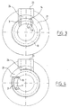
- valve member 10 is provided with a radial opening 11 which is sealed by a special seal groove 22 in which sealing ring 19 is arranged.
- sealing ring 19 is formed by a number of holes 26 such that wall-like parts remain which hold the sealing ring 19 pressed in, also in the case of strong water flows.
- Fig. 7 shows a preferred embodiment wherein slot-like holes 25 are applied. Here also the remaining wall parts enclose the sealing ring 19.
Landscapes
- Engineering & Computer Science (AREA)
- General Engineering & Computer Science (AREA)
- Mechanical Engineering (AREA)
- Storage Of Web-Like Or Filamentary Materials (AREA)
- Manufacturing Of Electric Cables (AREA)
- Fire-Extinguishing By Fire Departments, And Fire-Extinguishing Equipment And Control Thereof (AREA)
- Storing, Repeated Paying-Out, And Re-Storing Of Elongated Articles (AREA)
Claims (6)
- Schlauchhaspel mit einem fest angeordneten Schaftende (4), einer Haspelnabe (3), die drehbar an das Schaftende (4) montiert ist und die mit sich mitdrehenden Schlauchanschlußmitteln (23) versehen ist, in welchen ein Wasserzuführkanal definiert ist, der sich im Inneren durch das Schaftende (4) erstreckt und über radiale Öffnungen in dem Schaftende und der Haspelnabe mit den Schlauchanschlußmitteln in Verbindung steht, und wobei die Haspelnabe (3) mit einem sich mitdrehenden Ventilgehäuse (10) versehen ist, das direkt um das Schaftende (4) liegt und um einen Winkel relativ zur Haspelnabe (3) zwischen einer geschlossenen Position, in der die sich darin befindliche radiale Öffnung blockiert ist, und einer offenen Position, in der sie offengelassen ist, drehbar ist,
dadurch gekennzeichnet, daß das Ventilgehäuse (10) drehbar auf dem Schaftende (4) angeordnet ist und die Haspelnabe (3) drehbar auf dem Ventilgehäuse (10) angeordnet ist und daß eine Reibungskupplung vorgesehen ist, die bei Rotation der Haspelnabe in das Ventilgehäuse eingreift und dieses in die offene Position dreht und umgekehrt, und daß die Reibungskupplung in das Schaftende (4) und das Kupplungsgehäuse (10) eingreift. - Schlauchhaspel nach Anspruch 1,
wobei die Reibungskupplung eine Scheibe (16) aufweist, die fest an der Endfläche des Schaftendes (4) befestigt ist und die über eine Schicht (15) aus Reibungsmaterial mit Vorspannung an einer ringförmigen Axialfläche des Ventilgehäuses (10) anliegt. - Schlauchhaspel nach Anspruch 2,
wobei die Scheibe (16) mit dem Schaftende (4) mittels einer Axialbolzenverbindung verbunden ist. - Schlauchhaspel nach Anspruch 2 oder 3,
wobei die ringförmige Axialfläche des Ventilgehäuses (10) einen Radialnocken (24) aufweist, der mit einem Vorsprung an der Haspelnabe (3) zusammenwirkt, um die Rotationspositionen des Ventilgehäuses (10) entsprechend der offenen und geschlossenen Position zu definieren. - Schlauchhaspel nach einem der vorstehenden Ansprüche,
wobei das Ventilgehäuse (10) eine radiale Öffnung (11) hat, die in der offenen Position mit der radialen Öffnung (14) in der Haspelnabe (3) übereinstimmt, und in den einander zugewandten zylindrischen Flächen des Ventilgehäuses (10) und der Haspelnabe (3) eine Nut ausgebildet ist, die um diese Öffnungen herum verläuft, in welcher ein O-Ring (19) angeordnet ist, und die andere Öffnung (14) aus einer Anzahl kleinerer Öffnungen (25, 26) mit dazwischen verbliebenen Wandteilen gebildet ist. - Schlauchkupplung nach Anspruch 5,
wobei die kleineren Öffnungen langgestreckte Öffnungen (25) in tangentialer Richtung sind.
Applications Claiming Priority (2)
| Application Number | Priority Date | Filing Date | Title |
|---|---|---|---|
| NL9400203A NL9400203A (nl) | 1994-02-09 | 1994-02-09 | Slanghaspel. |
| NL9400203 | 1994-02-09 |
Publications (2)
| Publication Number | Publication Date |
|---|---|
| EP0667312A1 EP0667312A1 (de) | 1995-08-16 |
| EP0667312B1 true EP0667312B1 (de) | 1999-04-21 |
Family
ID=19863814
Family Applications (1)
| Application Number | Title | Priority Date | Filing Date |
|---|---|---|---|
| EP19950200318 Expired - Lifetime EP0667312B1 (de) | 1994-02-09 | 1995-02-09 | Schlauchhaspel |
Country Status (4)
| Country | Link |
|---|---|
| EP (1) | EP0667312B1 (de) |
| DE (1) | DE69509149T2 (de) |
| NL (1) | NL9400203A (de) |
| NO (1) | NO310698B1 (de) |
Cited By (2)
| Publication number | Priority date | Publication date | Assignee | Title |
|---|---|---|---|---|
| DE102010026118A1 (de) | 2010-07-05 | 2012-01-05 | Mkn Maschinenfabrik Kurt Neubauer Gmbh & Co. | Schlauchaufrollsystem und damit ausgerüstetes Gargerät |
| WO2012175564A1 (de) | 2011-06-23 | 2012-12-27 | Mkn Maschinenfabrik Kurt Neubauer Gmbh & Co. | Gargerät mit einem tiegel und verfahren zur reinigung des tiegels |
Families Citing this family (2)
| Publication number | Priority date | Publication date | Assignee | Title |
|---|---|---|---|---|
| EP0937674B1 (de) * | 1998-02-13 | 2002-03-27 | eloma GmbH Grossküchentechnik | Schlauchaufrollsystem |
| FR2807419B1 (fr) * | 2000-04-11 | 2003-02-07 | Pok Soc | Devidoir pour tuyau semi-rigide |
Family Cites Families (2)
| Publication number | Priority date | Publication date | Assignee | Title |
|---|---|---|---|---|
| US2578396A (en) * | 1945-10-12 | 1951-12-11 | Dole Valve Co | Valve and sealing structure therefor |
| NL8502159A (nl) * | 1985-07-30 | 1987-02-16 | Pieter Van T Veer | Slanghaspel. |
-
1994
- 1994-02-09 NL NL9400203A patent/NL9400203A/nl active Search and Examination
-
1995
- 1995-02-08 NO NO19950458A patent/NO310698B1/no not_active IP Right Cessation
- 1995-02-09 DE DE1995609149 patent/DE69509149T2/de not_active Expired - Lifetime
- 1995-02-09 EP EP19950200318 patent/EP0667312B1/de not_active Expired - Lifetime
Cited By (5)
| Publication number | Priority date | Publication date | Assignee | Title |
|---|---|---|---|---|
| DE102010026118A1 (de) | 2010-07-05 | 2012-01-05 | Mkn Maschinenfabrik Kurt Neubauer Gmbh & Co. | Schlauchaufrollsystem und damit ausgerüstetes Gargerät |
| EP2404858A2 (de) | 2010-07-05 | 2012-01-11 | MKN Maschinenfabrik Kurt Neubauer GmbH & Co. | Schlauchaufrollsystem und damit ausgerüstetes Gargerät |
| EP2404858A3 (de) * | 2010-07-05 | 2013-08-07 | MKN Maschinenfabrik Kurt Neubauer GmbH & Co. KG | Schlauchaufrollsystem und damit ausgerüstetes Gargerät |
| WO2012175564A1 (de) | 2011-06-23 | 2012-12-27 | Mkn Maschinenfabrik Kurt Neubauer Gmbh & Co. | Gargerät mit einem tiegel und verfahren zur reinigung des tiegels |
| DE102011105716A1 (de) | 2011-06-23 | 2012-12-27 | MKN Maschinenfabrik Kurt Neubauer GmbH & Co. KG | Gargerät mit einem Tiegel und Verfahren zur Reinigung des Tiegels |
Also Published As
| Publication number | Publication date |
|---|---|
| NL9400203A (nl) | 1995-09-01 |
| DE69509149T2 (de) | 1999-08-12 |
| NO950458L (no) | 1995-08-10 |
| EP0667312A1 (de) | 1995-08-16 |
| NO950458D0 (no) | 1995-02-08 |
| NO310698B1 (no) | 2001-08-13 |
| DE69509149D1 (de) | 1999-05-27 |
Similar Documents
| Publication | Publication Date | Title |
|---|---|---|
| US5697557A (en) | Shower head with switching mechanism | |
| US5651280A (en) | Door lock | |
| US6899171B2 (en) | Actuating device | |
| US5076918A (en) | Quick change oil filter | |
| EP0667312B1 (de) | Schlauchhaspel | |
| CA1319138C (en) | Disk valve | |
| JPH10142251A (ja) | 流水検知装置 | |
| US6202695B1 (en) | Water faucet control cartridge | |
| US3612094A (en) | Remote control hide-away hose | |
| US6446894B1 (en) | Planetary gear assembly for fishing reel | |
| CA1053214A (en) | Seal member for faucet valve | |
| US6189561B1 (en) | Valve cartridge for lift valve having the closing pressure on the sealing limited | |
| US6105484A (en) | Lockout device for valve actuators | |
| JP4176839B2 (ja) | 制限された封止に基づく閉止圧力を有する揚水弁用の弁カートリッジ | |
| JP3631844B2 (ja) | 流水検知装置 | |
| JPS59113375A (ja) | 流体弁 | |
| FR2432663A1 (fr) | Dispositif de reglage de la vitesse d'ouverture ou de fermeture d'un clapet a battant | |
| US4311287A (en) | Web pay-out assembly | |
| SU1583693A1 (ru) | Система управлени шаровым краном | |
| CN1963254A (zh) | 间歇式卷绕单元 | |
| GB2240538A (en) | Hose reel | |
| US4081172A (en) | Fluid valve | |
| AU625853B2 (en) | A disc valve | |
| IE900397A1 (en) | A hose-reel | |
| SU1236439A1 (ru) | Клапан перепада давлений |
Legal Events
| Date | Code | Title | Description |
|---|---|---|---|
| PUAI | Public reference made under article 153(3) epc to a published international application that has entered the european phase |
Free format text: ORIGINAL CODE: 0009012 |
|
| AK | Designated contracting states |
Kind code of ref document: A1 Designated state(s): BE DE FR NL |
|
| 17P | Request for examination filed |
Effective date: 19960214 |
|
| 17Q | First examination report despatched |
Effective date: 19970702 |
|
| GRAG | Despatch of communication of intention to grant |
Free format text: ORIGINAL CODE: EPIDOS AGRA |
|
| GRAG | Despatch of communication of intention to grant |
Free format text: ORIGINAL CODE: EPIDOS AGRA |
|
| GRAH | Despatch of communication of intention to grant a patent |
Free format text: ORIGINAL CODE: EPIDOS IGRA |
|
| GRAH | Despatch of communication of intention to grant a patent |
Free format text: ORIGINAL CODE: EPIDOS IGRA |
|
| GRAA | (expected) grant |
Free format text: ORIGINAL CODE: 0009210 |
|
| AK | Designated contracting states |
Kind code of ref document: B1 Designated state(s): BE DE FR NL |
|
| REF | Corresponds to: |
Ref document number: 69509149 Country of ref document: DE Date of ref document: 19990527 |
|
| ET | Fr: translation filed | ||
| PLBE | No opposition filed within time limit |
Free format text: ORIGINAL CODE: 0009261 |
|
| STAA | Information on the status of an ep patent application or granted ep patent |
Free format text: STATUS: NO OPPOSITION FILED WITHIN TIME LIMIT |
|
| 26N | No opposition filed | ||
| PGFP | Annual fee paid to national office [announced via postgrant information from national office to epo] |
Ref country code: NL Payment date: 20140228 Year of fee payment: 20 Ref country code: DE Payment date: 20140226 Year of fee payment: 20 |
|
| PGFP | Annual fee paid to national office [announced via postgrant information from national office to epo] |
Ref country code: BE Payment date: 20140226 Year of fee payment: 20 Ref country code: FR Payment date: 20140228 Year of fee payment: 20 |
|
| REG | Reference to a national code |
Ref country code: DE Ref legal event code: R071 Ref document number: 69509149 Country of ref document: DE |
|
| REG | Reference to a national code |
Ref country code: NL Ref legal event code: V4 Effective date: 20150209 |