EP0666782B1 - Belt accumulator - Google Patents
Belt accumulator Download PDFInfo
- Publication number
- EP0666782B1 EP0666782B1 EP94922166A EP94922166A EP0666782B1 EP 0666782 B1 EP0666782 B1 EP 0666782B1 EP 94922166 A EP94922166 A EP 94922166A EP 94922166 A EP94922166 A EP 94922166A EP 0666782 B1 EP0666782 B1 EP 0666782B1
- Authority
- EP
- European Patent Office
- Prior art keywords
- tape
- ring
- strip
- belt
- roller
- Prior art date
- Legal status (The legal status is an assumption and is not a legal conclusion. Google has not performed a legal analysis and makes no representation as to the accuracy of the status listed.)
- Expired - Lifetime
Links
Images

Classifications
-
- B—PERFORMING OPERATIONS; TRANSPORTING
- B21—MECHANICAL METAL-WORKING WITHOUT ESSENTIALLY REMOVING MATERIAL; PUNCHING METAL
- B21C—MANUFACTURE OF METAL SHEETS, WIRE, RODS, TUBES OR PROFILES, OTHERWISE THAN BY ROLLING; AUXILIARY OPERATIONS USED IN CONNECTION WITH METAL-WORKING WITHOUT ESSENTIALLY REMOVING MATERIAL
- B21C49/00—Devices for temporarily accumulating material
-
- B—PERFORMING OPERATIONS; TRANSPORTING
- B65—CONVEYING; PACKING; STORING; HANDLING THIN OR FILAMENTARY MATERIAL
- B65H—HANDLING THIN OR FILAMENTARY MATERIAL, e.g. SHEETS, WEBS, CABLES
- B65H20/00—Advancing webs
- B65H20/30—Arrangements for accumulating surplus web
-
- B—PERFORMING OPERATIONS; TRANSPORTING
- B65—CONVEYING; PACKING; STORING; HANDLING THIN OR FILAMENTARY MATERIAL
- B65H—HANDLING THIN OR FILAMENTARY MATERIAL, e.g. SHEETS, WEBS, CABLES
- B65H2408/00—Specific machines
- B65H2408/20—Specific machines for handling web(s)
- B65H2408/21—Accumulators
- B65H2408/211—Coil type accumulator
Definitions
- the invention relates to a tape storage device, consisting of an outer ring of drivable support rollers arranged radially with respect to the vertical ring axis for the upright inclusion of an outer tape roll with a tape feed from the outside, from a concentric inner ring of freely rotatable, radial support rollers for one with the outer tape roll by a deflection loop connected inner tape reel and from a roll core for the inner tape reel forming roller cage, from the axially parallel rollers one of which leads the tape as a discharge roller to an inclined take-off roller within the roller cage.
- the metal band entering the band store is wound from the outside onto an outer band wrap which rests on its edge on an annular rotary table or on an outer ring of drivable, preferably conical, idler rollers. Since this outer tape roll does not require a roll cage as the winding core, the inner diameter of the outer tape roll is only determined by the ratio of the tape feed speed to the number of revolutions of the table.
- the tape runs over a deflection loop to an inner tape roll, which is received by an inner ring provided within the annular turntable of freely rotatable supporting rollers and is supported on a winding core from a roller basket, which encloses an inclined take-off roller, via which Tape is pulled from the inside of the inner tape reel in the opposite direction to the direction of rotation of the incoming tape by a basket roller serving as a reel roll from the tape store.
- the tape is wound up with the same number of turns on the two tape coils during storage due to the deflection loop rotating at a speed corresponding to half the difference between the tape entry and the tape exit speed.
- the size of the deflection loop depends on the strip thickness and, in particular in the case of thicker strips, requires comparatively large bending radii, which requires correspondingly large outside diameters for the rotary table.
- the compressive forces exerted on the belt in the region of the deflection loop on the side of the outer belt winding can cause the belt to buckle.
- the position of the outer tape roll on the turntable is not stable due to various influences.
- the invention is therefore based on the object to improve a tape store of the type described with simple constructive means that it is suitable for thin as well as for thick sheet metal strips that its outer diameter can be chosen to be comparatively small regardless of the respective strip thickness and that there is a stable position for the outer tape winding.
- the invention solves this problem in that, in a tape storage device of the type mentioned, between the outer and the inner ring of the idler rollers for the deflection loop around the ring axis with a revolution speed corresponding to half the difference between the tape feed and the tape run speed of the memory Drivable deflection roller is provided and that the outer ring of the idler rollers has a ring of inclined rollers on the inside, which rise radially inwards and / or incline with respect to a radial orientation with respect to the ring axis in the opposite direction to the direction of rotation of the outer tape roll.
- the bending radius for the deflection loop of the tape is determined by the radius of the deflection roller and not by that of the tape thickness and the belt material dependent, free bending behavior of the belt, so that when the deflection roller is designed for the smallest permissible bending radius of the belt, which requires the largest bending radius from the belts suitable for the storage device, all the belts form the same deflection loops and the outer diameter of the belt storage device also for thick bands can be kept comparatively small.
- the tensile forces exerted on the belt in the area of the deflection loop by the deflection roller not only ensure that the belt is attached to the sheathing of the deflection roller, but also enable thin strips to be stored, because it is no longer possible to buckle due to pressure forces otherwise occurring in the deflection area.
- the outer tape reel In order to be able to take full advantage of a deflecting roller rotating between the two tape reels for the tape deflection, it must be ensured that the outer tape reel is in a stable position, which is not supported by a roller cage or the like.
- the ring of inclined rollers is provided, which, due to their inclined position, urge the inner turns of the outer tape roll reaching their area radially outward, so that a stable state of equilibrium results.
- the inclined rollers can be inclined both about an axis running in the circumferential direction of the tape roll and about a vertical axis.
- the position of the inner windings of the outer tape reel can be determined, so that constant working conditions exist for the loop-forming deflection roller between the two tape reels.
- the inclined rollers can be provided with a thrust collar in the area of their inner end, which results in a guide for the inner winding of the tape winding without hindering the unwinding of the innermost tape winding.
- the support rollers of the outer ring can be arranged sloping inwards, which also supports the stabilization of the position of the outer tape roll.
- the control of the drive for the deflection roller between the two tape reels must be controlled as a function of the tape feed and tape speed of the tape storage.
- the speed control of the drive for the deflection roller can control the torque as a function of the thickness and the width of the tape to be stored. This allows an advantageous adaptation to the tape to be stored with regard to the deflection conditions in the region of the deflection loop between the two tape reels.
- the tape storage device essentially consists of a frame 2 which surrounds a table 1 in an annular manner and which carries an outer rim of driven support rollers 3 which are aligned radially with respect to the rim axis for the upright reception of an outer tape roll 4a.
- the table 1 has a concentric inner ring of likewise radially oriented support rollers 5, which are freely rotatable and extend radially outward from a roller cage 6, as can be seen in particular from FIG. 2.
- an inclined take-off roller 7 is provided, to which the belt 8 is fed from a discharge roller 9, which forms one of the rollers 10 of the roller cage 6.
- a deflection roller 11 is provided, which is freely rotatably mounted on an arm 12 of a rotating ring 13 and can be rotated around the table 1 with this rotating ring 13.
- the turntable 13 which is rotatably mounted on the table 1 is provided with a toothed ring 14 which meshes with a pinion 15.
- a motor 18 connected via a propeller shaft 16 to a gear 17 is provided, so that with the aid of the deflection roller 11 between the outer tape roll 4a and an inner tape roll 4b, which is wound onto the roller cage 6 and edgewise on the Supports support rollers 5 of the inner ring, a deflection loop 19 can be pulled, to the A support roller 20 is supported on the arm 12 for the deflection roller 11.
- the band 8 which runs into the band storage device via a band inlet 21 formed from a pair of rollers, reaches the support rollers 3 of the outer ring, which according to FIG. 1 are driven by a motor 22 with the interposition of a corresponding gear 23 via articulated shafts 24 and angular drives 25.
- the belt conveyance via the driven idler rollers 3 of the outer ring causes the band entering the band storage device to be wound into a band wrap 4a on the idler rollers 3.
- a ring of oblique rollers 26 is assigned to the outside of the idler rollers 3 on the inside, which according to the exemplary embodiment on the one hand rise towards the ring axis (FIG.
- the tape From the innermost turn of the outer tape roll 4a, the tape merges in a deflection loop 19 into the inner tape roll 4b, which is wound onto the roller cage 6 from the outside, the tape 8 moving inward from the innermost turn via the discharge roller 9 to the inclined take-off roller 7 from which it runs out of the tape storage.
- the deflection roller 11 rotates at half the tape feed speed, which Tape with the same number of turns is wound on the inner and outer tapes 4b and 4a.
- the deflection roller 11 moves in the opposite direction to the winding direction at half the tape running speed, and the tape turns are removed evenly from both the outer and the inner tape roll.
- a control device 28 is provided, which is connected on the one hand to a speed sensor 29 for the tape 8 entering the tape store and on the other hand to a speed transmitter 30 for the tape leaving the tape store, as is indicated in the block diagram in FIG. 1.
- the motor 18 is controlled for the deflection roller 11, by means of which the deflection loop 19 is advantageously formed, largely independently of the sizes and properties of the belt used in each case.
- the torque of the motor can also be regulated via the control device 28.
- the strip thickness is input via an input 31 into the control device 28, which, based on a predetermined dependency between the strip thickness and the required torque, presents a setpoint torque which is compared with the actual torque detected via a torque sensor 32, so that a corresponding difference between the setpoint and actual value Adjustment can take place.
- additional influencing variables such as the width of the strip to be stored or material properties, for controlling the torque of the motor 18 and thus the effective tensile stresses in the region of the deflection loop 19 can be taken into account.
- an outer roller basket 33 is provided, the basket rollers of which are designated by 34.
- This roller cage 33 is, however, not absolutely necessary for the actual tape storage in two opposite tape coils 4a and 4b connected by a deflection loop 19, as are the support rollers 35 and 36 for the tape in the area between the discharge roller 9 and the take-off roller 7, and for that leaking belt after the take-off roll can possibly be omitted.
Landscapes
- Engineering & Computer Science (AREA)
- Mechanical Engineering (AREA)
- Winding Of Webs (AREA)
- Winding, Rewinding, Material Storage Devices (AREA)
- Advancing Webs (AREA)
- Controlling Rewinding, Feeding, Winding, Or Abnormalities Of Webs (AREA)
- Storage Of Web-Like Or Filamentary Materials (AREA)
Abstract
Description
Die Erfindung bezieht sich auf einen Bandspeicher, bestehend aus einem Außenkranz von bezüglich der vertikalen Kranzachse radial angeordneten, antreibbaren Tragrollen zum hochkantigen Aufnehmen eines äußeren Bandwickels mit einem Bandzulauf von außen, aus einem konzentrischen Innenkranz frei drehbar gelagerter, radialer Tragrollen für einen mit dem äußeren Bandwickel durch eine Umlenkschleife verbundenen inneren Bandwickel und aus einem einen Wickelkern für den inneren Bandwickel bildenden Rollenkorb, von dessen achsparallelen Rollen eine das Band als Ablaufrolle zu einer schräggestellten Abzugsrolle innerhalb des Rollenkorbes führt.The invention relates to a tape storage device, consisting of an outer ring of drivable support rollers arranged radially with respect to the vertical ring axis for the upright inclusion of an outer tape roll with a tape feed from the outside, from a concentric inner ring of freely rotatable, radial support rollers for one with the outer tape roll by a deflection loop connected inner tape reel and from a roll core for the inner tape reel forming roller cage, from the axially parallel rollers one of which leads the tape as a discharge roller to an inclined take-off roller within the roller cage.
Bei einer bekannten Vorrichtung dieser Art (US-PS 3 782 662) wird das in den Bandspeicher einlaufende Metallband von außen auf einen äußeren Bandwickel gewickelt, der auf einem ringförmigen Drehtisch oder auf einem Außenkranz von antreibbaren, vorzugsweise konischen Tragrollen hochkant aufruht. Da dieser äußere Bandwickel ohne einen Rollenkorb als Wickelkern auskommt, wird der Innendurchmesser des äußeren Bandwickels lediglich durch das Verhältnis der Bandeinlaufgeschwindigkeit zur Umdrehungszahl des Tisches bestimmt. Von diesem äußeren Bandwickel verläuft das Band über eine Umlenkschleife zu einem inneren Bandwickel, der von einem innerhalb des ringförmigen Drehtisches vorgesehenen Innenkranz von frei drehbar gelagerten Tragrollen aufgenommen wird und sich an einem Wickelkern aus einem Rollenkorb abstützt, der eine schräggestellte Abzugsrolle umschließt, über die das Band von der Innenseite des inneren Bandwickels her gegensinnig zur Umlaufrichtung des einlaufenden Bandes von einer als Ablaufrolle dienenden Korbrolle aus dem Bandspeicher abgezogen wird. Aufgrund der Verbindung der beiden konzentrischen Bandwickel über eine Umlenkschleife wird das Band beim Einspeichern zufolge der mit einer Umlaufgeschwindigkeit entsprechend der halben Differenz zwischen der Bandein- und der Bandauslaufgeschwindigkeit umlaufenden Umlenkschleife mit gleichen Windungszahlen auf die beiden Bandwickel aufgewickelt. Beim Abziehen des Bandes aus dem Speicher werden ebenfalls gleich viele Windungen von den beiden Bandwickeln abgezogen, so daß der Speicherinhalt unabhängig von der jeweiligen Bandeinlauf- und der Bandauslaufgeschwindigkeit vorteilhaft ausgenützt werden kann. Nachteilig ist allerdings, daß die Größe der Umlenkschleife von der Banddicke abhängt und insbesondere bei dickeren Bändern vergleichsweise große Biegeradien erfordert, was entsprechend große Außendurchmesser für den Drehtisch verlangt. Für dünnere Bänder ergibt sich wiederum der Nachteil, daß die im Bereich der Umlenkschleife auf der Seite des äußeren Bandwickels auf das Band ausgeübten Druckkräfte zu einem Ausknicken des Bandes führen können. Außerdem ist die Lage des äußeren Bandwickels auf dem Drehtisch zufolge unterschiedlicher Einflüsse nicht stabil.In a known device of this type (US Pat. No. 3,782,662), the metal band entering the band store is wound from the outside onto an outer band wrap which rests on its edge on an annular rotary table or on an outer ring of drivable, preferably conical, idler rollers. Since this outer tape roll does not require a roll cage as the winding core, the inner diameter of the outer tape roll is only determined by the ratio of the tape feed speed to the number of revolutions of the table. From this outer tape roll, the tape runs over a deflection loop to an inner tape roll, which is received by an inner ring provided within the annular turntable of freely rotatable supporting rollers and is supported on a winding core from a roller basket, which encloses an inclined take-off roller, via which Tape is pulled from the inside of the inner tape reel in the opposite direction to the direction of rotation of the incoming tape by a basket roller serving as a reel roll from the tape store. Because of the connection of the two concentric Tape winding over a deflection loop, the tape is wound up with the same number of turns on the two tape coils during storage due to the deflection loop rotating at a speed corresponding to half the difference between the tape entry and the tape exit speed. When the tape is pulled out of the storage device, the same number of turns are also drawn off from the two tape rolls, so that the storage content can be advantageously used regardless of the respective tape entry and exit speed. However, it is disadvantageous that the size of the deflection loop depends on the strip thickness and, in particular in the case of thicker strips, requires comparatively large bending radii, which requires correspondingly large outside diameters for the rotary table. For thinner belts there is again the disadvantage that the compressive forces exerted on the belt in the region of the deflection loop on the side of the outer belt winding can cause the belt to buckle. In addition, the position of the outer tape roll on the turntable is not stable due to various influences.
Um bei einem vertikalen Bandspeicher mit zwei konzentrischen Rollenkörben zur Aufnahme eines äußeren und eines inneren Bandwickels das Band bei leerem Speicher windungslos vom Bandzulauf zu einer innerhalb des inneren Rollenkorbes angeordneten, schräggestellten Abzugsrolle führen zu können, ist es bekannt (DE-OS 33 21 786), eine der Rollen des äußeren, drehbar gelagerten Rollenkorbes als Umlenkrolle für das Band auszubilden. Das Band kann folglich bei leerem Speicher zwischen dieser Umlenkrolle und der anschließenden Korbrolle durch den äußeren Rollenkorb und nachfolgend zwischen zwei Rollen des inneren Rollenkorbes windungslos zur Austragsrolle geführt werden. Zum Einspeichern des Bandes wird der äußere Rollenkorb gedreht, wobei die Umlenkrolle eine Umlenkschleife bildet, über die das Band auf die beiden Rollenkörbe aufgewickelt wird, und zwar mit gleichen Windungszahlen. Nachteilig bei diesem bekannten Bandspeicher ist vor allem, daß die Durchmesseränderungen der Bandwickel durch eine radiale Verlagerung der Rollen der Rollenkörbe berücksichtigt werden müssen, was den Konstruktionsaufwand erheblich vergrößert.In order to be able to windlessly guide the tape from the tape feed to an inclined take-up roller arranged inside the inner roller basket in a vertical tape store with two concentric roller baskets for receiving an outer and an inner tape roll, it is known (DE-OS 33 21 786) to form one of the rollers of the outer, rotatably mounted roller cage as a deflection roller for the belt. The belt can consequently be guided without a turn between this deflection roller and the subsequent basket roller through the outer roller basket and subsequently between two rollers of the inner roller basket to the discharge roller. To store the tape, the outer roller basket is rotated, the deflection roller forming a deflection loop over which the tape is wound onto the two roller baskets, with the same number of turns. A disadvantage of this known tape storage device is above all that the diameter changes of the tape winding have to be taken into account by a radial displacement of the rollers of the roller baskets, which considerably increases the construction effort.
Der Erfindung liegt somit die Aufgabe zugrunde, einen Bandspeicher der eingangs geschilderten Art mit einfachen konstruktiven Mitteln so zu verbessern, daß er in gleicher Weise für dünne wie für dicke Blechbänder geeignet ist, daß sein Außendurchmesser unabhängig von der jeweiligen Banddicke vergleichsweise klein gewählt werden kann und daß sich eine stabile Lage für den äußeren Bandwickel ergibt.The invention is therefore based on the object to improve a tape store of the type described with simple constructive means that it is suitable for thin as well as for thick sheet metal strips that its outer diameter can be chosen to be comparatively small regardless of the respective strip thickness and that there is a stable position for the outer tape winding.
Die Erfindung löst die gestellte Aufgabe dadurch, daß, in einem Bandspeicher der eingangs genannten Art, zwischen dem Außen- und dem Innenkranz der Tragrollen für die Umlenkschleife eine um die Kranzachse mit einer Umlaufgeschwindigkeit entsprechend der halben Differenz zwischen der Bandzu- und der Bandablaufgeschwindigkeit des Speichers antreibbare Umlenkrolle vorgesehen ist und daß der Außenkranz der Tragrollen innenseitig einen Kranz von Schrägrollen aufweist, die radial nach innen ansteigend und/oder gegenüber einer bezüglich der Kranzachse radialen Ausrichtung gegensinnig zur Umlaufrichtung des äußeren Bandwickels geneigt verlaufen.The invention solves this problem in that, in a tape storage device of the type mentioned, between the outer and the inner ring of the idler rollers for the deflection loop around the ring axis with a revolution speed corresponding to half the difference between the tape feed and the tape run speed of the memory Drivable deflection roller is provided and that the outer ring of the idler rollers has a ring of inclined rollers on the inside, which rise radially inwards and / or incline with respect to a radial orientation with respect to the ring axis in the opposite direction to the direction of rotation of the outer tape roll.
Durch das Vorsehen einer Umlenkrolle, die entsprechend der halben Differenz zwischen der Bandzu- und der Bandablaufgeschwindigkeit des Bandspeichers um die Achse der beiden Tragrollenkränze angetrieben wird, wird der Biegeradius für die Umlenkschleife des Bandes durch den Radius der Umlenkrolle bestimmt und nicht durch das von der Banddicke und dem Bandwerkstoff abhängige, freie Biegeverhalten des Bandes, so daß bei einer Auslegeung der Umlenkrolle für den kleinsten zulässigen Biegeradius des Bandes, das von den für den Speicher geeigneten Bändern den größten Biegeradius verlangt, alle Bänder gleiche Umlenkschleifen bilden und der Außendurchmesser des Bandspeichers auch für dicke Bänder vergleichsweise klein gehalten werden kann. Die auf das Band im Bereich der Umlenkschleife durch die Umlenkrolle ausgeübten Zugkräfte sichern nicht nur ein Anlegen des Bandes an den Mantel der Umlenkrolle, sondern ermöglichen auch das Speichern dünner Bänder, weil kein Ausknicken zufolge von sonst im Umlenkbereich auftretenden Druckkräften mehr möglich ist.By providing a deflection roller, which is driven according to half the difference between the tape feed and the tape discharge speed of the tape storage around the axis of the two idler pulleys, the bending radius for the deflection loop of the tape is determined by the radius of the deflection roller and not by that of the tape thickness and the belt material dependent, free bending behavior of the belt, so that when the deflection roller is designed for the smallest permissible bending radius of the belt, which requires the largest bending radius from the belts suitable for the storage device, all the belts form the same deflection loops and the outer diameter of the belt storage device also for thick bands can be kept comparatively small. The tensile forces exerted on the belt in the area of the deflection loop by the deflection roller not only ensure that the belt is attached to the sheathing of the deflection roller, but also enable thin strips to be stored, because it is no longer possible to buckle due to pressure forces otherwise occurring in the deflection area.
Um die Vorteile einer zwischen den beiden Bandwickeln umlaufenden Umlenkrolle für die Bandumlenkung voll ausnützen zu können, muß für eine stabile Lage des äußeren Bandwickels gesorgt werden, der ja nicht über einen Rollenkorb od. dgl. abgestützt wird. Zu diesem Zweck ist der Kranz von Schrägrollen vorgesehen, die die in ihrem Bereich gelangenden Innenwindungen des äußeren Bandwickels aufgrund ihrer Schräglage wieder radial nach außen drängen, so daß sich ein stabiler Gleichgewichtszustand ergibt. Die Neigung der Schrägrollen kann dabei sowohl um eine in Umfangsrichtung des Bandwickels verlaufende Achse als auch um eine vertikale Achse erfolgen. Wesentlich ist, daß aufgrund der durch die Schrägrollen erreichten zusätzlichen Führung die Lage der Innenwindungen des äußeren Bandwickels festgelegt werden können, so daß für die schleifenbildende Umlenkrolle zwischen den beiden Bandwickeln gleichbleibende Arbeitsverhältnisse vorliegen. Zusätzlich können die Schrägrollen im Bereich ihres inneren Endes mit einem Anlaufbund versehen werden, der eine Führung für die Innenwindung des Bandwickels ergibt, ohne das Abwickeln der jeweils innersten Bandwindung zu behindern. Außerdem können die Tragrollen des Außenkranzes nach innen abfallend angeordnet sein, was die Stabilisierung der Lage des äußeren Bandwickels ebenfalls unterstützt.In order to be able to take full advantage of a deflecting roller rotating between the two tape reels for the tape deflection, it must be ensured that the outer tape reel is in a stable position, which is not supported by a roller cage or the like. For this purpose, the ring of inclined rollers is provided, which, due to their inclined position, urge the inner turns of the outer tape roll reaching their area radially outward, so that a stable state of equilibrium results. The inclined rollers can be inclined both about an axis running in the circumferential direction of the tape roll and about a vertical axis. It is essential that, due to the additional guidance achieved by the inclined rollers, the position of the inner windings of the outer tape reel can be determined, so that constant working conditions exist for the loop-forming deflection roller between the two tape reels. In addition, the inclined rollers can be provided with a thrust collar in the area of their inner end, which results in a guide for the inner winding of the tape winding without hindering the unwinding of the innermost tape winding. In addition, the support rollers of the outer ring can be arranged sloping inwards, which also supports the stabilization of the position of the outer tape roll.
Die Steuerung des Antriebes für die Umlenkrolle zwischen den beiden Bandwickeln muß in Abhängigkeit von der Bandzu- und der Bandablaufgeschwindigkeit des Bandspeichers gesteuert werden. Um darüber hinaus die von der Umlenkrolle auf das Band im Bereich der Umlenkschleife ausgeübten Zugkräfte zu beeinflussen, die für das Anlegen des Bandes an den Mantel der Umlenkrolle verantwortlich sind, kann der Geschwindigkeitssteuerung des Antriebes für die Umlenkrolle eine Steuerung des Drehmomentes in Abhängigkeit von der Dicke und der Breite des zu speichernden Bandes überlagert werden. Damit kann eine vorteilhafte Anpassung an das jeweils zu speichernde Band hinsichtlich der Umlenkbedingungen im Bereich der Umlenkschleife zwischen den beiden Bandwickeln erreicht werden.The control of the drive for the deflection roller between the two tape reels must be controlled as a function of the tape feed and tape speed of the tape storage. In addition to influencing the tensile forces exerted by the deflection roller on the belt in the area of the deflection loop, which are responsible for the application of the belt to the jacket of the deflection roller, the speed control of the drive for the deflection roller can control the torque as a function of the thickness and the width of the tape to be stored. This allows an advantageous adaptation to the tape to be stored with regard to the deflection conditions in the region of the deflection loop between the two tape reels.
In der Zeichnung ist der Erfindungsgegenstand beispielsweise dargestellt. Es zeigen
- Fig. 1
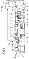
- einen erfindungsgemäßen Bandspeicher in einem schematischen Axialschnitt,
- Fig. 2
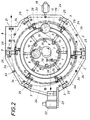
- diesen Bandspeicher in einem achsnormalen Schnitt nach der Linie II-II der Fig. 1,
- Fig. 3
- den Bandspeicher ausschnittsweise in einer Draufsicht im Bereich einer mit einer Schrägrolle zusammenwirkenden Tragrolle des Außenkranzes in einem größeren Maßstab und
- Fig. 4
- die Schrägrolle und die Tragrolle nach der Fig. 3 in einer Seitenansicht.
- Fig. 1
- a tape store according to the invention in a schematic axial section,
- Fig. 2
- this tape storage in an axis-normal section along the line II-II of Fig. 1,
- Fig. 3
- the tape storage in a plan view in the region of a supporting role of the outer ring cooperating with an oblique roller on a larger scale and
- Fig. 4
- the oblique roller and the support roller according to FIG. 3 in a side view.
Der Bandspeicher gemäß dem dargestellten Ausführungsbeispiel besteht im wesentlichen aus einem einen Tisch 1 ringförmig umschließenden Gestell 2, das einen Außenkranz von radial bezüglich der Kranzachse ausgerichteten, angetriebenen Tragrollen 3 zur hochkantigen Aufnahme eines äußeren Bandwickels 4a trägt. Der Tisch 1 weist einen konzentrischen Innenkranz von ebenfalls radial ausgerichteten Tragrollen 5 auf, die frei drehbar gelagert sind und sich von einem Rollenkorb 6 radial nach außen erstrecken, wie dies insbesondere der Fig. 2 entnommen werden kann. Innerhalb des Rollenkorbes 6 ist eine schräggestellte Abzugswalze 7 vorgesehen, der das Band 8 von einer Ablaufrolle 9 zugeführt wird, die eine der Rollen 10 des Rollenkorbes 6 bildet.The tape storage device according to the exemplary embodiment shown essentially consists of a
Zwischen den beiden Kränzen von Tragrollen 3 und 5 ist eine Umlenkrolle 11 vorgesehen, die an einem Arm 12 eines Drehkranzes 13 frei drehbar gelagert ist und mit diesem Drehkranz 13 um den Tisch 1 gedreht werden kann. Zu diesem Zweck ist der am Tisch 1 drehbar gelagerte Drehkranz 13 mit einem Zahnkranz 14 versehen, der mit einem Ritzel 15 kämmt. Zum Antrieb des Ritzels 15 ist ein über eine Gelenkwelle 16 an ein Getriebe 17 angeschlossener Motor 18 vorgesehen, so daß mit Hilfe der Umlenkrolle 11 zwischen dem äußeren Bandwickel 4a und einem inneren Bandwickel 4b, der auf den Rollenkorb 6 aufgewickelt wird und sich hochkant auf den Tragrollen 5 des Innenkranzes abstützt, eine Umlenkschleife 19 gezogen werden kann, zu deren Abstützung eine Stützrolle 20 auf dem Arm 12 für die Umlenkrolle 11 gelagert ist.Between the two rings of
Das über einen aus einem Rollenpaar gebildeten Bandzulauf 21 dem Bandspeicher zulaufende Band 8 gelangt auf die Tragrollen 3 des Außenkranzes, die gemäß der Fig. 1 von einem Motor 22 unter Zwischenschaltung eines entsprechenden Getriebes 23 über Gelenkwellen 24 und Winkeltriebe 25 angetrieben werden. Die Bandförderung über die angetriebenen Tragrollen 3 des Außenkranzes bewirkt, daß das in den Bandspeicher einlaufende Band zu einem Bandwickel 4a auf den Tragrollen 3 aufgewickelt wird. Um die Lage dieses Bandwickels 4a konstruktiv festlegen zu können, ist dem Außenkranz der Tragrollen 3 auf der Innenseite ein Kranz von Schrägrollen 26 zugeordnet, die gemäß dem Ausführungsbeispiel einerseits gegen die Kranzachse hin ansteigen (Fig. 4) und anderseits gegenüber einer radialen Ausrichtung zur Kranzachse gegensinnig zur Umlaufrichtung des Bandes 8 im Bereich des äußeren Bandwickels 4a geneigt verlaufen (Fig. 3). Diese Schrägrollen drängen die in ihren Bereich gelangenden Innenwindungen des Bandwickels 4a radial nach außen, wodurch sich zwischen den radial nach außen drängenden Innenwindungen und den radial einwärts drängenden Außenwindungen ein die Lage des Bandwickels 4a stabilisierendes Gleichgewicht einstellt. Zur Führung der innersten Windung des Bandwickels 4a kann außerdem ein Anlaufbund 27 am inneren Ende der Schrägrollen vorgesehen sein. Werden die Tragrollen 3 des Außenkranzes nach innen abfallend angeordnet, so wird das radiale Einwärtsdrängen der äußeren Bandwindungen unterstützt.The
Von der innersten Windung des äußeren Bandwickels 4a geht das Band in einer Umlenkschleife 19 in den inneren Bandwickel 4b über, der von außen auf den Rollenkorb 6 gewickelt wird, wobei das Band 8 von der innersten Windung über die Ablaufrolle 9 nach innen zur schräggestellten Abzugsrolle 7 verläuft, von der es aus dem Bandspeicher abläuft. Wird das Band 8 lediglich in den Bandspeicher eingespeichert, wird also kein Band aus dem Speicher abgezogen, so läuft die Umlenkrolle 11 mit der halben Bandzulaufgeschwindigkeit um, wobei das Band mit gleichen Windungszahlen auf den inneren und äußeren Bandwickel 4b bzw. 4a gewickelt wird. Bei einer Bandentnahme ohne Bandzulauf bewegt sich die Umlenkrolle 11 gegensinnig zum Aufwickelsinn mit der halben Bandablaufgeschwindigkeit, und es werden sowohl vom äußeren als auch vom inneren Bandwickel die Bandwindungen gleichmäßig abgetragen. Entspricht die Bandzuder Bandablaufgeschwindigkeit, so steht der Antrieb für die Umlenkrolle 11 still. Die Umlaufgeschwindigkeit der Umlenkrolle 11 muß folglich stets der halben Differenz zwischen der Bandzu- und der Bandablaufgeschwindigkeit des Speichers entsprechen. Zu diesem Zweck ist eine Steuereinrichtung 28 vorgesehen, die einerseits an einen Geschwindigkeitsgeber 29 für das in den Bandspeicher einlaufende Band 8 und anderseits an einen Geschwindigkeitsgeber 30 für das aus dem Bandspeicher auslaufende Band angeschlossen ist, wie dies blockschaltbildmäßig in der Fig. 1 angedeutet wird. In Abhängigkeit von der Geschwindigkeitsdifferenz des ein- und auslaufenden Bandes wird der Motor 18 für die Umlenkrolle 11 angesteuert, über die die Umlenkschleife 19 in vorteilhafter Weise gebildet wird, und zwar weitgehend unabhängig von den Größen und Eigenschaften des jeweils eingesetzten Bandes. Damit bei dickeren Bändern 8 eine größere Zugspannung über die Umlenkrolle 11 auf das Band ausgeübt werden kann, um ein flächiges Anliegen der Umlenkschleife 19 am Mantel der Umlenkrolle 11 zu sichern, kann zusätzlich über die Steuereinrichtung 28 der Motor hinsichtlich seines Drehmomentes geregelt werden. Die Banddicke wird über eine Eingabe 31 in die Steuereinrichtung 28 eingegeben, die aufgrund einer vorgegebenen Abhängigkeit zwischen der Banddicke und dem geforderten Drehmoment ein Solldrehmoment vorlegt, das mit dem über einen Drehmomentgeber 32 erfaßten Istdrehmoment verglichen wird, so daß bei einer Soll-Istwertdifferenz ein entsprechender Abgleich stattfinden kann. Über die Eingabe 31 können zusätzliche Einflußgrößen, wie die Breite des zu speichernden Bandes oder Werkstoffeigenschaften, zur Steuerung des Drehmomentes des Motors 18 und damit der wirksamen Zugspannungen im Bereich der Umlenkschleife 19 berücksichtigt werden.From the innermost turn of the
Zur Begrenzung des Außendurchmessers des sich bildenden äußeren Bandwickels 4a ist ein äußerer Rollenkorb 33 vorgesehen, dessen Korbrollen mit 34 bezeichnet sind. Dieser Rollenkorb 33 ist allerdings für die eigentliche Bandspeicherung in zwei gegensinnigen, durch eine Umlenkschleife 19 miteinander verbundenen Bandwickeln 4a und 4b nicht zwingend erforderlich, wie auch die Stützrollen 35 und 36 für das Band im Bereich zwischen der Ablaufrolle 9 und der Abzugsrolle 7 sowie für das auslaufende Band nach der Abzugsrolle unter Umständen entfallen können.To limit the outer diameter of the
Claims (4)
- A strip accumulator, consisting of an outer ring of drivable support rolls (3) disposed radially with respect to the vertical ring axis, for receiving on edge an outer strip coil (4a) with a strip inlet (21) from the exterior, a concentric inner ring of radial support rolls (5) mounted to be freely rotatable for an inner strip coil (4b) connected to the outer strip coil (4a) by a deflector loop (19), and a roll cage (6) forming a winding core for the inner strip coil (4b), one of the axis-parallel rolls (10) of the roll cage guiding the strip (8) in the form of a delivery roll (9) to an inclined take-up roll (7) inside the roll cage (6), characterised in that a deflector roll (11) is provided between the outer and inner rings of the support rolls (3 and 5) for the deflector loop (19), said deflector roll (11) being drivable about the ring axis at a circumferential speed corresponding to half the difference between the strip inlet and strip delivery speed of the accumulator and in that the outer ring of the support rolls (5) has on the inside a ring of inclined rolls (26) which extend so as to slope up radially inwards or so as to slope up radially inwards and at an inclination to a radial orientation relative to the ring axis and in the opposite direction to the direction of rotation of the outer strip coil (4a).
- A strip accumulator according to claim 1, characterised in that the inclined rolls (26) are provided with a guide collar (27) in the region of their inner end.
- A strip accumulator according to claim 1 or 2, characterised in that the support rolls (3) of the outer ring are disposed as to slope downwards and inwards.
- A strip accumulator according to any one of claims 1 to 3, characterised in that a control of the torque in dependence on the thickness and the width of the strip (8) for accumulation can be superimposed on the speed control of the drive for the deflector roll (11).
Applications Claiming Priority (3)
| Application Number | Priority Date | Filing Date | Title |
|---|---|---|---|
| AT1752/93 | 1993-09-01 | ||
| AT0175293A AT401381B (en) | 1993-09-01 | 1993-09-01 | TAPE STORAGE |
| PCT/AT1994/000113 WO1995006528A1 (en) | 1993-09-01 | 1994-08-12 | Belt accumulator |
Publications (2)
| Publication Number | Publication Date |
|---|---|
| EP0666782A1 EP0666782A1 (en) | 1995-08-16 |
| EP0666782B1 true EP0666782B1 (en) | 1997-05-21 |
Family
ID=3520242
Family Applications (1)
| Application Number | Title | Priority Date | Filing Date |
|---|---|---|---|
| EP94922166A Expired - Lifetime EP0666782B1 (en) | 1993-09-01 | 1994-08-12 | Belt accumulator |
Country Status (7)
| Country | Link |
|---|---|
| US (1) | US5575434A (en) |
| EP (1) | EP0666782B1 (en) |
| AT (1) | AT401381B (en) |
| BR (1) | BR9405565A (en) |
| CA (1) | CA2148134C (en) |
| DE (1) | DE59402825D1 (en) |
| WO (1) | WO1995006528A1 (en) |
Families Citing this family (4)
| Publication number | Priority date | Publication date | Assignee | Title |
|---|---|---|---|---|
| WO1997035797A2 (en) * | 1996-03-27 | 1997-10-02 | Oce Printing Systems Gmbh | Device for intermediate storage of a strip-type material |
| FR2751629A1 (en) * | 1996-07-24 | 1998-01-30 | Protection Decoration Conditio | Buffer drum for continued delivery of strip while supply reel is changed e.g. in labelling |
| KR100313474B1 (en) * | 1999-04-13 | 2001-11-15 | 원웅재 | Rotary-Looper |
| KR102369381B1 (en) * | 2019-06-13 | 2022-03-02 | 주식회사 디엠씨 | Vertical strip accumulator |
Family Cites Families (12)
| Publication number | Priority date | Publication date | Assignee | Title |
|---|---|---|---|---|
| US3341139A (en) * | 1966-03-03 | 1967-09-12 | Armco Steel Corp | Apparatus and method for accumulating metallic strip and the like |
| US3782662A (en) * | 1971-02-24 | 1974-01-01 | Armco Steel Corp | Simplified strip accumulation |
| BE792974A (en) * | 1971-12-21 | 1973-04-16 | Tube Prod Ltd | TAPE ACCUMULATOR |
| JPS5220184B2 (en) * | 1973-12-26 | 1977-06-01 | ||
| AT333691B (en) * | 1974-02-22 | 1976-12-10 | Ap Planungsgesellschaft M B H | SPIRAL TAPE STORAGE |
| JPS5717326A (en) * | 1980-07-05 | 1982-01-29 | Nippon Steel Corp | Strip storing equipment |
| AT371743B (en) * | 1981-09-30 | 1983-07-25 | Voest Alpine Ag | BAND STORAGE, IN PARTICULAR FOR TAPE STRIPS |
| US4473193A (en) * | 1983-01-13 | 1984-09-25 | Guild International Inc. | Helical feed-in mechanism for strip accumulator |
| JPS59203045A (en) * | 1983-05-02 | 1984-11-17 | Hitachi Ltd | Looping device for belt-shaped object |
| DE3321786C2 (en) * | 1983-06-16 | 1987-03-19 | Dr. Weusthoff GmbH, 4000 Düsseldorf | Tape storage machine |
| JPS6289527A (en) * | 1985-10-15 | 1987-04-24 | Mitsubishi Heavy Ind Ltd | Strip plate storing device |
| SU1340855A1 (en) * | 1986-03-03 | 1987-09-30 | Старо-Краматорский машиностроительный завод им.Орджоникидзе | Spiral ramp for a strip being rolled |
-
1993
- 1993-09-01 AT AT0175293A patent/AT401381B/en not_active IP Right Cessation
-
1994
- 1994-08-12 WO PCT/AT1994/000113 patent/WO1995006528A1/en active IP Right Grant
- 1994-08-12 BR BR9405565-3A patent/BR9405565A/en not_active Application Discontinuation
- 1994-08-12 EP EP94922166A patent/EP0666782B1/en not_active Expired - Lifetime
- 1994-08-12 US US08/433,419 patent/US5575434A/en not_active Expired - Fee Related
- 1994-08-12 CA CA002148134A patent/CA2148134C/en not_active Expired - Fee Related
- 1994-08-12 DE DE59402825T patent/DE59402825D1/en not_active Expired - Fee Related
Also Published As
| Publication number | Publication date |
|---|---|
| ATA175293A (en) | 1996-01-15 |
| WO1995006528A1 (en) | 1995-03-09 |
| EP0666782A1 (en) | 1995-08-16 |
| US5575434A (en) | 1996-11-19 |
| BR9405565A (en) | 1999-09-08 |
| AT401381B (en) | 1996-08-26 |
| DE59402825D1 (en) | 1997-06-26 |
| CA2148134A1 (en) | 1995-03-09 |
| CA2148134C (en) | 2005-01-04 |
Similar Documents
| Publication | Publication Date | Title |
|---|---|---|
| EP0290731A2 (en) | Storage device | |
| DE2349577C3 (en) | Winding device for the production of cross-wound bobbins | |
| DE1925315A1 (en) | Method and apparatus for treating yarn | |
| DE2262148A1 (en) | METHOD AND DEVICE FOR INTERMEDIATE STORAGE OF TAPE-SHAPED MATERIALS, IN PARTICULAR METAL TAPE, IN CONTINUOUS TAPE FEEDS TO PROCESSING MACHINES | |
| EP0165428A2 (en) | Textile machine with several winding units, whereby a yarn is wound on a conical spool at a constant speed | |
| DE2823718A1 (en) | WINDING DEVICE FOR STRAND-SHAPED GOODS | |
| DE2160867A1 (en) | Winding machine | |
| EP0666782B1 (en) | Belt accumulator | |
| DE2053957C2 (en) | Method for spinning a strand-like product | |
| EP0076245A2 (en) | Strip storage, in particular for sheet-metal strips | |
| EP0652176B1 (en) | Winding device for flexible flat structures as well as method for winding flexible flat structures | |
| DE2820674C2 (en) | Toroidal coil winding device | |
| DE19526445A1 (en) | Decoiler | |
| DE3717295C3 (en) | Method and device for storing continuously delivered strand-like material | |
| DE2619229A1 (en) | WINDING DEVICE FOR YARN OR TAPE | |
| DE3723838C2 (en) | ||
| DE2501832C3 (en) | Machine for winding an incandescent body for an electric incandescent lamp or a discharge tube | |
| CH428518A (en) | Dishwasher | |
| AT227578B (en) | Compensating device for the thread withdrawal of cylindrical bobbins arranged next to one another and driven by the thread withdrawal | |
| DE1088453B (en) | Mounting device on spring winding machines for very long helical springs | |
| DE520210C (en) | Rewinding and cutting machine | |
| EP0239921A1 (en) | Uncoiler device for profile material of bending sensitivity | |
| DE1924503C3 (en) | Coil for strip material | |
| DE19706131C2 (en) | Winding storage | |
| DE19624007A1 (en) | Device for storing of metallic tapes in tape handling plant |
Legal Events
| Date | Code | Title | Description |
|---|---|---|---|
| PUAI | Public reference made under article 153(3) epc to a published international application that has entered the european phase |
Free format text: ORIGINAL CODE: 0009012 |
|
| 17P | Request for examination filed |
Effective date: 19950503 |
|
| AK | Designated contracting states |
Kind code of ref document: A1 Designated state(s): DE FR IT |
|
| GRAG | Despatch of communication of intention to grant |
Free format text: ORIGINAL CODE: EPIDOS AGRA |
|
| GRAH | Despatch of communication of intention to grant a patent |
Free format text: ORIGINAL CODE: EPIDOS IGRA |
|
| 17Q | First examination report despatched |
Effective date: 19961014 |
|
| GRAH | Despatch of communication of intention to grant a patent |
Free format text: ORIGINAL CODE: EPIDOS IGRA |
|
| GRAA | (expected) grant |
Free format text: ORIGINAL CODE: 0009210 |
|
| AK | Designated contracting states |
Kind code of ref document: B1 Designated state(s): DE FR IT |
|
| REF | Corresponds to: |
Ref document number: 59402825 Country of ref document: DE Date of ref document: 19970626 |
|
| ET | Fr: translation filed | ||
| PLBE | No opposition filed within time limit |
Free format text: ORIGINAL CODE: 0009261 |
|
| STAA | Information on the status of an ep patent application or granted ep patent |
Free format text: STATUS: NO OPPOSITION FILED WITHIN TIME LIMIT |
|
| 26N | No opposition filed | ||
| PGFP | Annual fee paid to national office [announced via postgrant information from national office to epo] |
Ref country code: DE Payment date: 20040805 Year of fee payment: 11 |
|
| PGFP | Annual fee paid to national office [announced via postgrant information from national office to epo] |
Ref country code: FR Payment date: 20040809 Year of fee payment: 11 |
|
| PG25 | Lapsed in a contracting state [announced via postgrant information from national office to epo] |
Ref country code: IT Free format text: LAPSE BECAUSE OF NON-PAYMENT OF DUE FEES;WARNING: LAPSES OF ITALIAN PATENTS WITH EFFECTIVE DATE BEFORE 2007 MAY HAVE OCCURRED AT ANY TIME BEFORE 2007. THE CORRECT EFFECTIVE DATE MAY BE DIFFERENT FROM THE ONE RECORDED. Effective date: 20050812 |
|
| PG25 | Lapsed in a contracting state [announced via postgrant information from national office to epo] |
Ref country code: DE Free format text: LAPSE BECAUSE OF NON-PAYMENT OF DUE FEES Effective date: 20060301 |
|
| PG25 | Lapsed in a contracting state [announced via postgrant information from national office to epo] |
Ref country code: FR Free format text: LAPSE BECAUSE OF NON-PAYMENT OF DUE FEES Effective date: 20060428 |
|
| REG | Reference to a national code |
Ref country code: FR Ref legal event code: ST Effective date: 20060428 |