EP0666087B1 - Vorrichtung zum Betreiben einer Feuerlöscheinrichtung - Google Patents
Vorrichtung zum Betreiben einer Feuerlöscheinrichtung Download PDFInfo
- Publication number
- EP0666087B1 EP0666087B1 EP94105109A EP94105109A EP0666087B1 EP 0666087 B1 EP0666087 B1 EP 0666087B1 EP 94105109 A EP94105109 A EP 94105109A EP 94105109 A EP94105109 A EP 94105109A EP 0666087 B1 EP0666087 B1 EP 0666087B1
- Authority
- EP
- European Patent Office
- Prior art keywords
- control
- valve
- bottle
- line
- gas
- Prior art date
- Legal status (The legal status is an assumption and is not a legal conclusion. Google has not performed a legal analysis and makes no representation as to the accuracy of the status listed.)
- Expired - Lifetime
Links
- 238000007789 sealing Methods 0.000 claims description 7
- 238000010791 quenching Methods 0.000 claims 4
- 238000011144 upstream manufacturing Methods 0.000 claims 2
- 238000006073 displacement reaction Methods 0.000 claims 1
- 239000007789 gas Substances 0.000 description 34
- 239000003795 chemical substances by application Substances 0.000 description 5
- 238000012217 deletion Methods 0.000 description 4
- 230000037430 deletion Effects 0.000 description 4
- XKRFYHLGVUSROY-UHFFFAOYSA-N Argon Chemical compound [Ar] XKRFYHLGVUSROY-UHFFFAOYSA-N 0.000 description 2
- 229910000831 Steel Inorganic materials 0.000 description 2
- 238000000034 method Methods 0.000 description 2
- 230000035939 shock Effects 0.000 description 2
- 239000010959 steel Substances 0.000 description 2
- 229920004449 Halon® Polymers 0.000 description 1
- 229910052786 argon Inorganic materials 0.000 description 1
- 230000015572 biosynthetic process Effects 0.000 description 1
- BVKZGUZCCUSVTD-UHFFFAOYSA-N carbonic acid Chemical compound OC(O)=O BVKZGUZCCUSVTD-UHFFFAOYSA-N 0.000 description 1
- 230000003111 delayed effect Effects 0.000 description 1
- PXBRQCKWGAHEHS-UHFFFAOYSA-N dichlorodifluoromethane Chemical compound FC(F)(Cl)Cl PXBRQCKWGAHEHS-UHFFFAOYSA-N 0.000 description 1
- 230000001771 impaired effect Effects 0.000 description 1
- 239000007788 liquid Substances 0.000 description 1
- 238000012423 maintenance Methods 0.000 description 1
- 230000011664 signaling Effects 0.000 description 1
Images



Classifications
-
- F—MECHANICAL ENGINEERING; LIGHTING; HEATING; WEAPONS; BLASTING
- F16—ENGINEERING ELEMENTS AND UNITS; GENERAL MEASURES FOR PRODUCING AND MAINTAINING EFFECTIVE FUNCTIONING OF MACHINES OR INSTALLATIONS; THERMAL INSULATION IN GENERAL
- F16K—VALVES; TAPS; COCKS; ACTUATING-FLOATS; DEVICES FOR VENTING OR AERATING
- F16K1/00—Lift valves or globe valves, i.e. cut-off apparatus with closure members having at least a component of their opening and closing motion perpendicular to the closing faces
- F16K1/30—Lift valves or globe valves, i.e. cut-off apparatus with closure members having at least a component of their opening and closing motion perpendicular to the closing faces specially adapted for pressure containers
- F16K1/304—Shut-off valves with additional means
- F16K1/305—Shut-off valves with additional means with valve member and actuator on the same side of the seat
-
- A—HUMAN NECESSITIES
- A62—LIFE-SAVING; FIRE-FIGHTING
- A62C—FIRE-FIGHTING
- A62C35/00—Permanently-installed equipment
- A62C35/02—Permanently-installed equipment with containers for delivering the extinguishing substance
- A62C35/11—Permanently-installed equipment with containers for delivering the extinguishing substance controlled by a signal from the danger zone
- A62C35/13—Permanently-installed equipment with containers for delivering the extinguishing substance controlled by a signal from the danger zone with a finite supply of extinguishing material
-
- A—HUMAN NECESSITIES
- A62—LIFE-SAVING; FIRE-FIGHTING
- A62C—FIRE-FIGHTING
- A62C35/00—Permanently-installed equipment
- A62C35/58—Pipe-line systems
- A62C35/68—Details, e.g. of pipes or valve systems
-
- A—HUMAN NECESSITIES
- A62—LIFE-SAVING; FIRE-FIGHTING
- A62C—FIRE-FIGHTING
- A62C37/00—Control of fire-fighting equipment
- A62C37/36—Control of fire-fighting equipment an actuating signal being generated by a sensor separate from an outlet device
- A62C37/44—Control of fire-fighting equipment an actuating signal being generated by a sensor separate from an outlet device only the sensor being in the danger zone
-
- A—HUMAN NECESSITIES
- A62—LIFE-SAVING; FIRE-FIGHTING
- A62C—FIRE-FIGHTING
- A62C99/00—Subject matter not provided for in other groups of this subclass
- A62C99/0009—Methods of extinguishing or preventing the spread of fire by cooling down or suffocating the flames
- A62C99/0018—Methods of extinguishing or preventing the spread of fire by cooling down or suffocating the flames using gases or vapours that do not support combustion, e.g. steam, carbon dioxide
-
- F—MECHANICAL ENGINEERING; LIGHTING; HEATING; WEAPONS; BLASTING
- F16—ENGINEERING ELEMENTS AND UNITS; GENERAL MEASURES FOR PRODUCING AND MAINTAINING EFFECTIVE FUNCTIONING OF MACHINES OR INSTALLATIONS; THERMAL INSULATION IN GENERAL
- F16K—VALVES; TAPS; COCKS; ACTUATING-FLOATS; DEVICES FOR VENTING OR AERATING
- F16K1/00—Lift valves or globe valves, i.e. cut-off apparatus with closure members having at least a component of their opening and closing motion perpendicular to the closing faces
- F16K1/30—Lift valves or globe valves, i.e. cut-off apparatus with closure members having at least a component of their opening and closing motion perpendicular to the closing faces specially adapted for pressure containers
- F16K1/304—Shut-off valves with additional means
- F16K1/306—Shut-off valves with additional means with a valve member, e.g. stem or shaft, passing through the seat
-
- F—MECHANICAL ENGINEERING; LIGHTING; HEATING; WEAPONS; BLASTING
- F16—ENGINEERING ELEMENTS AND UNITS; GENERAL MEASURES FOR PRODUCING AND MAINTAINING EFFECTIVE FUNCTIONING OF MACHINES OR INSTALLATIONS; THERMAL INSULATION IN GENERAL
- F16K—VALVES; TAPS; COCKS; ACTUATING-FLOATS; DEVICES FOR VENTING OR AERATING
- F16K31/00—Actuating devices; Operating means; Releasing devices
- F16K31/12—Actuating devices; Operating means; Releasing devices actuated by fluid
- F16K31/122—Actuating devices; Operating means; Releasing devices actuated by fluid the fluid acting on a piston
-
- F—MECHANICAL ENGINEERING; LIGHTING; HEATING; WEAPONS; BLASTING
- F17—STORING OR DISTRIBUTING GASES OR LIQUIDS
- F17C—VESSELS FOR CONTAINING OR STORING COMPRESSED, LIQUEFIED OR SOLIDIFIED GASES; FIXED-CAPACITY GAS-HOLDERS; FILLING VESSELS WITH, OR DISCHARGING FROM VESSELS, COMPRESSED, LIQUEFIED, OR SOLIDIFIED GASES
- F17C13/00—Details of vessels or of the filling or discharging of vessels
- F17C13/04—Arrangement or mounting of valves
-
- F—MECHANICAL ENGINEERING; LIGHTING; HEATING; WEAPONS; BLASTING
- F17—STORING OR DISTRIBUTING GASES OR LIQUIDS
- F17C—VESSELS FOR CONTAINING OR STORING COMPRESSED, LIQUEFIED OR SOLIDIFIED GASES; FIXED-CAPACITY GAS-HOLDERS; FILLING VESSELS WITH, OR DISCHARGING FROM VESSELS, COMPRESSED, LIQUEFIED, OR SOLIDIFIED GASES
- F17C2205/00—Vessel construction, in particular mounting arrangements, attachments or identifications means
- F17C2205/01—Mounting arrangements
- F17C2205/0123—Mounting arrangements characterised by number of vessels
- F17C2205/013—Two or more vessels
- F17C2205/0134—Two or more vessels characterised by the presence of fluid connection between vessels
- F17C2205/0146—Two or more vessels characterised by the presence of fluid connection between vessels with details of the manifold
-
- F—MECHANICAL ENGINEERING; LIGHTING; HEATING; WEAPONS; BLASTING
- F17—STORING OR DISTRIBUTING GASES OR LIQUIDS
- F17C—VESSELS FOR CONTAINING OR STORING COMPRESSED, LIQUEFIED OR SOLIDIFIED GASES; FIXED-CAPACITY GAS-HOLDERS; FILLING VESSELS WITH, OR DISCHARGING FROM VESSELS, COMPRESSED, LIQUEFIED, OR SOLIDIFIED GASES
- F17C2205/00—Vessel construction, in particular mounting arrangements, attachments or identifications means
- F17C2205/03—Fluid connections, filters, valves, closure means or other attachments
- F17C2205/0302—Fittings, valves, filters, or components in connection with the gas storage device
- F17C2205/0323—Valves
-
- F—MECHANICAL ENGINEERING; LIGHTING; HEATING; WEAPONS; BLASTING
- F17—STORING OR DISTRIBUTING GASES OR LIQUIDS
- F17C—VESSELS FOR CONTAINING OR STORING COMPRESSED, LIQUEFIED OR SOLIDIFIED GASES; FIXED-CAPACITY GAS-HOLDERS; FILLING VESSELS WITH, OR DISCHARGING FROM VESSELS, COMPRESSED, LIQUEFIED, OR SOLIDIFIED GASES
- F17C2205/00—Vessel construction, in particular mounting arrangements, attachments or identifications means
- F17C2205/03—Fluid connections, filters, valves, closure means or other attachments
- F17C2205/0302—Fittings, valves, filters, or components in connection with the gas storage device
- F17C2205/0382—Constructional details of valves, regulators
-
- F—MECHANICAL ENGINEERING; LIGHTING; HEATING; WEAPONS; BLASTING
- F17—STORING OR DISTRIBUTING GASES OR LIQUIDS
- F17C—VESSELS FOR CONTAINING OR STORING COMPRESSED, LIQUEFIED OR SOLIDIFIED GASES; FIXED-CAPACITY GAS-HOLDERS; FILLING VESSELS WITH, OR DISCHARGING FROM VESSELS, COMPRESSED, LIQUEFIED, OR SOLIDIFIED GASES
- F17C2270/00—Applications
- F17C2270/07—Applications for household use
- F17C2270/0754—Fire extinguishers
Definitions
- the invention relates to a device for operating a fire extinguishing device with a gaseous extinguishing agent, which is stored in several gas bottles or the like.
- Such fire extinguishing devices work with a liquid carbonic acid as an extinguishing agent stored in high-pressure steel bottles and combined into batteries. All steel bottles are equipped with a cylinder valve which is connected to a common one via high pressure hoses Manifold are connected.
- the first bottle in a bottle group is usually one Control and / or pilot bottle, the bottle valve with an electrically controlled shock spring or the like is equipped. Starting from a fire control panel, the shock spring first electrically controlled and thus opens the cylinder valve of the control or Pilot bottle. The content of this bottle flows through the control line to the rest Bottle valves that are opened as a result.
- Suitable gases are also used for such fire extinguishing devices, e.g. Halon, argon, INERGEN.
- the cylinder valves are the Control and / or pilot bottles with a delay device provided that only after a preset Time to open the control or pilot bottle.
- the preamble of claim 1 and claim 2 is based on a device EP-A-0 409 237.
- a solenoid valve which is controlled by a fire alarm center.
- the Fire control panel also controls other solenoid valves, to activate acoustic signaling devices in the event of a trigger.
- a delay element ensures that the control line Delayed valves operated by the multiple gas cylinders be connected to a manifold.
- the invention has for its object a device to operate a fire extinguisher with a to create gaseous extinguishing agents at which the functionality is improved.
- the formation of the piston valve with a cap has the further advantage that no structural Changes the piston valve to the cap for the control valve as a triggering device trained and a trigger device can be connected to the connecting piece and that the connecting piece of the caps for the cylinder valves connected to the branch lines are.
- a pneumatic deceleration device to the control line between the control valve and the first cylinder valve as a control element installed and provided with a warning device.
- an additional Control device for the cylinder valves can be dispensed with.
- control bottle Is the control bottle as a pilot bottle filled with extinguishing gas and into the control line Throttle body with check valve installed, so can be connected to the throttle body Line to be connected to the manifold.
- the throttle between the control valve and the first cylinder valve the contents of the pilot cylinder can be used for the deletion process can be used.
- Starting from the pilot bottle its content is divided into two Streams divided, one for extinguishing and the other for opening the Subsequent bottles is used.
- the throttle body ensures an even application the control line and the bottle valves prevent backflow into the bottles.
- the Throttle device can also be installed behind the last cylinder valve in a control line be. In this arrangement there is a line from the throttle body to the manifold guided. This measure ensures that the gas from the pilot bottle is initially only is used for control and only then for deletion.
- the throttle element can also be designed as a check valve. This then ensures making sure that the gas from the pilot bottle is fully charged to the control line for so long Is available until pressure builds up in the manifold. Only opens the double check valve and releases the gas from the pilot bottle for extinguishing.
- a Another idea of the invention can be seen in the fact that the control bottle as a pilot bottle Extinguishing gas is filled and that a discharge line from the control valve to the manifold and a control line is led from the manifold to the cylinder valves.
- the manifold is provided with at least two chokes. With this configuration, it flows Gas from the pilot bottle directly into the manifold, in which there is then a pressure to open builds up the bottle valves of the subsequent bottles. Secure the throttling points in the manifold the pressure build-up in this line and guarantee a faultless one without control lines Open the bottle valves.
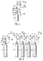
- the fire extinguishing device 1 consists of a battery with the high-pressure gas bottles 2 to 6, 1 bottle 2 with a control gas and the Subsequent bottles 3 to 6 with a high pressure gaseous extinguishing agent are filled.
- the bottle 2 is with a control valve 7 and the following bottles 3 to 6 each with a bottle valve 8 to 11 provided.
- These cylinder valves consist of a direct controlled piston valve, as shown in FIG. 6 or FIG. 8, which has a valve body 46 have, the bottle valves 8 to 11 by means of a cap 27 in the upper region Are completed.
- the control valve 7 has a trigger device 28 instead of the cap 27 in a housing 27a and a known trigger device 17 with undelayed Control device 29b provided.
- the nozzle 25 can also be extended and be provided with an internal thread into which the cap 27 has an external thread is screwed in.
- a piston 48 with a Piston rod 50 which at the lower end with a valve plate 51 and a seal 51a is provided. This lies against a sealing seat 52 of the valve body 46 and goes into one Inner bore 49 via the valve body 46 is by means of a connector 55 with an external thread 56 screwed to the gas bottles 7 to 11.
- a nozzle 53 is in the valve body 46 for Connection of the Control lines provided.
- the piston rod 50 is in the Provide the area of the nozzle 53 with a reduced diameter 54.
- a connecting piece 57 for a pressure measuring device and / or a bypass 58 intended.
- An overflow opening 83 ensures that the control gas flows onto the piston 48.
- a control line 12 goes out, which in Control lines 12a to 12d opens.
- a branch line 13 goes from the control line 12a Port 26 of the cap 27 of the cylinder valve 8.
- the control lines 12b to 12d branch lines 14 to 16 to the connecting piece 26 of the cylinder valves 9 to 11.
- With the Discharge nozzle 53 of the bottle valves 8 to 11 are discharge lines 18 to 21 connected in a manifold 22 open.
- a pneumatic-mechanical Delay device 29 is provided in front of a line 30 with a Warning device 31 is branched.
- the warning device started immediately and the delay device starts to run.
- the control gas flows via lines 12 and 12a to 12 d to the control valves 8 to 11 and opens them so that the extinguishing agent from the gas bottles 3 to 6 in the manifold 22 and from there to the extinguishing lines, not shown can flow.
- a fire alarm center for example, is not shown electrical pulse switched to the electrical trigger device 17 of the control valve 7, the in turn the trigger device 28 and thus the control valve 7 opens. So that flows Extinguishing gas from the control valve 7, to the cylinder valves 8-11.
- the advantage of the piston valve according to the invention can be seen in the fact that a basic valve for multiple valves can be used, e.g. as a pilot bottle valve, as a follower bottle valve or the like. So 27 control or connection heads can be used instead of the cap.
- a throttle element 32 with a kickback protection is in the control line 12 built-in. From the control line 12, the control line 12 a goes to Line 12 b or to line 13 and the other a line 33 to the manifold 22.
- the gas bottle 2 is filled with an extinguishing gas as a pilot bottle, so that this gas can be used for the extinguishing process.
- the throttle element 32 with the kickback protection is equipped so that the extinguishing gas from the pilot bottle in two Streams is divided, which is used for control and deletion become.
- an additional electromechanical delay device 29a intended.
- the throttle element 32a with anti-kickback device is in the last control line 12e provided and via a line 33a with the manifold 22nd connected.
- a branch line is indicated, that of the control line 12 for further controls e.g. is used by range valves.
- a double check valve can be used 70 be installed in the control line 12.
- This double check valve 70 ensures that the gas from the pilot bottle 2 is so long to act on the control line 12 is available until there is a corresponding pressure build-up in the collecting line 22 has stopped. Only then does the double check valve 70 accelerate from pilot bottle 2 free for deletion.
- the double check valve 70 consists of a Valve body 59 with a lower connecting piece 60 for the control gas from line 12 and with an upper discharge nozzle 61 for the line 33 to the manifold 22.
- the Connection piece 60 is assigned a closure body 62 which by means of a spring 63 Closes valve opening 69.
- the closure body 62 sits in a distribution chamber 68 from the several bypass channels 66 go up. These end in radial Overflow channels 67, which in turn are closed by a sealing body 64 with spring 65 being held. After opening the control valve 7, the control gas flows via the line 12 in the socket 60 and thus lifts the closure body 62. The gas flows over the Distribution chamber 68 in the bypass channels 66 and in the overflow channels 67.
- the sealing body 64 holds the discharge nozzle 61 by spring force and gas pressure from below via the bore 71 closed and prevents further flow of the control gas. So that flows Control gas in line 12a and the other lines 12b to 12d and thus opens the Bottle valves 8 to 11.
- Fig. 5 shows a bottle battery without control lines.
- the control valve 7 by means of a Line 38 connected directly to the manifold 22. Branch lines then go from this 39 to 42 to the nozzle 26 of the bottle valves 8 to 11. So that a necessary Control pressure builds up in the manifold 22, a plurality of throttles 43 and 44 are provided.
- FIG. 8 shows a further cylinder valve 8, in which the piston 48 and the piston rod 50 are included a central bore 72 are provided. This is in the area of the piston 48 with a stopper 73 and a seal 74, and with a puncture disk 75 lying between them Mistake.
- the piston rod is above the reduced cross section 54 by a spring 76 and surround an O-ring 77.
- Fig. 9 shows a control valve 7 with a trigger device 28, which has an upper housing 27a and is screwed onto the valve body 46. Sits in an inner bore 78 a needle 79 with which a piercing disk 75 can be opened. The needle 79 is in guided in the lower part in the housing 27a and in the upper part in a plug 80 and further surrounded by an O-ring 81 and a spring 82.
- the invention is not tied to the exemplary embodiments.
- more or less high-pressure gas cylinders (2-6) than shown for an extinguishing battery be summarized.
- the delay devices can also (with appropriate extinguishing gases) 29 with the warning device 31 relating to the exemplary embodiments in FIGS. 2 to 5 belong, or connected to the control valve 7 as delay devices 29a, 29b be.
Landscapes
- Engineering & Computer Science (AREA)
- General Engineering & Computer Science (AREA)
- Mechanical Engineering (AREA)
- Health & Medical Sciences (AREA)
- Public Health (AREA)
- Business, Economics & Management (AREA)
- Emergency Management (AREA)
- Fire-Extinguishing By Fire Departments, And Fire-Extinguishing Equipment And Control Thereof (AREA)
Description
Claims (12)
- Vorrichtung zum Betreiben einer Feuerlöscheinrichtung mit einem gasförmigen Löschmittel, das in mehreren Gasflaschen (3-6) gelagert ist, wobei den Gasflaschen (3-6) eine mit einem Steuergas gefüllte Steuerflasche (2) vorgeschaltet ist, die ein Steuerventil (7) mit einer von einem pneumatischen oder elektrischen Ansteuerimpuls (17) beaufschlagbaren Auslöseeinrichtung (28) aufweist, wobei an das Steuerventil (7) eine Steuerleitung (12) angeschlossen ist, die über Zweigleitungen (13-16;39-42) mit den Flaschenventilen (8-11) der nachfolgenden Gasflaschen (3-6) verbunden ist, und wobei von den Flaschenventilen (8-11) jeweils eine Abführleitung (18-21) zu einer Sammelleitung (22) geführt ist und in die vom Steuerventil (7) ausgehende Steuerleitung (12) eine indirekte pneumatische Verzögerungseinrichtung (29) eingebaut ist,
dadurch gekennzeichnet,daß die Flaschenventile (8-11) und das Steuerventil (7) als Kolbenventil (46) mit einer aufgeschraubten Kappe (27,27a) mit einem Anschlußstutzen (26,26a) ausgebildet sind,daß die Auslöseeinrichtung (28) auf das Steuerventil (7) aufgesetzt ist, unddaß auf die Auslöseeinrichtung (28) eine unverzögerte elektromechanische Steuereinrichtung (29b) aufgesetzt ist. - Vorrichtung zum Betrieben einer Feuerlöscheinrichtung mit einem gasförmigen Löschmittel, das in mehreren Gasflaschen (3-6) gelagert ist, wobei den Gasflaschen (3-6) eine mit einem Steuergas gefüllte Steuerflasche (2) vorgeschaltet ist, die ein Steuerventil (7) mit einer von einem pneumatischen oder elektrischen Ansteuerimpuls (17) beaufschlagbaren Auslöseeinrichtung (28) aufweist, wobei an das Steuerventil (7) eine Steuerleitung (12) angeschlossen ist, die über Zweigleitungen (13-16;39-42) mit den Flaschenventilen (8-11) der nachfolgenden Gasflaschen (3-6) verbunden ist, und wobei von den Flaschenventilen (8-11) jeweils eine Abführleitung (18-21) zu einer Sammelleitung (22) geführt ist,
dadurch gekennzeichnet,daß die Flaschenventile (8-11) und das Steuerventil (7) als Kolbenventil (46) mit einer aufgeschraubten Kappe (27,27a) mit einem Anschlußstutzen (26,26a) ausgebildet sind, die Auslöseeinrichtung (28) auf das Steuerventil (7) aufgesetzt ist, und auf die Auslöseeinrichtung (28) eine direkte elektromechanische Zeit-Verzögerungseinrichtung (29a) aufgesetzt ist. - Vorrichtung nach Anspruch 1 oder 2, dadurch gekennzeichnet, daß die Anschlußstutzen (26,26a) der Kappen (27,27a) für die Flaschenventile (8-11) mit den Zweigleitungen (13-16;39-42) verbunden sind.
- Vorrichtung nach einem der Ansprüche 1-3, dadurch gekennzeichnet, daß die Steuerflasche (2) als Pilotflasche mit Löschgas gefüllt ist, daß von der Steuerleitung (12) Leitungen (12a-12e) zu den Flaschenventilen (8-11) abgezweigt sind, und daß zwischen der ersten Abzweigung und der Sammelleitung (22) innerhalb der Steuerleitung (12) oder hinter dem letzten Flaschenventil (11) ein Drosselorgan (32,32a) mit Rückschlagsicherung eingebaut ist, von dem eine Leitung (33;33a) zur Sammelleitung (22) führt.
- Vorrichtung nach Anspruch 4, dadurch gekennzeichnet, daß das Drosselorgan als Doppel-Rückschlagventil (70) ausgebildet ist.
- Vorrichtung nach einem der Ansprüche 1-5, dadurch gekennzeichnet, daß die Anschlüsse für die Zweigleitungen (13-16) als T-Stücke ausgebildet sind, wobei die Steuerleitung (12) zwischen den einzelnen Anschlüssen aus Schläuchen bestehen, die auf die Enden der T-Stücke aufgesteckt sind.
- Vorrichtung nach Anspruch 1 oder 2, dadurch gekennzeichnet, daß die Steuerflasche (2) als Pilotflasche mit Löschgas gefüllt ist, daß von dem Steuerventil (7) eine Abführleitung (38) mit einer Rückschlagsicherung (45) zu der Sammelleitung (22) und von dieser jeweils eine Zweigleitung (39-42) zu den Flaschenventilen (8-11) geführt sind, und daß die Sammelleitung (22) mit mindestens zwei Drosseln (43,44) versehen ist.
- Vorrichtung nach einem der Ansprüche 1-7, dadurch gekennzeichnet, daß die Abführleitungen (18-21) mit Rückschlagsicherungen (34-37) versehen sind,
- Vorrichtung nach einem der Ansprüche 1-8, bei welcher das Kolbenventil (46) einen Ventilkörper mit Innenbohrung (49) und einen Gewindestutzen (55) zum Aufschrauben auf die Steuer- und Gasflaschen (2-6) sowie einen Anschlußstutzen (26) für das Steuergas und einen Abfuhrstutzen (53) für das Steuer- bzw. Löschgas sowie einen in der Bohrung (47) des Ventilkörpers bewegbaren Steuerkolben (48) aufweist, dadurch gekennzeichnet, daß das Kolbenventil (46) eine Kolbenstange (50) aufweist, die am unteren Ende eine Ventilplatte (51a) trägt, die vom Steuer- bzw. Löschgas gegen einen Ventilsitz (52) des Ventilkörpers (46) preßbar ist, und daß die Kolbenstange (50) im Bereich des Abfuhrstutzens (53) einen verringerten Querschnitt (54) aufweist.
- Vorrichtung nach Anspruch 9, dadurch gekennzeichnet, daß in den Ventilkörper unterhalb der Ventilplatte (51a) seitlich ein Anschlußstutzen (57) für ein Druckmeßgerät und/oder eine Bypassleitung (58) und etwa auf gleicher Ebene versetzt dazu ein Anschlußstutzen (57a) für eine Berstscheibe (57b) o.dgl. vorgesehen sind.
- Vorrichtung nach Anspruch 5, dadurch gekennzeichnet, daß das Doppel-Rückschlagventil (70) einen Ventilkörper (59) mit Anschluß- (60) und Abfuhrstutzen (61), einen unteren Verschlußkörper (62) mit Feder (63) und einen oberen Dichtkörper (64) mit Feder (65) aufweist, und daß Bypasskanäle (66) mit unterer Verteilerkammer (68) und oberen Überströmkanälen (67) vorgesehen sind, die bei geschlossener Gasflasche mittels der Federn (63,65) vom Verschlußkörper (62) bzw. Dichtkörper (64) nach außen abgedichtet sind.
- Vorrichtung nach Anspruch 11, dadurch gekennzeichnet, daß der Dichtkörper (64) mit einem oberen Durchmesser D und einem unteren Durchmesser d ausgebildet ist, wobei D > d ist.
Applications Claiming Priority (2)
| Application Number | Priority Date | Filing Date | Title |
|---|---|---|---|
| DE4402396 | 1994-01-27 | ||
| DE4402396A DE4402396C2 (de) | 1993-02-12 | 1994-01-27 | Vorrichtung zum Betreiben einer Feuerlöscheinrichtung |
Publications (2)
| Publication Number | Publication Date |
|---|---|
| EP0666087A1 EP0666087A1 (de) | 1995-08-09 |
| EP0666087B1 true EP0666087B1 (de) | 1999-09-22 |
Family
ID=6508823
Family Applications (1)
| Application Number | Title | Priority Date | Filing Date |
|---|---|---|---|
| EP94105109A Expired - Lifetime EP0666087B1 (de) | 1994-01-27 | 1994-03-31 | Vorrichtung zum Betreiben einer Feuerlöscheinrichtung |
Country Status (2)
| Country | Link |
|---|---|
| EP (1) | EP0666087B1 (de) |
| AT (1) | ATE184801T1 (de) |
Families Citing this family (11)
| Publication number | Priority date | Publication date | Assignee | Title |
|---|---|---|---|---|
| DE20000365U1 (de) * | 2000-01-11 | 2001-05-23 | TOTAL WALTHER GmbH, Feuerschutz und Sicherheit, 51069 Köln | Gas-Hochdruck-Feuerlöschanlage |
| US6390158B2 (en) * | 2000-04-21 | 2002-05-21 | Superior Products, Inc. | Post valve yoke |
| ES2247292T3 (es) * | 2002-05-17 | 2006-03-01 | Vesta Srl | Valvula de descarga rapida para un sistema de extincion de incendios de gas inerte a alta presion. |
| EP1872039B1 (de) * | 2005-04-07 | 2014-01-29 | Chubb International Holdings Limited | Druckluftstromregelventil zur brandunterdrückungsüberdruckverhinderung |
| GB0806530D0 (en) | 2008-04-10 | 2008-05-14 | Boc Group Plc | Tamper-resistant valve and connection arrangement |
| DE102010028858A1 (de) | 2010-05-11 | 2011-11-17 | Fiwarec Valves & Regulators Gmbh & Co. Kg | Ventil |
| DE102013010167B4 (de) | 2013-06-19 | 2023-07-20 | Fogtec Brandschutz Gmbh | Ventilsystem |
| DE102016205772B4 (de) | 2016-04-07 | 2017-11-30 | Minimax Gmbh & Co. Kg | Schnellöffnungsventil für einen druckbeaufschlagten Löschfluidbehälter und Löschfluidbehälter mit selbigem |
| AT519754B1 (de) * | 2017-06-23 | 2018-10-15 | Accuro Sonderloeschanlagen Gmbh | Hauptsteuerventil für eine Feuerlöschanlage |
| DE102020103155A1 (de) * | 2020-02-07 | 2021-08-12 | Bayerische Motoren Werke Aktiengesellschaft | Druckbehälteranordnung und Druckbehältersystem |
| CN114602109A (zh) * | 2020-12-04 | 2022-06-10 | 西安核设备有限公司 | 一种机/电双延时装置 |
Citations (1)
| Publication number | Priority date | Publication date | Assignee | Title |
|---|---|---|---|---|
| EP0615771A1 (de) * | 1993-02-12 | 1994-09-21 | Total Walther Feuerschutz GmbH | Vorrichtung zum Betreiben einer Feuerlöscheinrichtung |
Family Cites Families (4)
| Publication number | Priority date | Publication date | Assignee | Title |
|---|---|---|---|---|
| FR1330001A (fr) * | 1962-07-26 | 1963-06-14 | Dispositif de commande à distance par fluides, d'extincteurs d'incendie | |
| FR2437553A1 (fr) * | 1978-09-27 | 1980-04-25 | Cerberus Guinard | Vanne a ouverture automatique, notamment pour des installations de protection contre l'incendie |
| DE3915435A1 (de) * | 1989-05-11 | 1990-11-15 | Total Feuerschutz Gmbh | Verfahren zum betreiben einer feuerloeschanlage |
| DE3923935A1 (de) * | 1989-07-19 | 1991-01-24 | Hekatron Gmbh | Feuerloeschanlage fuer gasfoermige loeschmittel |
-
1994
- 1994-03-31 AT AT94105109T patent/ATE184801T1/de active
- 1994-03-31 EP EP94105109A patent/EP0666087B1/de not_active Expired - Lifetime
Patent Citations (1)
| Publication number | Priority date | Publication date | Assignee | Title |
|---|---|---|---|---|
| EP0615771A1 (de) * | 1993-02-12 | 1994-09-21 | Total Walther Feuerschutz GmbH | Vorrichtung zum Betreiben einer Feuerlöscheinrichtung |
Also Published As
| Publication number | Publication date |
|---|---|
| EP0666087A1 (de) | 1995-08-09 |
| ATE184801T1 (de) | 1999-10-15 |
Similar Documents
| Publication | Publication Date | Title |
|---|---|---|
| EP1224014B1 (de) | Vorrichtung zum löschen eines feuers | |
| EP2569058A1 (de) | Ventil | |
| EP0666087A1 (de) | Vorrichtung zum Betreiben einer Feuerlöscheinrichtung | |
| EP0615771B1 (de) | Vorrichtung zum Betreiben einer Feuerlöscheinrichtung | |
| DE3422023C2 (de) | Lungenautomat für Atemschutzgerät | |
| DE1952121C3 (de) | Warnsignalvorrichtung für Atemschutzgeräte mit Druckgasvorrat | |
| DE19601777A1 (de) | Stationäre Feuerlöschanlage | |
| DE2731804C3 (de) | Sicherheitseinrichtung für Tanks für verflüssigtes Gas | |
| EP0004595B1 (de) | Steuerbares Ventil für eine Brandlöschanlage | |
| DE102021134603A1 (de) | Auslösevorrichtung für eine Feuerlöschanordnung | |
| DE2233144A1 (de) | Vorrichtung zur absperrung beschaedigter sektoren einer pneumatischen, mehrere sektoren aufweisenenden bremsanlage von kraftfahrzeugen | |
| EP1452652A2 (de) | Ventilanordnung für einen Rohrtrenner | |
| EP1116499B1 (de) | Gas-Hochdruck-Feuerlöschanlage | |
| EP1260248B1 (de) | Verfahren und Vorrichtung zur Steuerung einer Gas-Hochdruck-Feuerlöschanlage | |
| DE3333234C2 (de) | Schlauchbruchsicherung mit Leckgasüberprüfungseinrichtung | |
| DE10156284B4 (de) | Absperrarmatur für einen Strömungswächter | |
| EP0246617A2 (de) | Luftstossgerät zur Auflösung von Materialsaufstauungen in Lagersilos für Schüttgut | |
| DE102011005286B4 (de) | Verfahren zum Betreiben einer Brennkraftmaschine und Brennkraftmaschine | |
| DE855317C (de) | Narkosegeraet | |
| DE2840191A1 (de) | Sicherheitseinrichtung fuer tanks fuer verfluessigtes gas | |
| DE9404892U1 (de) | Blasvorrichtung zum stoßartigen Ausblasen von Luft | |
| DE202024105811U1 (de) | Automatisches Ventil für Brandbekämpfungs- und Brandunterdrückungssysteme | |
| CH366750A (de) | Druckgasatemschutzgerät mit einem federbelasteten, als Warnsignalvorrichtung dienenden Rückschlagventil | |
| DE1600937C3 (de) | Gasflaschenventil für aufsteckbare Membrandruckregler | |
| DE2911814A1 (de) | Leckgassicherung fuer eine schlauchleitung |
Legal Events
| Date | Code | Title | Description |
|---|---|---|---|
| PUAI | Public reference made under article 153(3) epc to a published international application that has entered the european phase |
Free format text: ORIGINAL CODE: 0009012 |
|
| 17P | Request for examination filed |
Effective date: 19940331 |
|
| AK | Designated contracting states |
Kind code of ref document: A1 Designated state(s): AT BE CH DE DK ES FR GB IT LI NL SE |
|
| 17Q | First examination report despatched |
Effective date: 19961010 |
|
| RAP1 | Party data changed (applicant data changed or rights of an application transferred) |
Owner name: TOTAL WALTHER GMBH, FEUERSCHUTZ UND SICHERHEIT |
|
| GRAG | Despatch of communication of intention to grant |
Free format text: ORIGINAL CODE: EPIDOS AGRA |
|
| GRAG | Despatch of communication of intention to grant |
Free format text: ORIGINAL CODE: EPIDOS AGRA |
|
| GRAH | Despatch of communication of intention to grant a patent |
Free format text: ORIGINAL CODE: EPIDOS IGRA |
|
| GRAH | Despatch of communication of intention to grant a patent |
Free format text: ORIGINAL CODE: EPIDOS IGRA |
|
| GRAA | (expected) grant |
Free format text: ORIGINAL CODE: 0009210 |
|
| AK | Designated contracting states |
Kind code of ref document: B1 Designated state(s): AT BE CH DE DK ES FR GB IT LI NL SE |
|
| PG25 | Lapsed in a contracting state [announced via postgrant information from national office to epo] |
Ref country code: SE Free format text: THE PATENT HAS BEEN ANNULLED BY A DECISION OF A NATIONAL AUTHORITY Effective date: 19990922 Ref country code: IT Free format text: LAPSE BECAUSE OF FAILURE TO SUBMIT A TRANSLATION OF THE DESCRIPTION OR TO PAY THE FEE WITHIN THE PRE;WARNING: LAPSES OF ITALIAN PATENTS WITH EFFECTIVE DATE BEFORE 2007 MAY HAVE OCCURRED AT ANY TIME BEFORE 2007. THE CORRECT EFFECTIVE DATE MAY BE DIFFERENT FROM THE ONE RECORDED.SCRIBED TIME-LIMIT Effective date: 19990922 Ref country code: GB Free format text: LAPSE BECAUSE OF FAILURE TO SUBMIT A TRANSLATION OF THE DESCRIPTION OR TO PAY THE FEE WITHIN THE PRESCRIBED TIME-LIMIT Effective date: 19990922 Ref country code: FR Free format text: LAPSE BECAUSE OF FAILURE TO SUBMIT A TRANSLATION OF THE DESCRIPTION OR TO PAY THE FEE WITHIN THE PRESCRIBED TIME-LIMIT Effective date: 19990922 Ref country code: ES Free format text: THE PATENT HAS BEEN ANNULLED BY A DECISION OF A NATIONAL AUTHORITY Effective date: 19990922 |
|
| REF | Corresponds to: |
Ref document number: 184801 Country of ref document: AT Date of ref document: 19991015 Kind code of ref document: T |
|
| REG | Reference to a national code |
Ref country code: CH Ref legal event code: NV Representative=s name: TROESCH SCHEIDEGGER WERNER AG Ref country code: CH Ref legal event code: EP |
|
| REF | Corresponds to: |
Ref document number: 59408769 Country of ref document: DE Date of ref document: 19991028 |
|
| PG25 | Lapsed in a contracting state [announced via postgrant information from national office to epo] |
Ref country code: DK Free format text: LAPSE BECAUSE OF FAILURE TO SUBMIT A TRANSLATION OF THE DESCRIPTION OR TO PAY THE FEE WITHIN THE PRESCRIBED TIME-LIMIT Effective date: 19991222 |
|
| EN | Fr: translation not filed | ||
| GBV | Gb: ep patent (uk) treated as always having been void in accordance with gb section 77(7)/1977 [no translation filed] |
Effective date: 19990922 |
|
| PLBE | No opposition filed within time limit |
Free format text: ORIGINAL CODE: 0009261 |
|
| STAA | Information on the status of an ep patent application or granted ep patent |
Free format text: STATUS: NO OPPOSITION FILED WITHIN TIME LIMIT |
|
| 26N | No opposition filed | ||
| PGFP | Annual fee paid to national office [announced via postgrant information from national office to epo] |
Ref country code: CH Payment date: 20130325 Year of fee payment: 20 Ref country code: DE Payment date: 20130327 Year of fee payment: 20 |
|
| PGFP | Annual fee paid to national office [announced via postgrant information from national office to epo] |
Ref country code: AT Payment date: 20130305 Year of fee payment: 20 |
|
| PGFP | Annual fee paid to national office [announced via postgrant information from national office to epo] |
Ref country code: BE Payment date: 20130327 Year of fee payment: 20 |
|
| PGFP | Annual fee paid to national office [announced via postgrant information from national office to epo] |
Ref country code: NL Payment date: 20130326 Year of fee payment: 20 |
|
| BE20 | Be: patent expired |
Owner name: *TOTAL WALTHER G.M.B.H. FEUERSCHUTZ UND SICHERHEIT Effective date: 20140331 |
|
| REG | Reference to a national code |
Ref country code: NL Ref legal event code: V4 Effective date: 20140331 Ref country code: DE Ref legal event code: R071 Ref document number: 59408769 Country of ref document: DE |
|
| REG | Reference to a national code |
Ref country code: CH Ref legal event code: PL |
|
| REG | Reference to a national code |
Ref country code: AT Ref legal event code: MK07 Ref document number: 184801 Country of ref document: AT Kind code of ref document: T Effective date: 20140331 |
|
| PG25 | Lapsed in a contracting state [announced via postgrant information from national office to epo] |
Ref country code: DE Free format text: LAPSE BECAUSE OF EXPIRATION OF PROTECTION Effective date: 20140401 |