EP0666014B1 - Fahrbares Bodenlockerungsgerät - Google Patents
Fahrbares Bodenlockerungsgerät Download PDFInfo
- Publication number
- EP0666014B1 EP0666014B1 EP95101299A EP95101299A EP0666014B1 EP 0666014 B1 EP0666014 B1 EP 0666014B1 EP 95101299 A EP95101299 A EP 95101299A EP 95101299 A EP95101299 A EP 95101299A EP 0666014 B1 EP0666014 B1 EP 0666014B1
- Authority
- EP
- European Patent Office
- Prior art keywords
- tool
- implement according
- mobile soil
- loosening
- travel
- Prior art date
- Legal status (The legal status is an assumption and is not a legal conclusion. Google has not performed a legal analysis and makes no representation as to the accuracy of the status listed.)
- Expired - Lifetime
Links
- 239000002689 soil Substances 0.000 title description 14
- 230000001360 synchronised effect Effects 0.000 claims description 2
- 238000010276 construction Methods 0.000 claims 1
- 238000005056 compaction Methods 0.000 description 3
- 230000035515 penetration Effects 0.000 description 3
- 230000000149 penetrating effect Effects 0.000 description 2
- 239000000969 carrier Substances 0.000 description 1
- 230000000694 effects Effects 0.000 description 1
- 238000003780 insertion Methods 0.000 description 1
- 230000037431 insertion Effects 0.000 description 1
- 230000010355 oscillation Effects 0.000 description 1
- 239000000725 suspension Substances 0.000 description 1
Images

Classifications
-
- A—HUMAN NECESSITIES
- A01—AGRICULTURE; FORESTRY; ANIMAL HUSBANDRY; HUNTING; TRAPPING; FISHING
- A01B—SOIL WORKING IN AGRICULTURE OR FORESTRY; PARTS, DETAILS, OR ACCESSORIES OF AGRICULTURAL MACHINES OR IMPLEMENTS, IN GENERAL
- A01B45/00—Machines for treating meadows or lawns, e.g. for sports grounds
- A01B45/02—Machines for treating meadows or lawns, e.g. for sports grounds for aerating
- A01B45/023—Perforators comprising spiking tools actively driven in a reciprocating movement through a crankshaft or eccentric mechanism
-
- A—HUMAN NECESSITIES
- A01—AGRICULTURE; FORESTRY; ANIMAL HUSBANDRY; HUNTING; TRAPPING; FISHING
- A01B—SOIL WORKING IN AGRICULTURE OR FORESTRY; PARTS, DETAILS, OR ACCESSORIES OF AGRICULTURAL MACHINES OR IMPLEMENTS, IN GENERAL
- A01B11/00—Ploughs with oscillating, digging or piercing tools driven or not
Definitions
- the invention relates to a mobile soil loosening device, in which on a frame which can be attached to the tractor, a plurality of swiveling tool swings about a horizontal axis extending transversely to the direction of travel are mounted, which carry tool chisels and in which the tool swings via a drive shaft about their swivel bearing are moving up and down.
- Such soil loosening devices are used, for example, for working on sports fields, where heavily hardened areas alternate with softer, unplayed areas, and a uniform soil texture is to be produced by uniform loosening of the soil, which can be followed by compaction using suitable rollers.
- a generic soil loosening device is shown in DE-A-3404675.
- a similar soil loosening device is known from EP-A-0 092 201.
- the rear lever arm of the double-armed tool rocker carries a tool carrier bar which carries the tools designed as chisels next to one another at predetermined intervals, so that all tools are moved up and down simultaneously.
- the tools are automatically adapted to a changing degree of compaction of the soil and a uniform loosening effect is brought about by the fact that the oscillation amplitude of the tool rocker is automatically set according to the degree of compaction.
- each tool chisel is assigned a disk coulter, which is also connected to the tool rocker and penetrates into the ground in front of and above the chisel in the direction of movement.
- a continuous up and down movement of the tools is not provided here.
- the invention has for its object to further improve a generic soil loosening device, in particular for working on sports fields, in such a way that, with a simple, constructive structure, a flat loosening of the base layer or of the soil under a lawn area is ensured without the turf sod being destroyed thereby.
- the tool carriers are stored flexibly via rubber bearings, which means that the turning and unscrewing movement is maintenance-free.
- the tool carrier with the tools attached to it can thereby move sideways to avoid jamming on foreign bodies that are in and under the turf.
- the moving parts are symmetrical, so that dynamic unbalances cannot form and the device can work without vibration even at high stroke rates.
- the support frame is supported by a support frame that can be rolled on the floor via a chassis that consists of a front smooth roller (in front of the tools) and a rear grid roller in the direction of travel behind the tools. Through these rollers the set penetration depth of the tools is maintained regardless of the towing vehicle.
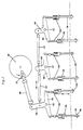
- Fig. 1 only the tool arms arranged in the direction of travel on the left side u. Like. visible; in connection with Fig. 2, however, it can be seen that several work groups are arranged side by side, the number and arrangement of which determines the overall machine width.
- a support frame 14 of the soil loosening device is suspended on the two lower struts 10 and the upper lifting strut 12 of a three-point suspension of a tractor.
- This support frame has rearward-facing struts 14a, which carry an inverted U-shaped frame part 14b, which extends transversely to the direction of travel, and on the top in the middle part carries bearings 16 for the rear end of the drive shaft 18 of the tractor.
- the rear end of the propeller shaft 18 carries a crank disk 20 with a radially adjustable crank pin 22 which, as will be described below, serves as a drive for the tools.
- the support frame 14 is rigidly but vertically supported by a support frame 24 via pins 26. According to the exemplary embodiment shown, a plurality of insertion holes are provided for the pins 26 in order to bring about the height adjustability. Of course, other adjusting means, for example threaded spindles or the like, can also be provided for this purpose.
- This support frame has front and rear, downward-pointing arms that are supported on a chassis. This undercarriage consists of a front smooth roller 28 which lies in front of the tools in the direction of travel and a rear grid roller 30 which is behind the tools in the direction of travel.
- the front, downward-pointing leg of the support frame 14b carries at the lower end a pivot bearing 32 on which a plurality of tool rockers 34 are articulated with their front end.
- These tool rockers carry coulter discs 36 penetrating the ground in the middle section and tools 38 penetrating the ground at the rear end in the form of chisels, on the side surfaces of which loosening wings 40 are attached.
- the support frame 14b supports several double angle levers 44 on its rear side via pivot 42.
- the center arm 46 of the double angle lever located on the left in FIG. 2 is pivotally connected to a link 48 which in turn is connected to the crankpin 22 of the crank disk (20) is articulated.
- Drive links 50 are articulated on the two laterally extending arms of the double angle lever 44, which in turn are connected in pairs to tool rockers 34 via rubber bearings.
- the middle arms 46 of the double angle levers 44 are connected via connecting links 52, as a result of which a synchronous movement of the individual tool pairs takes place.
- the coulter discs 36 and the tool chisel 38 are moved over the tool rockers 34 by the crank mechanism 20, 22 and the double angle lever 44 and the drive link 50 in a periodically up and down movement, the tools of a pair, as shown in FIG. 2, are controlled in opposite directions in their lifting movement.
- the penetration depth of the tools can be changed on the one hand by the height adjustability between the frames 14 and 24 and also by adjusting the eccentricity of the crank mechanism 20, 22.
- the slightly arched grooves formed by the coulter discs 36 and the chisel 38 are closed by the trailing grating roller 30, so that a loosened but smooth covering layer is formed.
- the set smooth penetration depth of the tools is maintained by the front smooth roller 28 of the undercarriage regardless of the towing vehicle. Due to the loosening wings 40 attached to the side of the chisels 38, the sod is alternately raised and lowered via the paired arrangement of the tools. Due to the floating attachment to the towing vehicle and the chassis of the support frame 24, no loads are transmitted to the rear wheels of the towing vehicle.
- FIG. 1 Although only one side frame part can be seen in each case in FIG. 1, it follows from the overall context that the frame arrangement and storage take place on at least two sides adjacent to the roller ends, and the frame arrangement naturally also extends transversely to the direction of travel, which in FIG. 2 is not shown for clarity.
Landscapes
- Life Sciences & Earth Sciences (AREA)
- Engineering & Computer Science (AREA)
- Mechanical Engineering (AREA)
- Soil Sciences (AREA)
- Environmental Sciences (AREA)
- Soil Working Implements (AREA)
- Agricultural Machines (AREA)
- Body Structure For Vehicles (AREA)
- Catching Or Destruction (AREA)
Applications Claiming Priority (2)
| Application Number | Priority Date | Filing Date | Title |
|---|---|---|---|
| DE4403158A DE4403158C1 (de) | 1994-02-02 | 1994-02-02 | Fahrbares Bodenlockerungsgerät |
| DE4403158 | 1994-02-02 |
Publications (2)
| Publication Number | Publication Date |
|---|---|
| EP0666014A1 EP0666014A1 (de) | 1995-08-09 |
| EP0666014B1 true EP0666014B1 (de) | 1997-06-04 |
Family
ID=6509286
Family Applications (1)
| Application Number | Title | Priority Date | Filing Date |
|---|---|---|---|
| EP95101299A Expired - Lifetime EP0666014B1 (de) | 1994-02-02 | 1995-01-31 | Fahrbares Bodenlockerungsgerät |
Country Status (7)
| Country | Link |
|---|---|
| EP (1) | EP0666014B1 (pl) |
| AT (1) | ATE153823T1 (pl) |
| CZ (1) | CZ288505B6 (pl) |
| DE (2) | DE4403158C1 (pl) |
| ES (1) | ES2103612T3 (pl) |
| PL (1) | PL175501B1 (pl) |
| SK (1) | SK281978B6 (pl) |
Families Citing this family (3)
| Publication number | Priority date | Publication date | Assignee | Title |
|---|---|---|---|---|
| CN105210480A (zh) * | 2015-10-24 | 2016-01-06 | 中山市奥斯精工机械科技有限公司 | 一种轻便式多用农耕机 |
| IT201700054482A1 (it) * | 2017-05-19 | 2018-11-19 | Gramegna Srl | Macchina agricola per decompattare ed arieggiare il terreno. |
| CN111771433A (zh) * | 2020-08-28 | 2020-10-16 | 张静 | 一种用于种植浆果的翻土设备 |
Family Cites Families (6)
| Publication number | Priority date | Publication date | Assignee | Title |
|---|---|---|---|---|
| US3627056A (en) * | 1968-12-23 | 1971-12-14 | Thelmer A Rogers | Vibrating plow with balanced forces |
| GB1306212A (pl) * | 1969-06-12 | 1973-02-07 | ||
| US4102402A (en) * | 1976-09-13 | 1978-07-25 | Vibra-King, Inc. | Subsoiler |
| US4245705A (en) * | 1979-04-07 | 1981-01-20 | Kubota, Ltd. | Apparatus for taking off vibratory power for tractor |
| EP0092201B1 (de) * | 1982-04-16 | 1986-03-19 | Wolf-Geräte GmbH | Fahrbares Bodenlockerungsgerät |
| DE3404675A1 (de) * | 1984-02-10 | 1985-08-14 | Alfred Dr.-Ing. 7900 Ulm Eggenmüller | Bodenbearbeitungsgeraet mit schwingenden scharen und einer fraesmesserwalze |
-
1994
- 1994-02-02 DE DE4403158A patent/DE4403158C1/de not_active Expired - Fee Related
-
1995
- 1995-01-30 CZ CZ1995228A patent/CZ288505B6/cs unknown
- 1995-01-31 ES ES95101299T patent/ES2103612T3/es not_active Expired - Lifetime
- 1995-01-31 DE DE59500271T patent/DE59500271D1/de not_active Expired - Lifetime
- 1995-01-31 AT AT95101299T patent/ATE153823T1/de not_active IP Right Cessation
- 1995-01-31 EP EP95101299A patent/EP0666014B1/de not_active Expired - Lifetime
- 1995-02-01 PL PL95307020A patent/PL175501B1/pl not_active IP Right Cessation
- 1995-02-02 SK SK133-95A patent/SK281978B6/sk unknown
Also Published As
| Publication number | Publication date |
|---|---|
| ES2103612T3 (es) | 1997-09-16 |
| CZ22895A3 (en) | 1995-08-16 |
| PL175501B1 (pl) | 1999-01-29 |
| ATE153823T1 (de) | 1997-06-15 |
| CZ288505B6 (cs) | 2001-07-11 |
| PL307020A1 (en) | 1995-08-07 |
| SK281978B6 (sk) | 2001-09-11 |
| DE4403158C1 (de) | 1995-04-27 |
| DE59500271D1 (de) | 1997-07-10 |
| SK13395A3 (en) | 1995-08-09 |
| EP0666014A1 (de) | 1995-08-09 |
Similar Documents
| Publication | Publication Date | Title |
|---|---|---|
| EP2605632B1 (de) | Gezogene landwirtschaftliche maschine mit packereinheit und verfahren zur handhabung einer solchen maschine | |
| DE3930811B4 (de) | Vorrichtung zur Bodenanpassung der Arbeitswerkzeuge von Heumaschinen | |
| DE60037458T2 (de) | Landwirtschaftliches Gerät | |
| DE3128709C2 (pl) | ||
| DE2053073B2 (de) | Mähmaschine | |
| DE1965793A1 (de) | Kombinierte Rasenschneide- und -kehrmaschine | |
| DE3004576A1 (de) | Kombinatsgeraet zur bodenbearbeitung | |
| DE60319573T2 (de) | Bodenbearbeitungseinheit mit abgewinkelten scheiben | |
| DE19622452A1 (de) | Mähvorrichtung | |
| DE3205200A1 (de) | Nachlaufgeraetetraeger fuer schlepper und arbeitsmaschinen | |
| DE4403158C1 (de) | Fahrbares Bodenlockerungsgerät | |
| DE3419946A1 (de) | Bodenbearbeitungsgeraet | |
| EP0180261B1 (de) | Pflug | |
| EP0359896B1 (de) | Kombinationsgerät | |
| DE3502658A1 (de) | Walzenkruemler | |
| EP3620037A1 (de) | Bodenbearbeitungsgerät | |
| DE3420124A1 (de) | Arbeitsverfahren und geraetekombination zur landwirtschaftlichen bodenbearbeitung | |
| EP0199313B1 (de) | Bodenbearbeitungsgerät | |
| DE2206433A1 (de) | Maschine zur bodenbearbeitung | |
| EP2091315A1 (de) | Bodenbearbeitungsgerät mit grosser arbeitsbreite | |
| DE2101005A1 (de) | Landwirtschaftliches Bodenbearbeitungsgerät | |
| DE3930827A1 (de) | Vorrichtung fuer maehwerke zur bodenanpassung der schneidwerke mit einer quer zur fahrtrichtung verlaufenden schwenkachse | |
| DE3448328C2 (de) | Bodenbearbeitungsmaschine | |
| DE102018105125A1 (de) | Landwirtschaftliches Bodenbearbeitungsgerät mit tiefenverstellbaren Arbeitswerkzeugen | |
| DE8700401U1 (de) | Räderwalze |
Legal Events
| Date | Code | Title | Description |
|---|---|---|---|
| PUAI | Public reference made under article 153(3) epc to a published international application that has entered the european phase |
Free format text: ORIGINAL CODE: 0009012 |
|
| AK | Designated contracting states |
Kind code of ref document: A1 Designated state(s): AT BE CH DE ES FR GB IT LI NL SE |
|
| 17P | Request for examination filed |
Effective date: 19950911 |
|
| 17Q | First examination report despatched |
Effective date: 19951024 |
|
| GRAG | Despatch of communication of intention to grant |
Free format text: ORIGINAL CODE: EPIDOS AGRA |
|
| GRAH | Despatch of communication of intention to grant a patent |
Free format text: ORIGINAL CODE: EPIDOS IGRA |
|
| GRAH | Despatch of communication of intention to grant a patent |
Free format text: ORIGINAL CODE: EPIDOS IGRA |
|
| GRAA | (expected) grant |
Free format text: ORIGINAL CODE: 0009210 |
|
| AK | Designated contracting states |
Kind code of ref document: B1 Designated state(s): AT BE CH DE ES FR GB IT LI NL SE |
|
| REF | Corresponds to: |
Ref document number: 153823 Country of ref document: AT Date of ref document: 19970615 Kind code of ref document: T |
|
| REG | Reference to a national code |
Ref country code: CH Ref legal event code: NV Representative=s name: KIRKER & CIE SA Ref country code: CH Ref legal event code: EP |
|
| ET | Fr: translation filed | ||
| GBT | Gb: translation of ep patent filed (gb section 77(6)(a)/1977) |
Effective date: 19970606 |
|
| REF | Corresponds to: |
Ref document number: 59500271 Country of ref document: DE Date of ref document: 19970710 |
|
| REG | Reference to a national code |
Ref country code: ES Ref legal event code: FG2A Ref document number: 2103612 Country of ref document: ES Kind code of ref document: T3 |
|
| PLBE | No opposition filed within time limit |
Free format text: ORIGINAL CODE: 0009261 |
|
| STAA | Information on the status of an ep patent application or granted ep patent |
Free format text: STATUS: NO OPPOSITION FILED WITHIN TIME LIMIT |
|
| 26N | No opposition filed | ||
| REG | Reference to a national code |
Ref country code: GB Ref legal event code: IF02 |
|
| PGFP | Annual fee paid to national office [announced via postgrant information from national office to epo] |
Ref country code: NL Payment date: 20021204 Year of fee payment: 9 |
|
| PGFP | Annual fee paid to national office [announced via postgrant information from national office to epo] |
Ref country code: AT Payment date: 20021206 Year of fee payment: 9 |
|
| PGFP | Annual fee paid to national office [announced via postgrant information from national office to epo] |
Ref country code: SE Payment date: 20021209 Year of fee payment: 9 Ref country code: FR Payment date: 20021209 Year of fee payment: 9 Ref country code: CH Payment date: 20021209 Year of fee payment: 9 |
|
| PGFP | Annual fee paid to national office [announced via postgrant information from national office to epo] |
Ref country code: BE Payment date: 20021231 Year of fee payment: 9 |
|
| PGFP | Annual fee paid to national office [announced via postgrant information from national office to epo] |
Ref country code: GB Payment date: 20030116 Year of fee payment: 9 |
|
| PGFP | Annual fee paid to national office [announced via postgrant information from national office to epo] |
Ref country code: ES Payment date: 20030219 Year of fee payment: 9 |
|
| PG25 | Lapsed in a contracting state [announced via postgrant information from national office to epo] |
Ref country code: LI Free format text: LAPSE BECAUSE OF NON-PAYMENT OF DUE FEES Effective date: 20040131 Ref country code: GB Free format text: LAPSE BECAUSE OF NON-PAYMENT OF DUE FEES Effective date: 20040131 Ref country code: CH Free format text: LAPSE BECAUSE OF NON-PAYMENT OF DUE FEES Effective date: 20040131 Ref country code: BE Free format text: LAPSE BECAUSE OF NON-PAYMENT OF DUE FEES Effective date: 20040131 Ref country code: AT Free format text: LAPSE BECAUSE OF NON-PAYMENT OF DUE FEES Effective date: 20040131 |
|
| PG25 | Lapsed in a contracting state [announced via postgrant information from national office to epo] |
Ref country code: SE Free format text: LAPSE BECAUSE OF NON-PAYMENT OF DUE FEES Effective date: 20040201 |
|
| PG25 | Lapsed in a contracting state [announced via postgrant information from national office to epo] |
Ref country code: ES Free format text: LAPSE BECAUSE OF NON-PAYMENT OF DUE FEES Effective date: 20040202 |
|
| BERE | Be: lapsed |
Owner name: *WOLF-GERATE G.M.B.H. VERTRIEBSGES K.G. Effective date: 20040131 |
|
| PG25 | Lapsed in a contracting state [announced via postgrant information from national office to epo] |
Ref country code: NL Free format text: LAPSE BECAUSE OF NON-PAYMENT OF DUE FEES Effective date: 20040801 |
|
| REG | Reference to a national code |
Ref country code: CH Ref legal event code: PL |
|
| GBPC | Gb: european patent ceased through non-payment of renewal fee |
Effective date: 20040131 |
|
| EUG | Se: european patent has lapsed | ||
| PG25 | Lapsed in a contracting state [announced via postgrant information from national office to epo] |
Ref country code: FR Free format text: LAPSE BECAUSE OF NON-PAYMENT OF DUE FEES Effective date: 20040930 |
|
| NLV4 | Nl: lapsed or anulled due to non-payment of the annual fee |
Effective date: 20040801 |
|
| REG | Reference to a national code |
Ref country code: FR Ref legal event code: ST |
|
| PG25 | Lapsed in a contracting state [announced via postgrant information from national office to epo] |
Ref country code: IT Free format text: LAPSE BECAUSE OF NON-PAYMENT OF DUE FEES Effective date: 20050131 |
|
| REG | Reference to a national code |
Ref country code: ES Ref legal event code: FD2A Effective date: 20040202 |
|
| REG | Reference to a national code |
Ref country code: DE Ref legal event code: R082 Ref document number: 59500271 Country of ref document: DE Representative=s name: G. KOCH UND KOLLEGEN, DE Effective date: 20110919 Ref country code: DE Ref legal event code: R081 Ref document number: 59500271 Country of ref document: DE Owner name: EUROGREEN GMBH, DE Free format text: FORMER OWNER: WOLF-GERAETE GMBH VERTRIEBSGES. KG, 57518 BETZDORF, DE Effective date: 20110919 |
|
| PGFP | Annual fee paid to national office [announced via postgrant information from national office to epo] |
Ref country code: DE Payment date: 20120130 Year of fee payment: 18 |
|
| PG25 | Lapsed in a contracting state [announced via postgrant information from national office to epo] |
Ref country code: DE Free format text: LAPSE BECAUSE OF NON-PAYMENT OF DUE FEES Effective date: 20130801 |
|
| REG | Reference to a national code |
Ref country code: DE Ref legal event code: R119 Ref document number: 59500271 Country of ref document: DE Effective date: 20130801 |